TMA AP-POOL-X Series User manual

Made in Poland
WATER UV STERILIZERS
AP-POOL-X SERIES
MANUAL
Patent No. 204935
- December 2019 -
WATER UV STERILIZERS

TMA
MANUAL –AP-POOL-X SERIES
2
TMA | Białostoczek 26,gm.Zabłudów,15-592 Białystok; Poland ; Tel. +48 857431246; VAT EU PL5420008413
TABLE OF CONTENTS
1. GENERAL INFORMATION..................................................................................................4
2. APPLICATIONS...................................................................................................................5
3. TECHNICAL SPECIFICATIONS..........................................................................................6
4. TECHNICAL DESCRIPTION...............................................................................................8
4.1. LEADING OUT THE ALARM SIGNAL IN AP-POOL-X1 MODEL ..................................8
4.2. CONNECTION OF SOLENOID VALVE IN AP-POOL-X1 MODEL................................9
4.3. REMOTE-CONTROLLED ON/OFF SWITCH IN AP-POOL-X1 MODEL........................9
4.4. LEADING OUT THE ALARM SIGNAL IN AP-POOL-X2-AP-POOL-X16 MODELS .....10
4.5. CONNECTION OF SOLENOID VALVE IN AP-POOL-X2-AP-POOL-X16 MODELS...10
4.6. REMOTE-CONTROLLED ON/OFF SWITCH IN AP-POOL-X2-AP-POOL-X16
MODELS.............................................................................................................................10
5. INSTRUCTION FOR INSTALLATION AND OPERATION.................................................11
5.1. CHAMBER ASSEMBLY...............................................................................................11
5.2. QUARTZ SLEEVES ASSEMBLY ................................................................................13
5.3. UV LAMPS AND ELECTRICAL ENCLOSURE ASSEMBLY........................................14
5.4. MOUNTING TEMPERATURE SENSOR (MODELS AP-POOL-X2-AP-POOL-X16)....15
6. DESCRIPTION OF ALARMS IN ELECTRICAL CABINET / AP-POOL-X1 /......................16
7. RESSETING COUNTER IN ALARM SYSTEM / ONLY MODEL AP-POOL-X1/................17
8. LEGEND FOR INDICATOR LIGHT ON ENCLOSURE......................................................17
9. MAINTENANCE.................................................................................................................18
10. INSTRUCTION FOR REPLACEMENT OF UV LAMP .....................................................19
11. REPLACEMENT AND CLEARING OF THE QUARTZ SLEEVE .....................................20
12. TROUBLESHOOTING.....................................................................................................21
12.1. PROCEDURES IN THE EVENT OF FAILURE IN MULTI-RADIATOR DEVICES.....21
13. TRANSPORT...................................................................................................................22
14. DIAGRAM –DIMENSIONS .............................................................................................23
15. DIAGRAM –SPARE PARTS LIST ..................................................................................24
16. HYGIENIC CERTIFICATE...............................................................................................25
17. DECLARATION OF CONFORMITY ................................................................................26
18. GRAFICAL MOUNTING INSTRUCTION.........................................................................27
19. WARRANTY....................................................................................................................30

TMA
MANUAL –AP-POOL-X SERIES
3
TMA | Białostoczek 26,gm.Zabłudów,15-592 Białystok; Poland ; Tel. +48 857431246; VAT EU PL5420008413
User Safety
WARNING
This device may only be operated and installed by qualified personnel. Before installation, servicing
or repairs verify the qualifications of personnel and limit these activities to such personnel. Any
activities on this device can only proceed after thorough familiarization with this instruction.
Noncompliance with the precautions listed hereon might expose personnel to serious bodily harm
(damage to human skin from UV radiation), or damage to the device alone. The manufacturer, TMA,
is not responsible for damage to the device caused by improper installation, maintenance and
operation.
READ THE MANUAL
Before proceeding with any activity with the sterilizers read the manual.
RETAIN THE MANUAL
Retain the manual for reference during the whole time the device is in operation.
All precautions and warnings shall be obeyed by the user at all times during the operation of the
device.
POWER SUPPLY
Device is exclusively designed to be supplied from 220-230V 50Hz mains. It shall be installed and
grounded in accordance with this manual and the local electrical code.
To guard against electrical shock, unplug the device every time work is to be done on it.
GROUNDING
Operation of the device without connected grounding is inadmissible. Ungrounded operation might
lead to occurrence of electrical shock and serious bodily harm with death included.
ULTRAVIOLET RADIATION
Direct exposure to UV radiation is harmful to human skin and sight, which can cause from reddening
of skin to serious burns, or ultimately loss of eyesight, depending on the time of exposure.
In such cases one shall contact physician as soon as possible.
The used electrical and electronic equipment with the crossed-out rubbish bin symbol shall be collected
separately. It is prohibited to put the used equipment with other waste. Inadequate use of the used equipment
may have a negative impact on the environment and people's health. Separate collection of the equipment
contributes to its re-use and recycling. The obligation of the used equipment selective collection rests on the
user, who should provide it to the used equipment collector.
TMA devices are equipped with lamps that emit UV radiation, light sources that contain mercury. The owners of
waste lamps containing mercury are obliged to collect them separately for further re-use and disposal.

TMA
MANUAL –AP-POOL-X SERIES
4
TMA | Białostoczek 26,gm.Zabłudów,15-592 Białystok; Poland ; Tel. +48 857431246; VAT EU PL5420008413
1. GENERAL INFORMATION
Thank you and congratulations on your purchase of TMA manufactured UV
sterilization product. Sterilizers made by TMA are made from highest quality stainless steel.
The thickness of the chamber wall guarantees high factor of safety in operation. All the raw
materials and components are of best quality and were processed or manufactured in the EU
countries. Plastics used in production of the lamp hoods withstand 110C working
temperatures. Devices completed successfully 30 Atm pressure trials.
AP-POOL-X series sterilizers are equipped with electronic control system and alarm.
Apart from that they are provided with:
Audible UV Lamp Fault Alarm
Optical UV Lamp Fault Alarm
Total Work Time Counter
Number of switches counter
In AP-POOL-X models we introduced additional guides for the quartz sleeves easing
the assembly and disassembly. This solution allows the same ease of assembly for device
working horizontally or vertically. This guide prevents the quartz sleeve from breaking during
the routine maintenance. The turbulent flow induced by the guide increases the efficaciency
of disinfection. During the first 100 hours of operation the efficiency of disinfection is greater
by 15% from the rated for the device.
New features allow continuing disinfection even without the flow of water through the
chamber. Sterilizers do not require control of flow and temperature of water by the user. The
sterilizer without flow could heat up to a maximal temperature of 85 ° C, after that it will turn
off radiators. Return to work will take place at a temperature of approx. 65 ° C.
The design of the chamber contributes to lower incidence of sediment from calcium
and magnesium on the surface of the quartz sleeve.
The AP-POOL-X models are equipped with more durable amalgamate lamps - up to
16,000 hours of service. The plastic lamp hood has a secondary function as a sight glass.
This innovative solution of the use of transparent to visible light lamp hoods allows optical
indication of the state of the lamp.
We hold high hopes that the implementations of these innovative solutions fulfill your
expectations for new and more efficient products from TMA.
MANUFACTURER RESERVES THE RIGHT TO CHANGE THE CONSTRUCTION WITHOUT NOTICE
The device delivered to you is disassembled and shall be protected from severe shocks
and drops, as the quartz sleeve and lamps are brittle and fragile. The sterilizer shall be
exclusively transported in horizontal position. The manufacturer is not responsible for
damage arising from the conditions of transport.
Before installation and operation one shall read the instructions and implement the
precautions listed.
Noncompliance with these precautions is grounds for releasing the manufacturer from
warranty obligations.

TMA
MANUAL –AP-POOL-X SERIES
5
TMA | Białostoczek 26,gm.Zabłudów,15-592 Białystok; Poland ; Tel. +48 857431246; VAT EU PL5420008413
2. APPLICATIONS
Disinfection with UV radiation is a reliable, simple and inexpensive method of sterilization.
The use of this method is warranted every time microbiological risk exists.
Following applications might be listed, among many others:
-Water in swimming pools
-Control of green algae in ponds
-Technological waters for cooling machines
-And many others
The primary advantage of UV sterilization is water without microbes and damaging
chlorine so often used in sterilization of water.
Sterilizer uses special low pressure UV lamp to produce UV radiation of wavelength of
254 nm and 185nm, which causes photochemical reaction damaging DNA of microorganisms
leading to death or sterility.
The requirements for complete sterilization call for minimum dosage of 600J/m2 for
swimming pools. Water flowing from the sterilizer is ready for immediate use.
BK/W/0662/01/2019
THERE IS NO POSSIBILITY OF OVERDOSING UV RADIATION
DURING WATER STERILIZATION IN THE CHAMBER
THERE IS NO REQUIRED MINIMUM FLOW OF WATER/LIQUIDS THROUGH THE STERILIZER CHAMBER
Turning off radiators occurs at a temperature of approx. 85°C. Resuming at approx. 65°C
MINIMAL FLOW OF WATER IS NOT REQUIRED.
INCREASED FLOW THROUGH THE STERILIZER LOWERS THE DOSAGE DELIVERED TO
MICROORGANISMS AND LOWERS EFFICIENCY OF DISINFECTION

TMA
MANUAL –AP-POOL-X SERIES
6
TMA | Białostoczek 26,gm.Zabłudów,15-592 Białystok; Poland ; Tel. +48 857431246; VAT EU PL5420008413
3. TECHNICAL SPECIFICATIONS
a c
b
LL1
Y
X
Z
D
DN
ALARM
INDICATOR
LIGHTS /RED/
SOLENOID
VALVE CORD
UV LAMP CORDS POWER CORD
WORKING HOURS
COUNTER
SYSTEM INDICATOR
LAMP
POWER SWITCH /
INDICATOR LIGHT
UV METER
DRAIN PLUG
MODEL AP-POOL-X 3
TECHNICAL SPECIFICATIONS:
MODEL
AP-POOL-X 1
AP-POOL-X 2
AP-POOL-X 3
AP-POOL-X 4
AP-POOL-X 5
Nominal Flow At Transmittance T10=95%,
Dose 600J/M2
33,0 m3/h
58,0 m3/h
105,0 m3/h
166,0 m3/h
218,0 m3/h
Power Supply
~220V-240V 50-60Hz
Nominal Power
360 W
720 W
1080 W
1440 W
1800 W
Dimensions
X / Y / Z
[mm]
276/220/1700
320/220/1735
375/250/1735
420/340/1740
420/340/1740
L / L1
[mm]
1470 / 72,5
1456 / 110
1430 / 125
1340 / 170
1340 / 170
DN / D
[mm]
3’’ / 220
DN100 / 220
DN125 / 256
DN200 / 306
DN200 / 306
Weight with Enclosure
40 kg
46 kg
80 kg
100 kg
105 kg
STERILIZER CHAMBER:
Chamber Material
Stainless Steel AISI 316 / 316L
Finish
Polished / Powder coating
Safety Class
IP 66
Operating Pressure
3,5 bar (0,35MPa)
Operating Temperature (Recommended)
0,5-50°C
Quartz Sleeve Guide
Yes
Sight glass Muff
1 pcs.
2 pcs.
3 pcs.
4 pcs.
5 pcs.
Sample Valves
Yes
Yes
Yes
Yes
Yes
Drain Valve
Yes
Yes
Yes
Yes
Yes
Temperature sensor
No
Yes
Yes
Yes
Yes
Orientation
Horizontal
LOW PRESSURE UV LAMPS:
No. of UV Lamps
1
2
3
4
5
UV Lamp Power
325W
Rated Life of UV Lamps
16 000 h
UV Radiation Power at 185/254nm
13,6W/115W
27,2W/230W
40,8W/345W
54,4W/460W
68,0W/575W
ELECTRICAL ENCLOSURE:
Material
Plastic
Steel
Safety Class
IP 65
IP42
IP42
IP42
IP42
Electronic Ballasts Safety Class
IP 66
IP 66
IP 66
IP 66
IP 66
Dimensions /mm
325x250x120
400x400x200
400x600x250
400x600x250
400x600x250
Audible UV Lamp Fault Alarm
Yes
Optical UV Lamp Fault Indicator
Yes
Working Hours / Number Of Switches Counter
Yes / Yes
Alarm System
Yes
Solenoid Cut-Off Valve Terminals
Yes
Terminals for Remote Alarm Indicator
Yes
Remote ON/OFF Switch Terminals
Yes
UV Intensity Measurement System
On demand /Optional/

TMA
MANUAL –AP-POOL-X SERIES
7
TMA | Białostoczek 26,gm.Zabłudów,15-592 Białystok; Poland ; Tel. +48 857431246; VAT EU PL5420008413
LL1
DN
Z
X
Y
D
ac
b
ALARM
INDICATOR
LIGHTS /RED/
SOLENOID
VALVE CORD
UV LAMP CORDS POWER CORD
WORKING HOURS
COUNTER
SYSTEM
INDICATOR LAMP
/GREEN/
POWER SWITCH /
INDICATOR LIGHT
DRAIN PLUG
UV METER
MODEL AP-POOL-X 16
TECHNICAL SPECIFICATIONS:
MODEL
AP-POOL-X 6
AP-POOL-X 8
AP-POOL-X 10
AP-POOL-X 12
AP-POOL-X 16
Nominal Flow At Transmittance T10=95%,
Dose 600J/M2
314,0 m3/h
510,0 m3/h
682,0 m3/h
820,0 m3/h
1190,0 m3/h
Power Supply
~220V-240V 50-60Hz
3 x ~220V-240V 50-60Hz
Nominal Power
2160 W
2880 W
3600 W
4320 W
5760 W
Dimensions
X / Y / Z
[mm]
488/395/1750
544/445/1750
544/505/1750
628/505/1750
628/565/1750
L / L1
[mm]
1290/197,5
1240/222,5
1190/252,5
1189/252,5
1139/282,5
DN / D
[mm]
DN250 / 356
DN300 / 406
DN350 / 406
DN350 / 508
DN400 / 508
Weight with Enclosure
130 kg
160 kg
190 kg
230 kg
250 kg
STERILIZER CHAMBER:
Chamber Material
Stainless Steel AISI 316 / 316L
Finish
Polished / Powder coating
Safety Class
IP 66
Operating Pressure
3,5bar (0,35MPa)
Operating Temperature (Recommended)
0,5-50°C
Quartz Sleeve Guide
Yes
Sight glass Muff
6 pcs.
8 pcs.
10 pcs.
12 pcs.
16 pcs.
Sample Valves
Yes
Yes
Yes
Yes
Yes
Drain Valve
Yes
Yes
Yes
Yes
Yes
Temperature sensor
No
Yes
Yes
Yes
Yes
Orientation
Horizontal
LOW PRESSURE UV LAMPS:
No. of UV Lamps
1
2
3
4
5
UV Lamp Power
325W
Rated Life of UV Lamps
16 000 h
UV Radiation Power at 185/254nm
81,6W/690W
108,8W/920W
136W/1150W
163,2W/1380W
217,6W/1840W
ELECTRICAL ENCLOSURE:
Material
Steel
Safety Class
IP 42
IP42
IP42
IP42
IP42
Electronic Ballasts Safety Class
IP 66
IP 66
IP 66
IP 66
IP 66
Dimensions /mm
400x600x250
600x800x250
600x800x250
800x800x300
800x800x300
Audible UV Lamp Fault Alarm
Yes
Optical UV Lamp Fault Indicator
Yes
Working Hours / Number Of Switches Counter
Yes / Yes
Alarm System
Yes
Solenoid Cut-Off Valve Terminals
Yes
Terminals for Remote Alarm Indicator
Yes
Remote ON/OFF Switch Terminals
Yes
UV Intensity Measurement System
On demand /Optional/

TMA
MANUAL –AP-POOL-X SERIES
8
TMA | Białostoczek 26,gm.Zabłudów,15-592 Białystok; Poland ; Tel. +48 857431246; VAT EU PL5420008413
Standard features:
Sterilizer chamber made from stainless steel (AISI 316/316L),
Electrical enclosure, with control system,
Set of quartz sleeves
Set of UV lamps
Set of O-rings + backup set of O-rings
Terminals for connecting electromagnetic valve shutting off flow in case of power
or lamp failure
Optional Accessories:
-UV intensity sensor
-Sterilizer supports
4. TECHNICAL DESCRIPTION
Sterilizer’s chamber is totally made from stainless steel. Quartz sleeves with UV
lamps are mounted in the chamber.
When mounted vertically, the inlet should be located in the bottom part of the chamber
and the outlet in the upper part. When mounted horizontally, the arrangement is optional. At
the bottom of the chamber the drain plug is located, which is used to empty the chamber from
fluid. The power supply system is mounted in the electrical enclosure and connected with the
sterilizer by hi-potential wires. The enclosure houses, besides the power supply, is equipped
lamp working hours counter, the audible and optical alarm, and indicating lights with the
terminals for electromagnetic shutoff valve in case of lamp or power failure.
Power supply is 220-230V ± 10%, 50-60 Hz (or 3 x 220-230V 50/60Hz).
The device has anti-shock protection by earth terminal.
Sight glass muff enables indication of working condition of the UV lamps.
4.1. LEADING OUT THE ALARM SIGNAL IN AP-POOL-X1 MODEL
Connect alarm signal wires to the terminals 1 & 2 on electronic plate /neutral –without
voltage/.
The contacts 1 and 2 operate with a preset delay of about 2-3 minutes - this is the time to
reach the full efficiency of the device. During this period, terminals 1 and 2 are open.
After 2-3 minutes, the device operates as follows:
CONTACTS 1-2 CLOSED
- sterilizer working properly
CONTACTS 1-2 OPEN
- UV lamp damage
- Alarm on
- Power cut off

TMA
MANUAL –AP-POOL-X SERIES
9
TMA | Białostoczek 26,gm.Zabłudów,15-592 Białystok; Poland ; Tel. +48 857431246; VAT EU PL5420008413
4.2. CONNECTION OF SOLENOID VALVE IN AP-POOL-X1 MODEL
There is possible to connect solenoid valve [max. 2A] to the terminals 1 & 2 /neutral/ on the
electronic plate in electrical enclosure.
The contacts 1 and 2 operate with a preset delay of about 2-3 minutes - this is the time to
reach the full efficiency of the device. During this period, terminals 1 and 2 are open.
After 2-3 minutes, the device operates as follows:
CONTACTS 1-2 CLOSED
- sterilizer working properly
CONTACTS 1-2 OPEN
- UV lamp damage
- Alarm on
- Power cut off
4.3. REMOTE-CONTROLLED ON/OFF SWITCH IN AP-POOL-X1 MODEL
After removing the bridge, it is possible to connect remote-controlled switch to the ON/OFF
terminals /caution: voltage 230V!/.
CONTACTS 1-2 CLOSED
- sterilizer on
CONTACTS 1-2 OPEN
- sterilizer off
BALAST ON/OFF SWITCH N L ~230V
1
1 221
UV STERILIZER
OUTLET
SOLENOID VALVE
POWER LINE
To the terminals ON/OFF /caution: voltage 230V!/ on
electronic plate in electrical enclosure, after removing
the jumper cable, connect remote switching on/off of
the sterilizer:
Closed circuit - sterilizer on
Open circuit - sterilizer off
ELECTRONIC PLATE
IN AM1 MODELS
To the terminals 1 & 2 /neutral/ on the electronic
plate in electrical enclosure/ solenoid valve type
NZ (normally closed) max. 2a can be connected.
Circuit closed - sterilizer working
properly
Circuit open - UV lamp damage
- Alarm on
- Power cut off
ELECTRICAL ENCLOSURE
POWER LINE FUSE
AP-POOL-X1 –Diagram for solenoid valve, alarm signal and outside connection of the device.

TMA
MANUAL –AP-POOL-X SERIES
10
TMA | Białostoczek 26,gm.Zabłudów,15-592 Białystok; Poland ; Tel. +48 857431246; VAT EU PL5420008413
4.4. LEADING OUT THE ALARM SIGNAL IN AP-POOL-X2-AP-POOL-X16 MODELS
Connect the alarm signal wires to the terminals 1 & 2 /neutral/ on the terminal blocks in
electrical enclosure /in the right bottom corner/.
The contacts 1 and 2 operate with a preset delay of about 2-3 minutes - this is the time to
reach the full efficiency of the device. During this period, terminals 1 and 2 are open.
After 2-3 minutes, the device operates as follows:
CONTACTS 1-2 CLOSED
- sterilizer working properly
CONTACTS 1-2 OPEN
- UV lamp damage
- Alarm on
- Power cut off
4.5. CONNECTION OF SOLENOID VALVE IN AP-POOL-X2-AP-POOL-X16
MODELS
There is possible to connect solenoid valve [max. 2A] to the terminals 1 & 2 /neutral/ on the
electronic plate in electrical enclosure.
The contacts 1 and 2 operate with a preset delay of about 2-3 minutes - this is the time to
reach the full efficiency of the device. During this period, terminals 1 and 2 are open.
After 2-3 minutes, the device operates as follows:
CONTACTS 1-2 CLOSED
- sterilizer working properly
CONTACTS 1-2 OPEN
- UV lamp damage
- Alarm on
- Power cut off
4.6. REMOTE-CONTROLLED ON/OFF SWITCH IN AP-POOL-X2-AP-POOL-X16
MODELS
After removing the bridge, it is possible to connect remote-controlled switch to the terminals 3
& 4 /caution: voltage 230V!, I=0,2A/.
CONTACTS 1-2 CLOSED
- sterilizer on
CONTACTS 1-2 OPEN
- sterilizer off

TMA
MANUAL –AP-POOL-X SERIES
11
TMA | Białostoczek 26,gm.Zabłudów,15-592 Białystok; Poland ; Tel. +48 857431246; VAT EU PL5420008413
AP-POOL-X2 - Diagram for solenoid valve, alarm signal and outside connection of the device.
5. INSTRUCTION FOR INSTALLATION AND OPERATION
5.1. CHAMBER ASSEMBLY
a) Device assembles in horizontal position. Temperature range for installation is from 0.1
to 35oC. DO NOT ALLOW THE CHAMBER TO FREEZE.
b) Correct assembly shall prevent the creation of air gap in the chamber.
c) By-pass installation is recommended.
d) Assembly cannot cause strain on the nipples.
e) It is forbidden to mount the sterilizer on flanges without appropriate support.
f) Upstream of the intake install potable water filter, minimum rating 0.1 mm,
recommended 0.05 mm.Water shall not contain more than 0.3mg Fe and 0.1 Mn.
g) Install cut-off valves on both sides.
UV STERILIZER
ELECTRICAL ENCLOSURE
OUTLET
SOLENOID VALVE
SOLENOID VALVE
CORD
REMOVE DOORS OF THE
ELECTRICAL ENCLOSURE
POWER LINE
terminal block in electrical enclosure, after removing
the jumper cable, connect remote switching on/off of the
sterilizer:
Closed circuit - sterilizer on
Open circuit - sterilizer off
To the terminals 1 & 2 /neutral/ on the terminal
blocks in electrical enclosure/ solenoid valve type
NZ (normally closed) max. 2a can be connected.
Circuit closed - sterilizer working
properly
Circuit open - UV lamp damage
- Alarm on
- Power cut off
QUICK-BREAK FUSE
CONTACTOR
masa
12 345 6 78PE
Blokada

TMA
MANUAL –AP-POOL-X SERIES
12
TMA | Białostoczek 26,gm.Zabłudów,15-592 Białystok; Poland ; Tel. +48 857431246; VAT EU PL5420008413
Vertical
Forbidden
Supports
Horizontal
Supports
Supports
Horizontal
Horizontal
Forbidden
TMA
MANUAL –AP-POOL-X SERIES
13
TMA | Białostoczek 26,gm.Zabłudów,15-592 Białystok; Poland ; Tel. +48 857431246; VAT EU PL5420008413
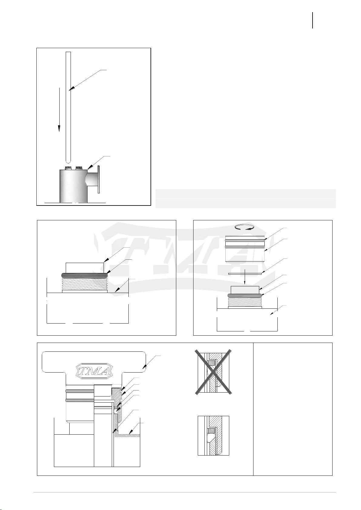
5.2. QUARTZ SLEEVES ASSEMBLY
(GRAFICAL MOUNTING INSTRUCTION ON PAGE 27-29)
a) Slide in gently through the nipple the quartz
sleeves; continue through sleeve guides onto
nests at the bottom.
b) Place the O-ring over quartz sleeve and against
the lip of the nipple. Next place the washer over
the O-ring, screw the muff onto this assembly
with the provided tool. Turn the muff to
considerable resistance in order to tighten the
seal. Tightening the muff shall not break the
sleeve.
c) Fill the chamber under full pressure and check
the seal tightness.
!!! ATTENTION !!!
Tightening the muffs with other tools may cause
quartz sleeves breakage.
O-RING
STERILIZER CHAMBER
QUARTZ SLEEVE
WASHER
O-RING
STERILIZER CHAMBER
QUARTZ SLEEVE
MUFF
O-RING ON MUFF
O-RING AFTER FULLY TIGHTENED,
MUFF DEFORMS O-RING
/SUFFICIENT DEFORMATION/
O-RING BEFORE MUFF TIGHTENED
/SMALL DEFORMATION OF O-RING/
WASHER
O-RING
STERILIZER CHAMBER
QUARTZ SLEEVE
MUFF
O-RING ON MUFF
PROVIDET TOOL
Tightest seal around
quartz sleeve shall be
created with the
largest possible
deformation of O-ring.
O-ring is visible
through the sleeve.
Tighten muff with the
provided tool, as seen.
STERILIZER CHAMBER
QUARTZ SLEEVE
WARNING!!
QUARTZ SLEEVE IS WERY
BRITTLE AND FRAGILE.
BE CAREFUL.

TMA
MANUAL –AP-POOL-X SERIES
14
TMA | Białostoczek 26,gm.Zabłudów,15-592 Białystok; Poland ; Tel. +48 857431246; VAT EU PL5420008413
5.3. UV LAMPS AND ELECTRICAL ENCLOSURE ASSEMBLY
(GRAPHICAL INSTRUCTIONS AT PAGE 27-29)
a) Mount electrical enclosure on wall, at least 60 cm from the floor.
b) Place the socket on the end of UV lamp with four pins. Gently slide the fully connected
lamp into the quartz sleeve.
!!! CAUTION !!!
MOUNT UV LAMPS IN PROTECTIVE, PREFERABLY COTTON GLOVES.
If not done as required, the UV lamps may break after turning on the device.
LAMP HOOD
STRAIN RELIEF
PLACE SOCKET ON
LAMP END WITH FOUR
PINS
UV LAMP
SOCKET
CENTERING RING
UV LAMP
STRAIN RELIEF
INSERT UV LAMP
INTO QUARTZ
SLEEVE
SOCKET
LAMP HOOD
PLACE LAMP HOOD
OVER MUFF
WASHER
O-RING
STERILIZER
CHAMBER
QUARTZ SLEEVE
MUFF
O-RING ON MUFF
CENTERING RING
c) Place lamp hood over muff.
d) Plug in to mains 230V, 50 Hz, in the electrical enclosure, according to the labels.
e) Turn device on by using switch on the side or front of electrical enclosure. Green
indicator light goes on when device is connected to power and powered up.
f) Replace UV lamps after its end of life time.
TMA
MANUAL –AP-POOL-X SERIES
15
TMA | Białostoczek 26,gm.Zabłudów,15-592 Białystok; Poland ; Tel. +48 857431246; VAT EU PL5420008413
ATTENTION!
1. Any fault of UV lamp, including burn out, is signalized by lighting up of red indicator lamp
and tripping of audible alarm.
2. Incidental powering of the electrical enclosure without connected UV lamps may cause
damage to electronic ballast driving UV lamps.
ATTENTION!
In case of installing solenoid shut-off valve ( terminals 1 & 2) upstream /or
downstream/ of the sterilizer, tripping alarm or power interruption causes immediate shutting
off of fluid flow to the chamber of the sterilizer / Section 4.3-4.6/. Terminals 1 & 2 are neutral.
Power to solenoid shut-off valve shall be connected through terminals 1 & 2.
Solenoid shut-off valve serves the purpose of preventing unsterilized fluid entering the
installation downstream of the sterilizer in the case of power interruption or lamp failure.
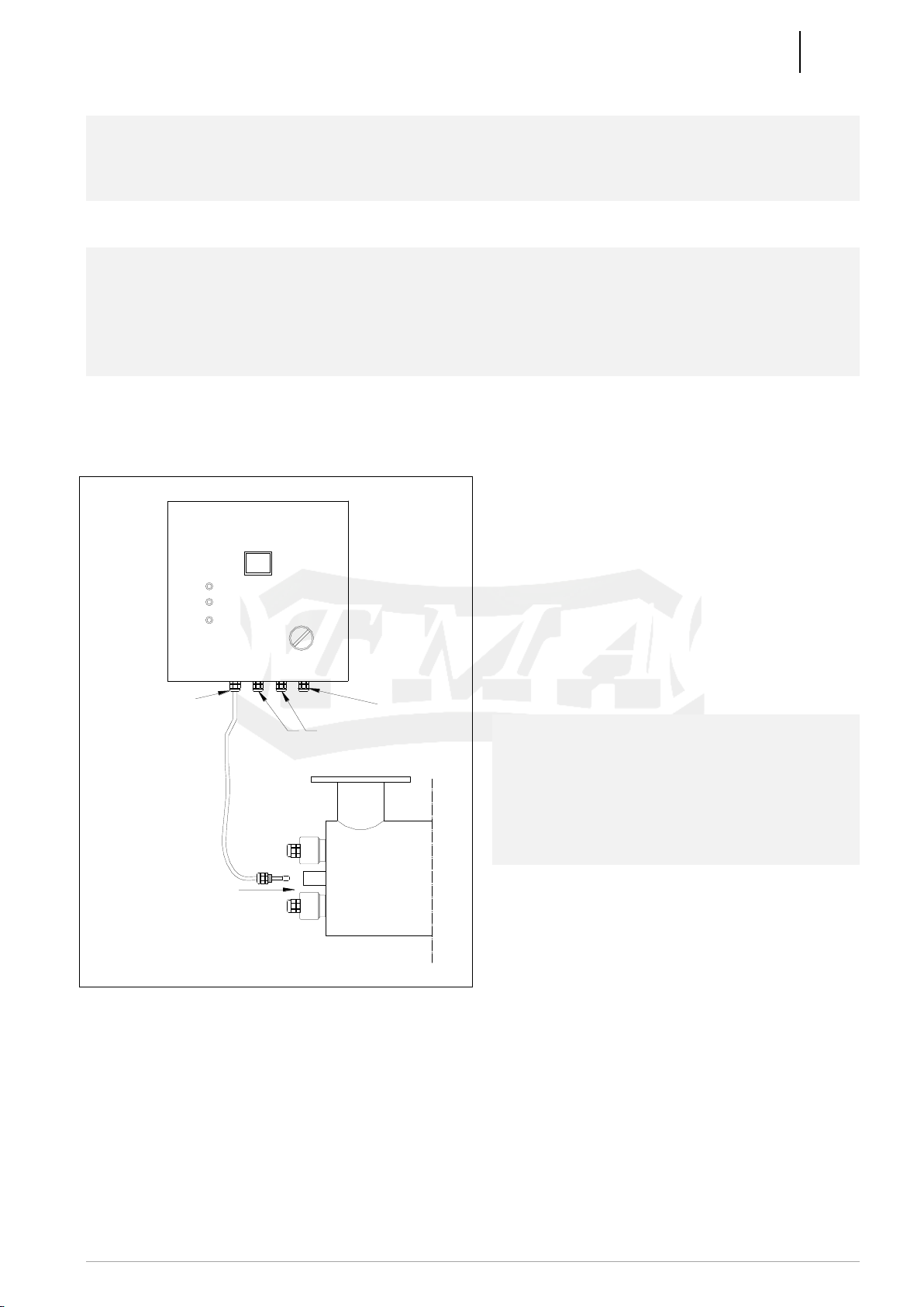
5.4. MOUNTING TEMPERATURE SENSOR (MODELS AP-POOL-X2-AP-POOL-
X16)
UV STERILIZER
POWER LINE
UV LAMPS
SCREW PLASTIC
GLAND INTO THE
STERILIZER
TEMPERATURE
SENSOR
ELECTRICAL ENCLOSURE
a) Choose the temperature sensor cord
(ended with strain relief PG11).
b) Loosen the cable gland
c) Install the strain relief into the hole at
the center of sterilizer (between the UV
lamps mountings)
d) Move the wire to the end of the hole.
e) Tighten the strain relief.
ATTENTION!
Improper mounting of temperature sensor
can cause a short circuit, resulting in failure
of whole device
Turning off radiators occurs at a
temperature of approx. 85°C. Resuming at
approx. 65°C

TMA
MANUAL –AP-POOL-X SERIES
16
TMA | Białostoczek 26,gm.Zabłudów,15-592 Białystok; Poland ; Tel. +48 857431246; VAT EU PL5420008413
6. DESCRIPTION OF ALARMS IN ELECTRICAL CABINET / AP-POOL-X1 /
Display indications
Cause
Solving the problem
- Blinking digit 7 on the display.
- An intermittent sound signal
- 7 days left to the end of life
time of UV lamp
- change UV lamp after 7
days.
HOLD 3 s.
PRZYTRZYMAĆ 3 s.
Hold left button more than 3
seconds to silence the sound alarm
- Blinking number 0 on the display.
- An intermittent sound signal
- UV lamp reached its end of
life time.
HOLD 3 s.
PRZYTRZYMAĆ 3 s.
Hold left button more than 3
seconds to silence the sound alarm
(max 2 times)
- Blinking number 0 on the display.
- Blinking 3 LED’s over display
- Continuous sound signal
- UV lamp is damaged or
reached its end of life time.
Change UV lamp
- The display shows weird characters.
- Two or three LEDs appear on the display
at the same time
- Possible damage to the
display or the
microprocessor.
Please Contact your dealer
- No indication on the display
- No indication on LED above display
- No audible alarm
- No power at the input of the
control cabinet.
- Check power supply.
- Check the fuse in the
alarm system

TMA
MANUAL –AP-POOL-X SERIES
17
TMA | Białostoczek 26,gm.Zabłudów,15-592 Białystok; Poland ; Tel. +48 857431246; VAT EU PL5420008413
7. RESSETING COUNTER IN ALARM SYSTEM / ONLY MODEL AP-POOL-X1/
COUNTER IN THE ALARM SYSTEM SHOULD BE RESSETED EACH TIME THE UV
LAMP IS REPLACED
a) Disconnect from power supply /neutral and life/.
b) Replace UV Lamp –see p. 9. INSTRUCTION FOR REPLACEMENT OF UV LAMP
c) Connect device to Power supply (power switch should be turned off)
d) Hold the right button under display.
01
NACISNĄĆ I PRZYTRZYMAĆ OK
CZEKAJ 10 SEKUND
e) Turn on the power switch while still holding the right button for more than 10 seconds.
f) Short sound signal will confirm resetting the work time counter.
8. LEGEND FOR INDICATOR LIGHT ON ENCLOSURE
Lighted color indicator lights inform the operator of the status of the sterilizer. Certain
conditions can be identified from the configuration of lights. For these corrective actions are
listed below:
Alarm
Red Light
Power Supply
Green Light
Power
Green Light
Problem
Action
OFF
ON
ON
No fault
-
OFF
BLINKING
ON
No fault –heating the
UV lamps
-
OFF
OFF
OFF
No Power
Check power
source
ON
OFF
ON
1.Burned out or faulty
UV lamp
2.Faulty starter
1.Replace UV
lamp
2.Replace starter
OFF
OFF
ON
Alarm System Fault
Contact Dealer.
Replace alarm
system.

TMA
MANUAL –AP-POOL-X SERIES
18
TMA | Białostoczek 26,gm.Zabłudów,15-592 Białystok; Poland ; Tel. +48 857431246; VAT EU PL5420008413
9. MAINTENANCE
a) UV radiation is harmful to eyes and skin. It is forbidden to directly observe UV
lamp (radiator) during operation.
b) It is recommended to check cleanness of the quartz sleeve whenever the UV lamp is
replaced.
c) If any sediment is noticed on the surface of the quartz sleeve, it is recommended to
immediately clean the sleeve. Negligence of this recommendation can cause drop in
efficiency of sterilization.
d) Any time the sleeve is cleaned or replaced it is required to
unconditionally replace the O-ring creating the seal around the sleeve.
e) Inlet and outlet valves shall be opened slowly to prevent the rush of fluid hitting and
damaging the quartz sleeve.
f) There is no need for minimal flow through the device as it is designed in such a way
that there may be no flow through the chamber with no damage to the sterilizer. When
there is no flow of water through the chamber can heat up to approx. 85°C that is
when turning off radiators occurs. Sterilizer is resumed to work after reaching
temperature of approx. 65°C.
g) UV sterilizer should work constantly - his long-term exclusion may cause secondary
infection in the installation, which is very difficult to remove.
h) It is recommended that before the UV sterilizer a filter is installed.
i) Water not fit for consumption may require treatment i.e. deironing, softening or
filtering. If any doubt, please contact your dealer.
j) In case of high turbidity and waste water, the choice of equipment and efficiency
should be made by the dealer.
k) Sterilizers must be sized for the maximum momentary flow of water (matching them to
the daily flows may result in incomplete disinfection)
l) Avoid frequent turning on and off the equipment. One on-off cycle lowers the UV lamp
life by about 10-20 hours.
m) Sterilizers should not be installed in such a way that their work was dependent on
other devices, e.g. pumps, pressure-water.
n) Flow rate through the device can be increased; however, this lowers the delivered
dosage and lowers the efficiency of disinfection.
o) The lamp needs about 2 minutes to reach full capacity at temperature of water about
12-16 °C. If the water is at temperature 5-12°C, the time might be about 3-5 minutes.
p) If the sterilizer is left idle for longer period of time or it can freeze, we recommend that
the water be drained from the chamber. The chamber is provided with drain valve.
q) Bioassay samples shall be collected into sterile opaque containers as not to
expose the sample to the light to avoid photo reactivation of microorganisms,
which can rebuild their damaged DNA in presence of light.
r) In case the red indicator light is on, replacement of the UV lamp is necessary. The
part number can be found on transparent plastic lamp hood placed over the muff.
s) Even short lived surge, to above 254V, can damage the electronic ballast driving the
UV lamps.

TMA
MANUAL –AP-POOL-X SERIES
19
TMA | Białostoczek 26,gm.Zabłudów,15-592 Białystok; Poland ; Tel. +48 857431246; VAT EU PL5420008413
t) Using faulty or post end of life UV lamps / operating time above their durability period /
can lead to damage to electronic ballast located in the electrical enclosure. When
replacing the UV lamp, protective gloves should be worn.
u) Excessive humidity and water inside the quartz sleeve can cause damage to the
power supply of the UV lamp.
v) The leakage current going into grounding is 1,5 mA for each UV lamp.
w) Fans in control cabinets should be replaced every 50 000h.
x) In control cabinets there are mounted protection devices as below:
Sterilizer type
Protection device
AP-POOL-X1
Fuse 2A
AP-POOL-X2
Circuit breaker C6
AP-POOL-X3
Circuit breaker C6
AP-POOL-X4
Circuit breaker C10
AP-POOL-X5
Circuit breaker C10
AP-POOL-X6
Circuit breaker C13
AP-POOL-X8
Circuit breaker C16
AP-POOL-X10
Circuit breaker C20
AP-POOL-X12
Circuit breaker C16
AP-POOL-X16
Circuit breaker C16
10. INSTRUCTION FOR REPLACEMENT OF UV LAMP
(GRAPHICAL INSTRUCTIONS AT PAGE 28-29)
ATTENTION!
1. Always wear protective gloves (preferably cotton) when replacing / installing the UV lamp.
Do not touch the UV lamp with your bare hand.
2. When installing the UV lamp, hold the lamp by the glass.
3. Holding or inserting the UV lamp by the lampholder may damage it.
In order to replace the UV lamp one shall:
a) Disconnect from power supply /neutral and life/,
Replacing the radiator does not require shutting off the water flow through the chamber.
b) Put on protective gloves, preferably made of cotton,
c) Take off plastic hood,
d) Slide out the UV lamp from the quartz sleeve,
DO NOT UNSREW THE STEEL MUFF!
e) Remove sockets from connectors of the UV Lamp,
f) Remove old UV lamp from the quartz sleeve,
g) Carefully place the new UV lamp in the sleeve,
h) Reverse the remaining steps.

TMA
MANUAL –AP-POOL-X SERIES
20
TMA | Białostoczek 26,gm.Zabłudów,15-592 Białystok; Poland ; Tel. +48 857431246; VAT EU PL5420008413
ATTENTION!
In model AP-POOL-X sterilizers UV lamps must have special centering ring at both ends.
When the UV lamps are shipped from the manufacturer, the centering rings are provided with
every lamp.
11. REPLACEMENT AND CLEARING OF THE QUARTZ SLEEVE
(WARNING: VERY BRITTLE)
(GRAPHICAL INSTRUCTIONS AT PAGE 28)
In order to replace quartz sleeve one shall:
a) Disconnect the power supply,
b) Cut off the liquid flow through the chamber,
c) Allow for lamp to cool down from operating temperature,
d) Remove UV lamp according to p. 10. /Instruction for replacement of UV lamp/,
e) Unscrew the steel muff using special spanner,
f) Take off the washer and O-ring from the quartz sleeve,
g) Slide the sleeve out of guides and nipple of the sterilizer,
h) Every time the UV lamp is replaced, when it is necessary to clean the quartz sleeve
use common glass cleaners and then inside of the sleeve should be thoroughly dried
so that no liquid is left there,
ATTENTION! SLEEVE IS MADE OF PURE QUARTZ –VERY BRITTLE
ATTENTION!
AT THE TIME OF REPLACEMENT OR CLEARING OF THE QUARTZ SLEEVE, THE O-RING MUST BE REPLACED
i) Slide carefully the new or cleaned quartz sleeve into the chamber of the sterilizer,
j) Place new O-ring over the sleeve, then place the washer,
k) Tighten the muff over the O-ring and washer with the provided tool. Check the proper placement of the
O-ring, it should be lodged into the conical groove in the nipple of the sterilizer,
l) Open gradually the cut-off valves, flood the chamber, and check the seal around the
sleeve. If it springs a leak, tighten the muff till tight seal is obtained,
m) Place the UV lamp according with p. 10 of this Manual.
This manual suits for next models
11
Table of contents
Other TMA Laboratory Equipment manuals


Popular Laboratory Equipment manuals by other brands

Shimadzu
Shimadzu GC quick start guide

Labnet
Labnet 35 operating instructions

Sartorius
Sartorius Sartocheck 4 plus operating instructions

Thermo Scientific
Thermo Scientific Cryofuge 5500i GMP Instructions for use

Atop
Atop IJG7001 Series Hardware installation guide

Yamato
Yamato NeoCool Circulator CF301 instruction manual


Izon
Izon AUTOMATIC FRACTION COLLECTOR V2 quick start guide

S.C.A.T. Europe
S.C.A.T. Europe SymLine asecos Assembling and installation manual

Westlab
Westlab 665-090 product manual

AGS
AGS Merlin 1000S Installation & operation manual

Covaris
Covaris E220 evolution user manual

Agilent Technologies
Agilent Technologies 1260 Infinity II user manual