TMA V Series User manual

®
Manufactured in Poland
WATER STERILIZERS
V SERIES
MODELS: V9;V12; V20; V20LA; V25; V25LA;
V35; V40; V80; V120
MANUAL
Patent no. 204935
Version - November 2018
WATER AND AIR UV STERILIZERS

TMA
V9 –V120
2
TMA | Białostoczek 26,gm.Zabłudów,15-592 Białystok; Poland ; VAT PL5420008413; GIOŚ: E0021166WZ;
Tel. +48 857431246
TABLE OF CONTENTS:
1. GENERAL INFORMATION ...........................................................................................................4
2. APPLICATIONS.............................................................................................................................5
3. TECHNICAL DESCRIPTION ..........................................................................................................5
4. TECHNICAL SPECIFICATION.......................................................................................................6
5. INSTRUCTIONS FOR INSTALLATION AND OPERATION .............................................................8
5.1. CORRECT ASSEMBLY OF THE CHAMBER ............................................................................8
5.2. CORRECT ASSEMBLY OF THE ELECTRICAL ENCLOSURE ...................................................9
6. CONNECTION OF SOLENOID VALVE OR LEADING THE ALARM SIGNAL OUT IN V20LA,
V25LA, V40, V80, V120.............................................................................................................10
6.1. CONNECTION OF SOLENOID VALVE ...............................................................................11
6.2. LEADING OUT THE ALARM SIGNAL ...................................................................................11
6.3. REMOTE-CONTROLLED ON/OFF SWITCH (IN V20LA-V120)............................................11
7. MAINTENANCE..........................................................................................................................11
8. DESCRIPTION OF INDICATORS IN ELECTRICAL ENCLOSURES...............................................12
8.1. IN V9, V12, V20, V25, V35 ..................................................................................................12
8.2. IN V20LA, V25LA, V40, V80, V120 .....................................................................................13
9. V SERIES STERILIZERS SERVICE...................................................................................................14
9.1. REPLACEMENT OF UV LAMP .............................................................................................14
9.2. RESETTING THE COUNTER IN THE ALARM SYSTEM /IN V20LA, V25LA, V40, V80, V120/ 14
9.3. REPLACEMENT AND CLEANING OF THE QUARTZ SLEEVE /FRAGILE AND BRITTLE/.......15
9.4. TROUBLESHOOTING...........................................................................................................15
10. SPARE PARTS LIST.......................................................................................................................16
11. GRAPHIC ASSEMBLY INSTRUCTIONS .......................................................................................17
11.1. ASSEMBLY OF THE STERILIZERS WITH BRACKETS –V20,V20LA,V35,V40, V80, V120 .......17
11.2. ASSEMBLY OF THE ELECTRICAL ENCLOSURES IN V20LA, V25LA, V40, V80, V120 ........18
11.3. ASSEMBLY OF V9, V12, V25, V25LA ..................................................................................19
11.4. ASSEMBLY OF V20, V20LA, V35, V40, V80........................................................................20
11.5. ASSEMBLY OF V120 ............................................................................................................21
12. DECLARATION OF CONFORMITY............................................................................................22
13. HYGIENIC CERTIFICATE ............................................................................................................23
14. SHIPPING....................................................................................................................................24
15. WARRANTY ................................................................................................................................24

TMA
V9 –V120
3
TMA | Białostoczek 26,gm.Zabłudów,15-592 Białystok; Poland ; VAT PL5420008413; GIOŚ: E0021166WZ;
Tel. +48 857431246
USER SAFETY
WARNING!!!
This device may only be operated and installed by qualified
personnel. Before installation, servicing or repairs verify the qualifications
and limit these activities to such personnel. Any activities on this device
can only proceed after thorough familiarization with this instruction.
Noncompliance with the precautions listed hereon might expose the
personnel to serious bodily harm (damage to human skin from UV
radiation), or damage to the device alone. The manufacturer, TMA, is not
responsible for damage to the device caused by improper installation,
maintenance and operation.
READ THE MANUAL
Before proceeding with any activity with the sterilizers read the manual.
Familiarize the personnel with the manual and safety instructions. Retain the manual for
reference during the whole time the device is in operation. All precautions and warnings shall
be obeyed by the user at all times during the operation of the device.
UV RADIATION
TMA UV Sterilizers use lamps that emit UVC radiation. The design of the sterilizers ensures the
safety of the user. Direct exposure to UV radiation is harmful to human skin and sight. As a result
of direct UV radiation, reddening of skin, serious burns or ultimately loss of eyesight may occur
(depending on the time of exposure). In such cases one shall contact a physician as soon as
possible. Direct exposure to UVC radiation should be strictly avoided. UVC radiation used for
disinfection cannot be used for medicinal or cosmetic purposes.
POWER SUPPLY
The device is exclusively designed to be supplied from 220-230V 50Hz mains. It shall be installed
and grounded in accordance with this manual and the local electrical code.
To guard against electrical shock, unplug the device every time work is to be done on it.
GROUNDING
Operation of the device without connected grounding is inadmissible!
Ungrounded operation might lead to occurrence of electrical shock and serious bodily harm
with death included.
OPERATION SAFETY/SERVICE
The use of original parts provided by TMA ensures appropriate safety and UV disinfection
efficacy conditions. All maintenance activities on this device can only be performed by
qualified personnel. Noncompliance with the safety precautions as well as inadequate use of
the device may result in body and eyesight damage.

TMA
V9 –V120
4
TMA | Białostoczek 26,gm.Zabłudów,15-592 Białystok; Poland ; VAT PL5420008413; GIOŚ: E0021166WZ;
Tel. +48 857431246
1. General information
Thank you for your purchase of TMA manufactured UV sterilization product. All the raw
materials and components are of best quality and were processed or manufactured in the EU
countries. Sterilizers made by TMA are made from highest quality stainless steel. The thickness of the
chamber wall guarantees high factor of safety in operation. All of the devices successfully
completed 30 Atm pressure trials.
The innovative design of the TMA sterilizers allows for continuous work of the devices even
without the flow of water through the chamber. The design of the chamber contributes to lower
incidence of sediment from calcium and magnesium on the surface of the quartz sleeve.
In the sterilizers of the V series we introduced additional guides for the quartz sleeves easing
the assembly and disassembly. The solution allows for the same ease of assembly for device working
horizontally, vertically or at any other angle. The guide prevents the quartz sleeve from breaking
during routine maintenance. The turbulent flow induced by the guide increases the efficiency of
disinfection. During the first 100 hours of operation the efficiency of disinfection is greater by 15%
from the rated for the device.
We provide you with devices equipped with a new electronic control panel (in V20LA,
V25LA, V40, V80, V120) that indicates:
Total work time (days),
Remaining time until UV lamp replacement (days),
Number of ON/OFF cycles,
Visual and audible signal 7 days before the required UV lamp replacement,
Visual and audible signal when UV lamp replacement is required,
Visual and audible signal when UV lamp is burnt out.
The detailed instructions of the new panel are provided on the casing of the electrical
enclosure.
Sterilizers of the V series have a steel muff with a hood that functions as a sight glass. This
innovative solution of a light muff allows for optical control of the working condition of the lamp.
We hold high hopes that the implementations of these innovative solutions in the V series
sterilizers fulfill your expectations concerning the effectiveness and operation of our devices.
The device delivered to you shall be protected from severe shocks and drops, as the quartz
sleeve and UV lamps are brittle and fragile. The sterilizer shall be transported exclusively in horizontal
position. The manufacturer is not responsible for damage arising from the conditions of transport.
Before installation and operation one shall read the instructions and implement the
precautions listed. Noncompliance with these precautions is grounds for releasing the manufacturer
from warranty obligations.
The used electrical and electronic equipment with the crossed-out rubbish bin symbol shall be collected
separately. It is prohibited to put the used equipment with other waste. Inadequate use of the used
equipment may have a negative impact on the environment and people's health. Separate collection
of the equipment contributes to its re-use and recycling. The obligation of the used equipment selective
collection rests on the user, who should provide it to the used equipment collector.
TMA devices are equipped with lamps that emit UV radiation, light sources that contain mercury. The
owners of waste lamps containing mercury are obliged to collect them separately for further re-use and
disposal.

TMA
V9 –V120
5
TMA | Białostoczek 26,gm.Zabłudów,15-592 Białystok; Poland ; VAT PL5420008413; GIOŚ: E0021166WZ;
Tel. +48 857431246
2. Applications
Disinfection with UV radiation is a reliable, simple and inexpensive method of sterilization.
The use of this method is possible whenever microbiological risk exists.
The applications of this method are, among many others:
Potable water in private and municipal installations
Potable and process water in restaurant and hotel business
Process water in the production of medicines and cosmetics
Water used in processing food
Water in beverage production
Water in swimming pools and fountains
Control of green algae and bacterias in ponds
And many more
The sterilizer uses special low pressure UV lamp that produces UV radiation of wavelength of
254 nm, which causes photochemical reaction damaging DNA of microorganisms and their
disintegration.
Water flowing from the sterilizer is ready for immediate use. UV sterilization does not change the
chemical makeup of water.
THERE IS NO POSSIBILITY OF OVERDOSING UV RADIATION
DURING WATER STERILIZATION IN THE CHAMBER.
MINIMAL FLOW OF WATER IS NOT REQUIRED.
INCREASED FLOW THROUGH THE STERILIZER LOWERS THE DOSAGE DELIVERED TO
MICROORGANISMS AND LOWERS EFFICIENCY OF DISINFECTION.
3. Technical description
Sterilizer’s chamber is made from stainless steel AISI 304 or AISI 316.
Power supply is 220-240V + 8%, - 10%, 50-60 Hz.
Electric shock protection by earth terminal.
Power optical indicator in the electrical enclosure enables the indication of the working
condition of the lamp.
Sight glass muff enables the indication of the working condition of the UV lamp.
Models V9,V12,V20,V25,V35 are equipped with a simple power supply.
Models V20LA,V25LA,V40,V80,V120 are equipped with an alarm system with a digital display
that shows the remaining work time of the UV lamp, total work time of the device and the
number of on/off switch cycles. In these models there is a possibility of connecting a solenoid
valve or leading the alarm signal out.
No. HK/W/0521/01/2015
Valid until: 2020-07-16

TMA
V9 –V120
6
TMA | Białostoczek 26,gm.Zabłudów,15-592 Białystok; Poland ; VAT PL5420008413; GIOŚ: E0021166WZ;
Tel. +48 857431246
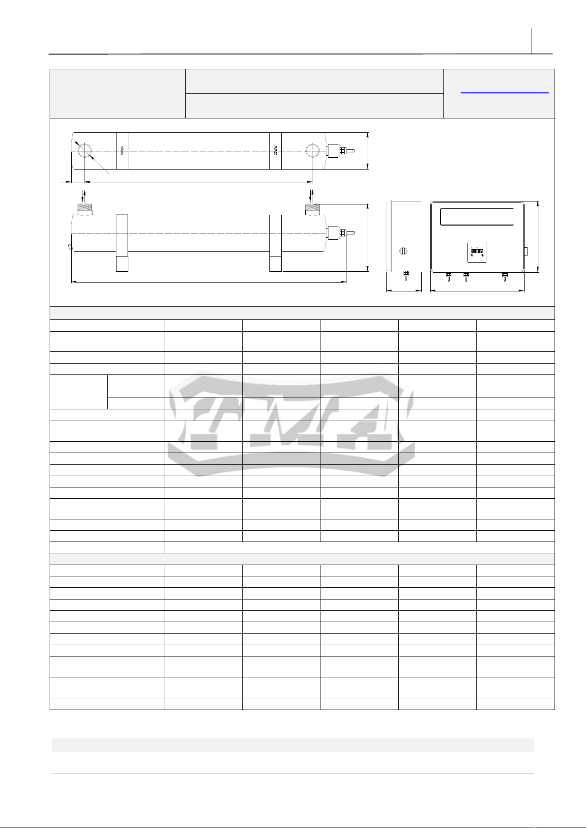
4. Technical specification
TMA
Białostoczek 26;
gm. Zabłudów,
15-592 Białystok
WATER STERILIZERS- V series
Tel. 85 743 12 46; 85 687 14 50
www.tma.pl,www.tma.com.pl;
e-mail:biuro@tma.pl
NIP: 542-000-84-13
Models: V9; V12; V20; V20LA; V25
POWER CORDUV LAMP CABLE
ELECTRICAL ENCLOSURE
www.tma.pl biuro@tma.pl +48 85 743 12 46
®
WYPRODUKOWANE W POLSCE / MADE IN POLAND
ZASILACZ DO STERYLIZATORA UV
POWER SUPPLY FOR UV STERILIZER V6 - V40
Un [ V ] In [ A ] fn [ Hz ] ?Uo ut [ V ]
~220...240 AC 0,10...0,18A 50...60 ?0.96 <330
TMA / BIAŁOSTOCZEK 26, GM. ZABŁUDÓW / 15-592 BIAŁYSTOK / POLSKA
ODŁĄCZYĆ ZASILANIE PRZED INSTALOWANIEM LUB WYMIANĄ ELEMENTÓW
/DISC ONNECT LINE VOLTAGE BEFORE INSTALLINGOR REPLACING PARTS
PRZED INSTALACJĄ PRZECZYTAĆ INSTRUKCJĘ/ R EAD MANUALBEFORE
INSTALLATION
PRZEZNACZONE TYLKO DO PRACY ZE STERYLIZATORAMIFIRMY TMA /
SUITABLE ONLY FOR TMA UV STERILIZERS
ZAWIERA CZĘŚCI NIE PODLEGAJĄCE SERWISOWANIU / NON SERVICEABLE
PARTS INSIDE
UWAGA ! CAUTION !
WYSOKIE NAPIĘCIE, ZAGROŻENIE PORAŻENIA
PRĄDEM ELEKTRYCZNYM - NIE OTWIERAĆ ! /
HIGHV OLTAGE ELECTRICAL SHOCK
HAZARD- DO NOT OPEN !
TYLKO DO UŻYTKU WEWNĘTRZNEGO /
FORIN DOOR USE ONLY
OSTRZEŻENIE ! / DANGER !
PROMIENNIKI UV NALEZY WYMIENI AĆ PO UPŁYWIE OKRESU ICH ŻYWOTNOŚCI (PATRZ INSTRUKCJA) /
UVLAMPS SHOULD BE REPLAC ED AFTER THEIR ENDOF LIFE TIME (SEE MANUAL)
a
b c
LZ
DN
INLET / OUTLET
DY
INLET / OUTLET
X
L1
TECHNICAL SPECIFICATIONS:
Model
V9
V12
V20
V20LA
V25
Power Supply
~220V-240V 50-
60Hz
~220V-240V 50-
60Hz
~220V-240V 50-
60Hz
~220V-240V 50-
60Hz
~220V-240V 50-
60Hz
Material
Stainless Steel
Stainless Steel
Stainless Steel
Stainless Steel
Stainless Steel
Finish
Satin (Ra<0,8µm)
Satin (Ra<0,8µm)
Satin (Ra<0,8µm)
Satin (Ra<0,8µm)
Satin (Ra<0,8µm)
Dimensions
X / Y / Z
395x94x70mm
640x100x70mm
660x130x240mm
660x130x240mm
960x100x70mm
L
274mm
518mm
495mm
495mm
815mm
DN / D
DN15 (R ½”)
DN20 (R 3/4”)
DN25 (R 1”)
DN25 (R 1”)
DN25 (R 1”)
Safety Class
IP66
IP66
IP66
IP66
IP66
No. of UV Lamps x Nominal
Power
1x 15W
low pressure
1x 24W
low pressure
1x 24W
low pressure
1x 24W
low pressure
1x 40W
low pressure
Life of UV Lamps
About 9 000 h
About 9 000 h
About 9 000 h
About 9 000 h
About 9 000 h
Operating Temperature
0,5-45 0C
0,5-45 0C
0,5-45 0C
0,5-45 0C
0,5-45 0C
Operating Pressure
10bar(1MPa)
10bar(1MPa)
10bar(1MPa)
10bar(1MPa)
10bar(1MPa)
UV Power at 254nm
4,0 W
7,8W
7,8W
7,8W
15,0W
Nominal Power
16W
25W
25W
25W
41W
Nominal Flow at transmittance
T10=95%,dose 400J/m2
0.50m3/h
1.00m3/h
2.00m3/h
2.00m3/h
2.00m3/h
Optical Power Indicator
Yes
Yes
Yes
Yes
Yes
Drain Valve
No
No
Yes
Yes
Yes
Orientation
From horizontal to vertical
ELECTRICAL ENCLOSURE
Material
Aluminum/ABS
Aluminum/ABS
Aluminum/ABS
Plastic ABS
Aluminum/ABS
Safety Class
IP 41
IP 41
IP 41
IP65
IP 41
Dimensions
390x83x70mm
390x83x70mm
390x83x70mm
325x250x120mm
390x83x70mm
Audible UV Lamp Fault Alarm
No
No
No
No
No
Optical UV Lamp Fault Indicator
Yes
Yes
Yes
Yes
Yes
Optical Power Indicator
Yes
Yes
Yes
Yes
Yes
Total work time counter
No
No
No
Yes
No
Solenoid Valve Terminals
No
No
No
Yes
No
Terminals for Remote Alarm
Indicator
No
No
No
Yes
No
UV Intensity Measurement
System
On demand/
Additional charge
On demand/
Additional charge
On demand/
Additional charge
On demand/
Additional charge
On demand/
Additional charge
Weight with Enclosure
2.7kg
3.6kg
6.2kg
7.4kg
4.7kg
TMA
V9 –V120
7
TMA | Białostoczek 26,gm.Zabłudów,15-592 Białystok; Poland ; VAT PL5420008413; GIOŚ: E0021166WZ;
Tel. +48 857431246
TMA Company reserves the right to make design changes without notice.
TMA
Białostoczek 26;
gm. Zabłudów,
15-592 Białystok
WATER STERILIZERS-V series
Tel. 85 743 12 46; 85 687 14 50
www.tma.pl,www.tma.com.pl;
e-mail:biuro@tma.pl
NIP: 542-000-84-13
Models: V25LA; V35; V40; V80; V120
L
Z
DN
b
ac
NALEPKA
L1
XY
INLET/OUTLET ELECTRICAL ENCLOSURE
INLET/OUTLET
TECHNICAL SPECIFICATIONS:
Model
V25LA
V35
V40
V80
V120
Power Supply
~220V-240V 50-
60Hz
~220V-240V 50-
60Hz
~220V-240V 50-
60Hz
~220V-240V 50-
60Hz
~220V-240V 50-
60Hz
Material
Stainless Steel
Stainless Steel
Stainless Steel
Stainless Steel
Stainless Steel
Finish
Satin (Ra<0,8µm)
Satin (Ra<0,8µm)
Satin (Ra<0,8µm)
Satin (Ra<0,8µm)
Satin (Ra<0,8µm)
Dimensions
X / Y / Z
960x100x70mm
960x130x240mm
960x130x240mm
960x130x240mm
960x130x240mm
L
815mm
880mm
880mm
880mm
880mm
DN / D
DN25 (R 1”)
DN40(R1 1/2”)
DN40 (R 1 1/2”)
DN40 (R 1 1/2”)
DN50 (R 2”)
Safety Class
IP66
IP66
IP66
IP66
IP66
No. of UV Lamps x Nominal
Power
1x 40W
low pressure
1x 40W
low pressure
1x 40W
low pressure
1x 75W
low pressure
1x 130W
low pressure
Life of UV Lamps
About 9 000 h
About 9 000 h
About 9 000 h
About 9 000 h
About 9 000 h
Operating Temperature
0,5-45 0C
0,5-45 0C
0,5-45 0C
0,5-45 0C
0,5-50 0C
Operating Pressure
10bar(1MPa)
10bar(1MPa)
10bar(1MPa)
10bar(1MPa)
10bar(1MPa)
UV Power at 254nm
15,0W
15,0W
15,0W
25,0W
46,0W
Nominal Power
41W
41W
41W
80W
160W
Nominal Flow at transmittance
T10=95%,dose 400J/m2
2.00m3/h
3.60m3/h
3.60m3/h
5.90m3/h
11.00m3/h
Optical Power Indicator
Yes
Yes
Yes
Yes
Yes
Draining System
No
Yes
Yes
Yes
Yes
Orientation
From horizontal to vertical
ELECTRICAL ENCLOSURE:
Material
Plastic ABS
Aluminum/ABS
Plastic ABS
Plastic ABS
Plastic ABS
Safety Class
IP65
IP 41
IP65
IP65
IP65
Dimensions
325x250x120mm
390x83x70mm
325x250x120mm
325x250x120mm
325x250x120mm
Audible UV Lamp Fault Alarm
Yes
Yes
Yes
Yes
Yes
Optical UV Lamp Fault Indicator
Yes
Yes
Yes
Yes
Yes
Optical Power Indicator
Yes
Yes
Yes
Yes
Yes
Total work time counter
Yes
No
Yes
Yes
Yes
Solenoid Valve Terminals
Yes
No
Yes
Yes
Yes
Terminals for Remote Alarm
Indicator
Yes
No
Yes
Yes
Yes
UV Intensity Measurement
System
On demand/
Additional charge
On demand/
Additional charge
On demand/
Additional charge
On demand/
Additional charge
On demand/
Additional charge
Weight with Enclosure
5.9kg
8.6kg
9.8kg
10.2kg
11.5kg

TMA
V9 –V120
8
TMA | Białostoczek 26,gm.Zabłudów,15-592 Białystok; Poland ; VAT PL5420008413; GIOŚ: E0021166WZ;
Tel. +48 857431246
ATTENTION!
Minimal flow of water is not required for the devices to work.
Increased flow through the sterilizer lowers the efficiency of disinfection.
The device is comprised of stainless steel chamber and electrical enclosure.
5. Instructions for installation and operation
5.1. CORRECT ASSEMBLY OF THE CHAMBER
(graphic instructions at the end of the Manual)
INLET OUTLET
INLET
OUTLET
Vertical
INLET OUTLET
INLET
OUTLET
Diagonal
INLET/OUTLET INLET/OUTLET
INLET/OUTLET INLET/OUTLET
Horizontal
ATTENTION!!!
The sterilizer shall be mounted in a way that prevents the creation of air pockets in the chamber:
connectors shall be placed upwards in the horizontal position, water inlet on the bottom in the
vertical and diagonal position. The UV lamp shall always be mounted in a horizontal or upward
position.

TMA
V9 –V120
9
TMA | Białostoczek 26,gm.Zabłudów,15-592 Białystok; Poland ; VAT PL5420008413; GIOŚ: E0021166WZ;
Tel. +48 857431246
FILTER min.
0,1 mm
INLET
CONTAMINATED
WATER
POWER LINE
ELECTRICAL ENCLOSURE
OUTLET
DISINFECTED
WATER
WATER SAMPLE
TAKE-UP VALVE
DISTANCE EQUAL TO THE
LENGHT OF THE STERILISER
SHUT-OFF VALVES
HORIZONTAL MOUNTING ARRANGEMENT OF THE UV STERILISER
www.tm a.pl biuro @tma.pl +4 8 85 743 12 46
®
WYPRODUKOWANE W POLSCE /MADE INPOLAND
ZASILACZ DO STERYLIZATORA UV
POWER SUPPLY FOR UV STERILIZER V6 - V40
Un [ V ] In [ A ] fn [ Hz ] ?Uout [ V ]
~220...240AC 0,10...0,18A 50...60 ?0.96 <330
TMA / BIAŁOSTOCZEK 26, GM. ZABŁUD ÓW / 15-592 BIAŁYSTOK / POLSKA
ODŁĄCZYĆ ZASILANIE PRZED INST ALOWANIEM LUB WYMIANĄ ELEMENTÓW
/DISCO NNECT LINE VOLTAGE BEFORE INSTALLING OR REPLACINGPARTS
PRZED INSTALACJĄ PRZECZYTAĆ INSTRUKCJĘ / READ MANUAL BEFORE
INSTALLATION
PRZEZNACZONE TYLKO DO PRACY ZE STE RYLIZATORAMIFIRMY TMA/
SUITABLE ONLY FOR TMA UV STERILIZERS
ZAWIERA CZĘŚCI NIE PODLE GAJĄCE SERWISOWANIU / NON SERVICEABLE
PARTS INSIDE
UWAGA ! CAUTION !
WYSOKIE NAPIĘCIE, ZAGROŻENIE PORAŻENIA
PRĄDEM ELEKTRYCZNYM - NIE OTWIERAĆ ! /
HIGHVO LTAGE ELECTRICAL SHOCK
HAZARD- DO NO TOPEN !
TYLKO DO UŻYTKU WEWNĘTRZNEGO /
FORINDO OR USEONLY
OSTRZEŻENIE ! / DANGER !
PROMIENNIKI UV NALEZY WYMIENIAĆ PO UPŁYWIE OKRESU ICH ŻYWOTNOŚCI (PATRZ INSTRUKCJA) /
UVLAMPS SHOULD BE REPLACED A FTER THEIR END OF LIFE TIME (SEE MANUAL)
1) Temperature range for installation is from 5 to 45oC.
2) Upstream of the intake install potable water filter. Minimum rating 0.1 mm, recommended
0.05 mm. The use of mesh screen filters is recommended (string wound filters may cause the
multiplication of microorganisms).
3) Install manual cut-off valves, upstream of intake and downstream of outlet.
4) Close solenoid valves.
5) Connect the sterilizer chamber to water supply.
6) Mount the quartz sleeve into the chamber.
7) Place o-rings over the quartz sleeve. Next place the washer over the o-ring, screw the muff
onto this assembly. Turn the muff to considerable resistance in order to tighten the seal. Use
provided spanner to retighten the muff. Tightening the muff shall not break the sleeve. The
use of any sealing materials for screwing the muff is prohibited.
8) Slowly open the solenoid valves and check the seal.
9) After checking the seal, place the UV lamp in the sleeve.
10) Push the socket on the UV lamp and slide it inside the quartz sleeve.
11) Push lamp hood on the muff.
12) Check if the strain relief cap is properly screwed.
5.2. CORRECT ASSEMBLY OF THE ELECTRICAL ENCLOSURE
1) Mount the electrical enclosure on the wall, at least 120 cm from the floor.
2) The electrical enclosure in V20LA, V25LA, V40, V80, V120 shall be mounted with the provided
holders –check the graphic assembly instructions on p.18.
3) Plug the unit into grounded outlet 220-230V, 50-60 Hz.
4) Sight glass muff enables indication of working condition of the lamp.
5) Replace the lamp according to the indications for each model /see the table on p.6-7/.

TMA
V9 –V120
10
TMA | Białostoczek 26,gm.Zabłudów,15-592 Białystok; Poland ; VAT PL5420008413; GIOŚ: E0021166WZ;
Tel. +48 857431246
6. Connection of solenoid valve or leading the alarm signal out in
V20LA, V25LA, V40, V80, V120
BALAST ON/OFF SWITCH N L ~230V
1
1 221
ELECTRICAL ENCLOSURE
OUTLET
DISINFECTED WATER
WATER SAMPLE
TAKEUP VALVE
1.REMOVE DOORS
OF THE ELECTRICAL
ENCLOSURE
SOLENOID VALVE
UV STERILIZER
IN MODELS V20LA-V120
After removing the bridge, it is possible to
connect remote-controlled switch to the
terminals ON/OFF /caution: voltage 230V!/.
Contacts closed - sterilizer on
Contacts open- sterilizer off
IN MODELS V20LA-V120
It is possible to connect solenoid valve type NZ
(normally closed) max. 2a, or alarm signal to the
terminals 1 & 2 /neutral/ on the electronic plate in
electrical enclosure/.
Contacts closed - sterilizer working properly
Contacts open- UV lamp damage
- Alarm on
- Power cut off
POWERPOWER
2. TO THE TERMINALS 1 & 2 ON
ELECTRONIC PLATE CONNECT
SOLENOID VALVE OR ALARM SIGNAL
ELECTRONIC PLATE
IN MODELS V20LA-V120
FUSE
ATTENTION! /APPLIES TO V20LA, V25LA, V40, V80, V120/
Any fault or burnout of the lamp shall cause intermittent light and audible signal on the
display of the alarm system /see pt. 14/
In the case of installing solenoid shut-off valve ( terminals 1 & 2) upstream /or downstream/ of
the sterilizer, tripping alarm or power interruption causes immediate shutting off of fluid flow to the
chamber of the sterilizer /diagram 1a/. Terminals 1 & 2 have internal connection broken in case of
alarm tripping and as such are neutral. Power to solenoid shut-off valve shall be connected through
terminals 1 & 2.
Solenoid shut-off valve serves the purpose of preventing unsterilized fluid entering the
installation downstream of the sterilizer in the case of power interruption or lamp failure.

TMA
V9 –V120
11
TMA | Białostoczek 26,gm.Zabłudów,15-592 Białystok; Poland ; VAT PL5420008413; GIOŚ: E0021166WZ;
Tel. +48 857431246
6.1. CONNECTION OF SOLENOID VALVE
Connect solenoid valve type NZ (normally closed) max. 2A to the terminals 1 & 2 /neutral/ on the
electronic plate in electrical enclosure.
Contacts 1 & 2 start working after a preset time delay of 2-3 min –it is a time necessary for the
device to become fully operational. During this time the contacts remain open. After 2-3 min, the
device works according to these rules:
CONTACTS 1-2 CLOSED
–sterilizer working properly
CONTACTS 1-2 OPEN
- UV lamp damage
- Alarm on
- power cut-off
6.2. LEADING OUT THE ALARM SIGNAL
Connect alarm signal wires to the terminals 1 & 2 on electronic plate /neutral/.
Contacts 1 & 2 start working after a set time delay of 2-3 min –it is a time necessary for the
device to become fully operational. During this time the contacts remain open. After 2-3 min, the
device works according to these rules:
CONTACTS 1-2 CLOSED
–sterilizer working properly
CONTACTS 1-2 OPEN
- UV lamp damage
- Alarm on
- power cut-off
6.3. REMOTE-CONTROLLED ON/OFF SWITCH
/CAUTION: VOLTAGE 230V/ BEFORE ASSEMBLY DISCONNECT THE POWER SUPPLY
After removing the bridge, it is possible to connect remote-controlled switch to the ON/OFF
terminals on the electronic plate.
ON/OFF TERMINALS CLOSED
–sterilizer on
ON/OFF TERMINALS OPEN
–sterilizer off
7. Maintenance
a) UV radiation damages skin and eyesight. It is forbidden to directly observe UV lamp during
operation.
b) There is no need for minimal flow through the device as it is designed in such a way that
there may be no flow through the chamber with no damage to the sterilizer.
c) UV sterilizer should run constantly - its long-term shutdown may cause bacterial or viral
reinfection in the installation, which is very difficult to remove.
d) It is recommended to install a filter (e.g. mesh screen ) upstream of the sterilizer's input (using
string wound filters may cause bacterial multiplication).
e) Water not fit for consumption may require treatment, i.e. de-ironing, softening or filtering. If in
doubt, please contact your dealer.
TMA
V9 –V120
12
TMA | Białostoczek 26,gm.Zabłudów,15-592 Białystok; Poland ; VAT PL5420008413; GIOŚ: E0021166WZ;
Tel. +48 857431246
f) In case of high turbidity and waste water, the choice of equipment and efficiency should be
made by the dealer or producer.
g) Sterilizers must be sized for the maximum momentary flow of water (matching them to the
daily flows may result in incomplete disinfection).
h) Avoid frequent turning on and off the equipment. One on-off cycle lowers the UV lamp life
by about 10-20 hours.
i) Sterilizers should not be installed in such a way that their work depended on other devices,
e.g. pumps, pressure tanks, filters.
j) Flow rate through the device can be increased, however, this lowers the delivered dosage
and lowers the efficiency of disinfection.
k) It is recommended to check cleanness of the quartz sleeve whenever the UV lamp is
replaced.
l) Cleaning the quartz sleeve is necessary anytime any deposit is noticed on its surface.
Neglecting this may decrease the efficiency of disinfection.
m) Inlet and outlet valves shall be opened slowly to prevent the rush of fluid hitting and
damaging the quartz sleeve.
n) The device needs about 2 minutes to reach full efficiency at water temperature of about 12-
16°C. If the water is at temperature 5-12°C, it might take about 3-5 minutes.
o) If the sterilizer is left idle for longer period of time or it can freeze, we recommend that the
water be drained from the chamber. The chamber is provided with a drain valve.
p) Bioassay samples shall be collected into sterile opaque containers.
8. Description of indicators in electrical enclosures
Illuminated indicators in the electrical enclosure indicate that the device operates correctly
or that there are problems that can be solved in the following way:
8.1. IN V9, V12, V20, V25, V35
UV lamp work indicator
sight glass muff
Power supply
Green light
Problem
Action
ON
ON
No fault
-
OFF
ON
Old or faulty UV
lamp.
Shut off power supply.
Replace UV lamp.
OFF
OFF
No power connected.
Check power.
OFF/VISIBLE ORANGE
LIGHT
ON
UV lamp damaged or
depressurized.
Shut off power supply.
Replace UV lamp.

TMA
V9 –V120
13
TMA | Białostoczek 26,gm.Zabłudów,15-592 Białystok; Poland ; VAT PL5420008413; GIOŚ: E0021166WZ;
Tel. +48 857431246
8.2. IN V20LA, V25LA, V40, V80, V120
Display indications
Cause
Solution
- Blinking digit 7 on the display.
- An intermittent sound signal.
- 7 days left to the end of UV
lamp life.
- Change UV lamp in 7 days.
HOLD3s.
PRZYTRZYMAĆ 3 s.
Press and hold the left button
for more than 3 seconds to
silence the sound alarm.
- Blinking number 0 on the
display.
- An intermittent sound signal.
- UV lamp reached the end of
its life.
HOLD3s.
PRZYTRZYMAĆ 3 s.
Press and hold the left button
for more than 3 seconds to
silence the sound alarm
(repeat max 2 times)
- Blinking numbers 8 on the
display.
- Blinking 3 LEDs over the display.
- Continuous sound signal.
- UV lamp is damaged or
reached the end of its life time.
Change UV lamp.
- The display shows weird signs.
-2 or 3 LEDs light up over the
display.
- Possible fault of the display or
the microprocessor.
Contact the dealer.
- No indication on the display.
- No indication on LED above
display.
- No audible alarm.
- No power connected at the
input of the electrical
enclosure.
- Check power.
- Check the fuse in the alarm
system.
-No indication on the display or
-blinking digits or
-alarm signal is on.
-Loosened 6 wire tape
connecting the display with the
power supply.
- Shut off power supply.
- Disconnect the tape.
- Reconnect the tape.
TMA
V9 –V120
14
TMA | Białostoczek 26,gm.Zabłudów,15-592 Białystok; Poland ; VAT PL5420008413; GIOŚ: E0021166WZ;
Tel. +48 857431246
9. V series sterilizers service
9.1. REPLACEMENT OF UV LAMP
(graphic instructions at the end of the Manual)
a) Disconnect the power supply,
b) Allow for the lamp to cool down from operating temperature,
Replacement of the UV lamp does not require the stop of fluid flow through the chamber
c) Loosen the strain relief grip on cable,
d) Carefully take off the lamp hood with the UV lamp from the quartz sleeve,
DO NOT UNSREW THE MUFF!
e) Remove the sockets from the connectors of the UV Lamp,
f) Remove old UV lamp from the quartz sleeve,
g) Carefully place the new UV lamp in the sleeve,
h) Reverse the remaining steps.
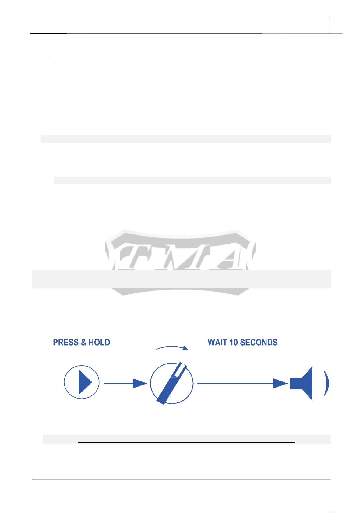
9.2. RESETTING THE COUNTER IN THE ALARM SYSTEM / in V20LA, V25LA,
V40, V80, V120/
The counter in the alarm system needs to be reset each time the UV lamp is
replaced.
a) Disconnect from power supply.
b) Replace the UV lamp –see pt. 9.1. REPLACEMENT OF THE UV LAMP.
c) Connect device to power supply (power switch should be turned off).
d) Press and hold the right button on the display for about 10 s.
01
NACISNĄĆ I PRZYTRZYMAĆ OK
CZEKAJ 10 SEKUND
e) Turn on the device while still holding the right button on the display.
To reset the counter the UV lamp must be connected and fully functional.
f) A short audible signal will confirm the resetting of the counter.

TMA
V9 –V120
15
TMA | Białostoczek 26,gm.Zabłudów,15-592 Białystok; Poland ; VAT PL5420008413; GIOŚ: E0021166WZ;
Tel. +48 857431246
9.3. REPLACEMENT AND CLEANING OF THE QUARTZ SLEEVE /FRAGILE
AND BRITTLE/
(graphic instructions at the and of the manual)
a) Disconnect the power supply,
b) Cut off the liquid flow through the chamber,
c) Remove the water from the chamber,
d) Allow for the lamp to cool down from operating temperature,
e) Remove the UV lamp from the sleeve / see pt. 9.1 /.
f) Unscrew the steel muff using the special spanner,
g) Take off the washer and o-ring from the quartz sleeve,
h) Pull out the quartz sleeve from the sterilizer chamber,
i) Every time the UV lamp is replaced, if it is necessary to clean the quartz sleeve, use common
glass cleaners and dry thoroughly the interior of the sleeve.
j) A new o-ring must be used each time the UV lamp is replaced.
k) Place the sleeve in the chamber of the sterilizer, put on a new o-ring and a washer,
l) Hand tighten the muff with the new o-ring. Use provided spanner to retighten the muff,
m) Open the shut-off valves slowly to pressurize the chamber and watch for leaks at the o-ring,
9.4. TROUBLESHOOTING
Problem
Cause
Action
Burned out UV Lamp.
End of lamp life caused by
number of working hours or
number of on-off cycles.
Disconnect the device from the power
supply.
Replace the UV lamp.
Burned out UV Lamp.
Water inside quartz
sleeve.
Muff not tightened
sufficiently.
Worn out o-ring.
Disconnect the device from the power
supply.
Take quartz sleeve out, dry interior,
change o-ring, and assemble back.
Tighten muff. Replace the UV lamp.
UV lamp electrode glows
red or yellow.
Damaged or depressurized
UV lamp.
Disconnect the device from the power
supply.
Replace the UV lamp.

TMA
V9 –V120
16
TMA | Białostoczek 26,gm.Zabłudów,15-592 Białystok; Poland ; VAT PL5420008413; GIOŚ: E0021166WZ;
Tel. +48 857431246
10. Spare parts list
V SERIES UV WATER STERILIZER
NO.
TITLE
V9–V120 –SPARE PARTS LIST
3
9
3
24
18
11
7
5
6MODELV120
No.
PART
No.
of
pcs.
V9
V12
V20/
20LA
V25/
V25LA
V35
V40
V80
V120
1
STRAIN RELIEF
1 pc.
02.01
02.01
02.01
02.01
02.01
02.01
02.01
02.01
2
LAMP HOOD
1 pc.
02.02.01
02.02.01
02.02.01
02.02.01
02.02.01
02.02.01
02.02.01
01.02.02
3
MUFF
1 pc.
03.04
03.04
03.04
03.04
03.04
03.04
03.04
01.04.02
4
MUFF O-RING
1 pc.
02.03.01
02.03.01
02.03.01
02.03.01
02.03.01
02.03.01
02.03.01
01.03.01
/2pcs./
5
WASHER
1 pc.
02.05
02.05
02.05
02.05
02.05
02.05
02.05
01.05
6
O-RING
1 pc.
02.06
02.06
02.06
02.06
02.06
02.06
02.06
01.06
7
SOCKET
1 pc.
03.08
03.08
03.08
03.08
03.08
03.08
03.08
03.08
8
UV LAMP
1 pc.
09.07
08.07
08.07
10.07
10.07
10.07
11.07
12.07
9
QUARTZ SLEEVE
1 pc.
06.09
08.09
08.09
10.09
10.09
10.09
10.09
12.09
11
DRAIN VALVE
1 pc.
-------
---------
01.12
-------
01.12
01.12
01.12
01.12
TMA
V9 –V120
17
TMA | Białostoczek 26,gm.Zabłudów,15-592 Białystok; Poland ; VAT PL5420008413; GIOŚ: E0021166WZ;
Tel. +48 857431246
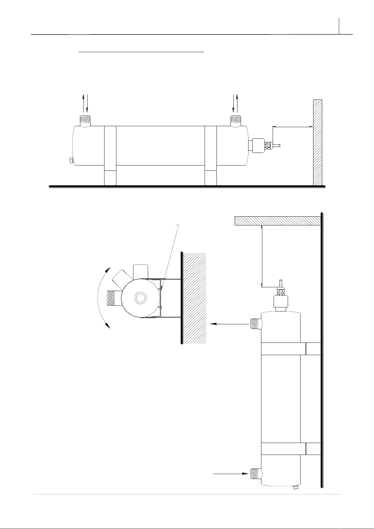
11. Graphic assembly instructions
11.1. ASSEMBLY OF THE STERILIZERS WITH BRACKETS –
V20,V20LA,V35,V40, V80, V120
M
M
WHEN THE STERILIZER IS MOUNTED
HORIZONTALY THE INLET END OUTLET CAN
BE LOCATED AT EITHER END.
M - DISTANCE NEED FOR
REPLACMANT OF THE UV LAMP
OUTLET
INLET
WHEN THE STERILIZAR IS MOUNTED
VERTICALY OR AT ANY OTHER ANGLE,
THE OUTLET HAS TO BE LOCATED AT
THE TOP OF CHAMBER
BRACKETS ENABLE THE ADJUSTMENT
OF THE CHAMBER POSITION
FOR THE NEEDS OF INSTALLATION.
1.LOOSEN THE SCREW AND ADJUST
THE POSITION OF THE CHAMBER FOR
THE INSTALLATION NEEDS
2.TIGHTEN THE SCREWS.

TMA
V9 –V120
18
TMA | Białostoczek 26,gm.Zabłudów,15-592 Białystok; Poland ; VAT PL5420008413; GIOŚ: E0021166WZ;
Tel. +48 857431246
11.2. ASSEMBLY OF THE ELECTRICAL ENCLOSURES IN V20LA, V25LA,
V40, V80, V120
Option I
Option I
Option II
Option II

TMA
V9 –V120
19
TMA | Białostoczek 26,gm.Zabłudów,15-592 Białystok; Poland ; VAT PL5420008413; GIOŚ: E0021166WZ;
Tel. +48 857431246
11.3. ASSEMBLY OF V9, V12, V25, V25LA

TMA
V9 –V120
20
TMA | Białostoczek 26,gm.Zabłudów,15-592 Białystok; Poland ; VAT PL5420008413; GIOŚ: E0021166WZ;
Tel. +48 857431246
11.4. ASSEMBLY OF V20, V20LA, V35, V40, V80
This manual suits for next models
10
Table of contents
Other TMA Laboratory Equipment manuals


Popular Laboratory Equipment manuals by other brands

Barnstead International
Barnstead International Cimarec series Operation manual and parts list

Mi-T-M
Mi-T-M AW-3000-0000 manual

URG
URG URG-3000N Operation manual

Noraxon
Noraxon Ultium 808 user manual

Terra Universal
Terra Universal Cleanroom Airlock Installation and operating guide

Leica
Leica CM1520 Instructions for use


