TMAX Digital E-BOARD PST05-4310 User manual
Silverado/Sierra
-
2019 POWER BOARD
Silverado/Sierra
2019
POWER
BOARD
Silverado/Sierra-2019
POWER BOARD
INSTALLATION
INSTALLATION
GUIDE
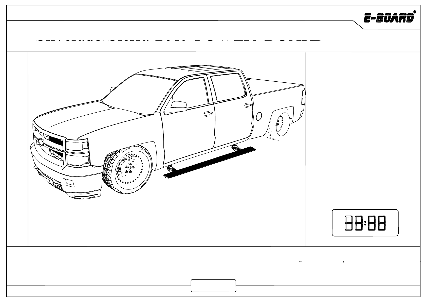
APPLICATION :Silverado/Sierra 1500/2500/3500 EXT/Double Cab 2019
INSTALLATION TIME
PRODUCT NUMBER :PST05-4310
Silverado/Sierra 1500/2500/3500HD Crew Cab 2019
①5mm Hex Key Wrench (Allen Wrench)
②
12mm Socket S
p
anne
r
TOOLS REQUIED :
PST05-4410
②
p
③12mm Ratchet Wrench
④Pry Tool ⑤Wire Cutter/ Stripper
⑥Vinyl Tape ⑦Screw Driver
www.tmax.biz
Silverado/Sierra-2019
Contents
Product Technical Specification.............02
Product Packing List...............................03
Mechanical Installation...........................06
Electrical Installation..............................11
Maintenance............................................21
Warranty Card.........................................23
Warranty
Card.........................................23
The product is developed and produced by T-MAX, and the related patents are blow.
Patents:US8
,
469
,
380
;
US9
,
656
,
609
;
US9
,
308
,
870
;
US9
,
688
,
205
;
US9
,
669
,
766
01
,,; ,,; ,,; ,,; ,,
www.tmax.biz

Silverado/Sierra-2019
Product Technical Specification
Rated Voltage: 12V
Specified Load: ≤350kg
Gross Weight: PST05-4310 34.8kg
PST05-4410 36kg
Forward extension size: 157mm
(Horizontal distance between the edge of power
board and the vehicle door when the board extends)
Board falling dimension: 288mm
(Vertical height difference between the edge of
power board and the vehicle door while board
extending.)
extending.)
(Both dimensions of forward and falling are
theoretical, which may vary due to uncertainties
such as installation error, manufacturing errors of
vehicle bottom and etc )
vehicle
bottom
and
etc
.
)
Note:Impact load is not allowed.
02
www.tmax.biz
Please make sure the children and the aged will keep 20cm safe distance while power board is working to avoid any
b
ump or jam.
Silverado/Sierra-2019
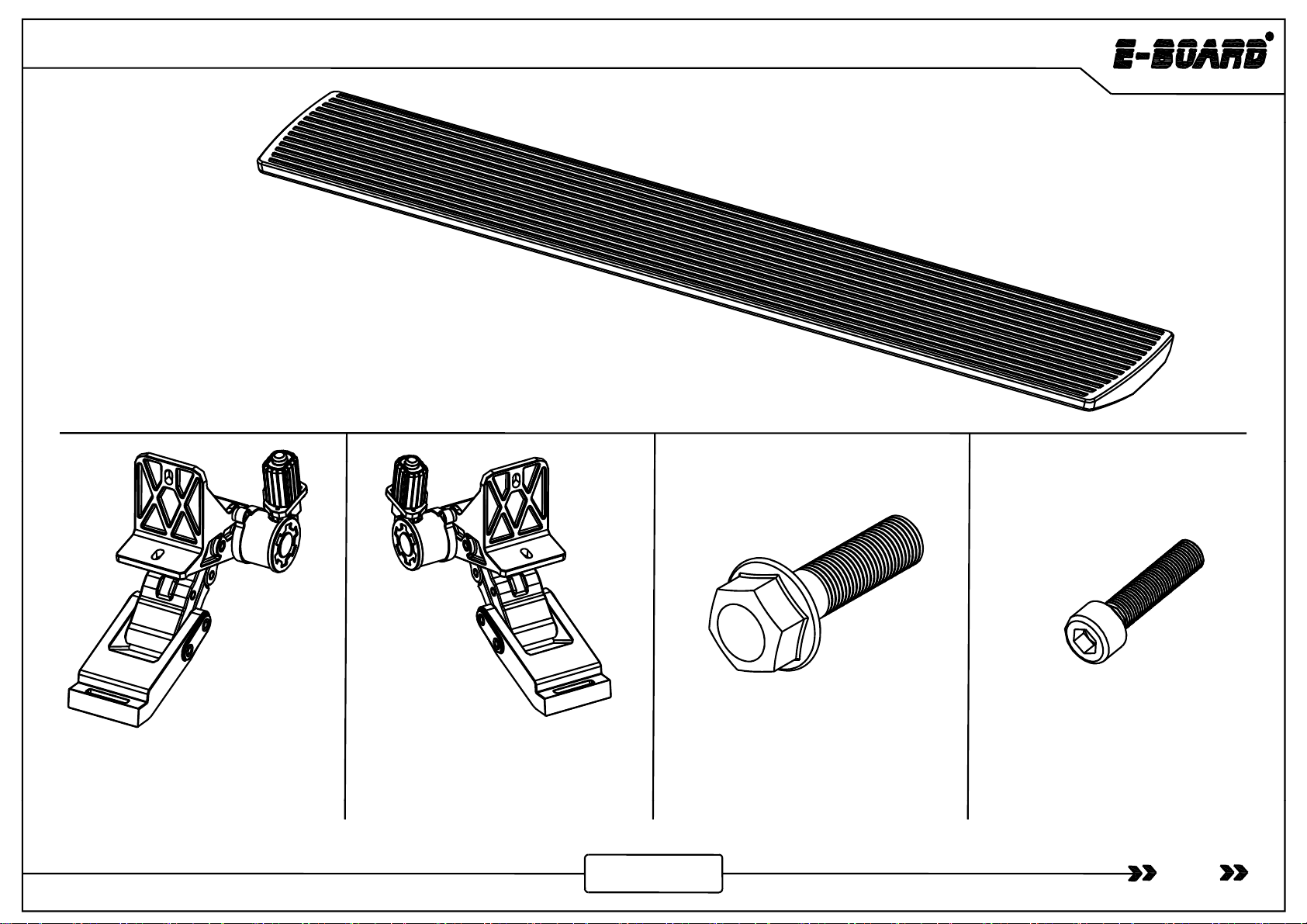
Product Packing List
Product
Packing
List
①
Board Assembly
×
2
①
-
Board
Assembly
×
2
②- Front Motor Linkage Left ×1
Rear Motor Linkage Left ×1
6114100 1L
③- Front Motor Linkage Right ×1
Rear Motor Linkage Right ×1
6114100 1R
④- Hexagon Flange Bolt ×8
QC/T340-1999 M8×30
⑤- Socket Cap Screw ×8
GB/T70.1-2000 M6×25
03
www.tmax.biz
6114100
.
1L
6114100
.
1R

Silverado/Sierra-2019
⑧-Wire Tie×25
GB/T22344-2008 5×300
⑥- Hexagon Flange Bolt ×2
QC/T340-1999 M8×25
⑦- Controller Assembly
6114100.4.4ZJ
Ma
g
net
⑪-LED Lamp×4
6161100 4 8
⑨-Fuse×2⑫- Power Board Switch×1
6124151 4 9
g
⑩- Wired Magnetic Induction
Module
×
2
04
6161100
.
4
.
8
(Optional)
6124151
.
4
.
9
www.tmax.biz
Module
×
2
- Magnet ×4
Silverado/Sierra-2019
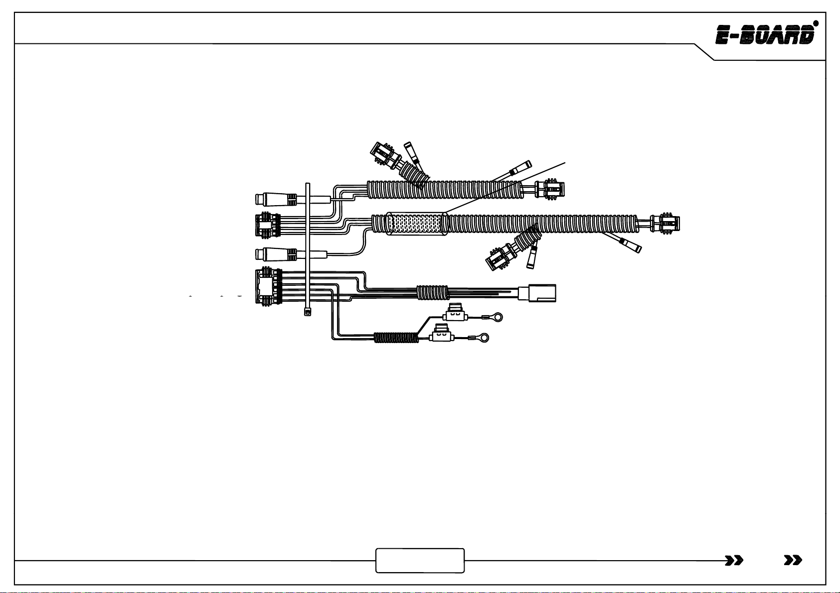
Four
core waterproof plug
Two-core plug (red)
Protection tube for high
temperature and burning
Six-core water
p
roof
p
lu
g
Four
-
core
waterproof
plug
Two-core plug (black)
(Positive-Red)
(Negative-Black)
ppg
⑬
⑬
- Control Input Wire ×1 6120100.4.1
05
www.tmax.biz

Silverado/Sierra-2019
hil lli
Mec
h
an
i
ca
l
Insta
ll
at
i
on
Installation
ii
As shown in the picture, these are the two
installation positions on the left side of the
p
os
i
t
i
on
Installation Position On the Left Side vehicle, and the installation mode of the front and
rear linkage are same .
06
www.tmax.biz

Silverado/Sierra-2019
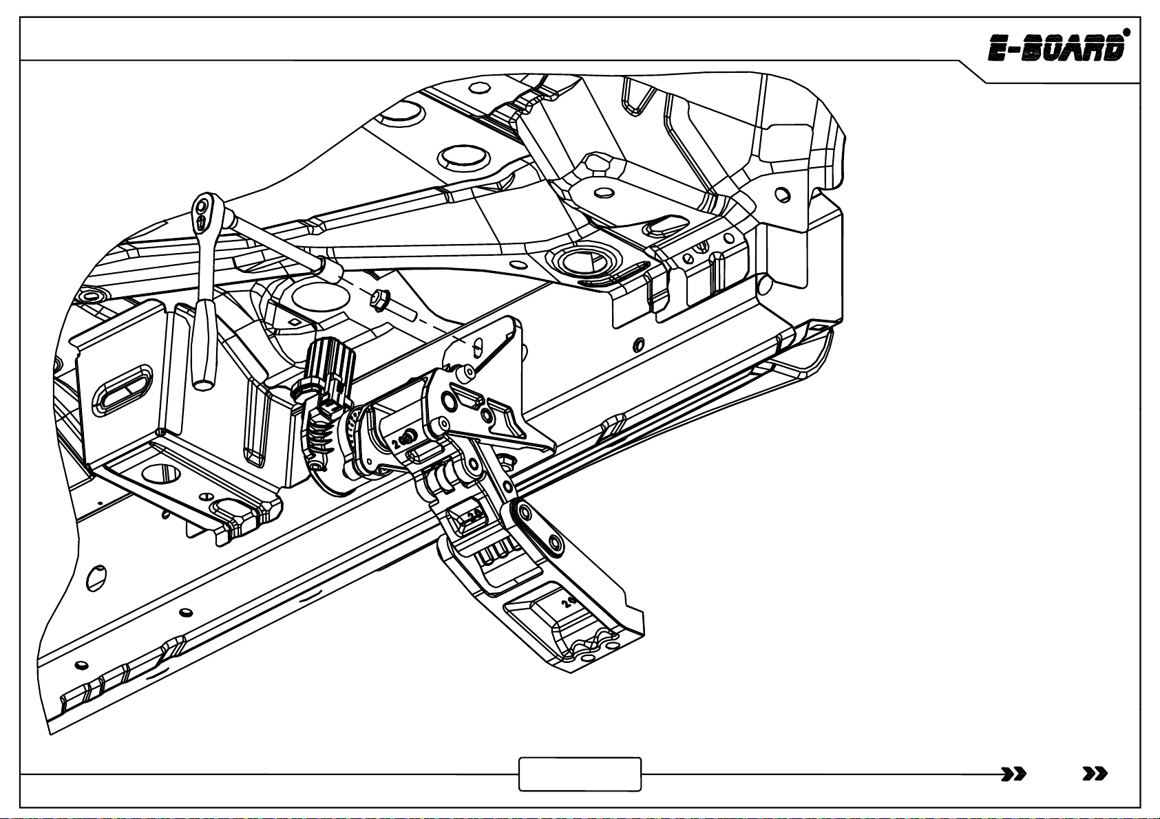
M8×30 Hexagon Flange Bolt
Installation of Front Motor Linka
g
e Left
07
g
www.tmax.biz
Silverado/Sierra-2019
S1S
hbl i hhl
Front left of the vehicle
S
tep
1
:
S
crew t
h
e
b
o
l
ts
i
n t
h
e
h
o
l
es
shown as the picture ,then tighten them
(Tighten torque is 35 Nm).
08
www.tmax.biz

Silverado/Sierra-2019
Step 2: Screw the bolts in the holes
shown as the picture ,then tighten them
(Ti
g
hten tor
q
ue is 35 Nm).
gq
Rear left of the vehicle
09
www.tmax.biz

Silverado/Sierra-2019
Socket Cap
Screw M6×25
The installation of the right side for motor linkage
and board is referenced to the left side.
Step 3: Install the board and adjust the T- nut to make the
two end faces of the board reach to an appropriate
iti Th M6
×
25
kt
f
10
www.tmax.biz
and
board
is
referenced
to
the
left
side.
pos
iti
on.
Th
en use
M6
×
25
soc
k
e
t
cap screws
f
or
connecting and tightening (Tighten torque is12Nm).
Silverado/Sierra-2019
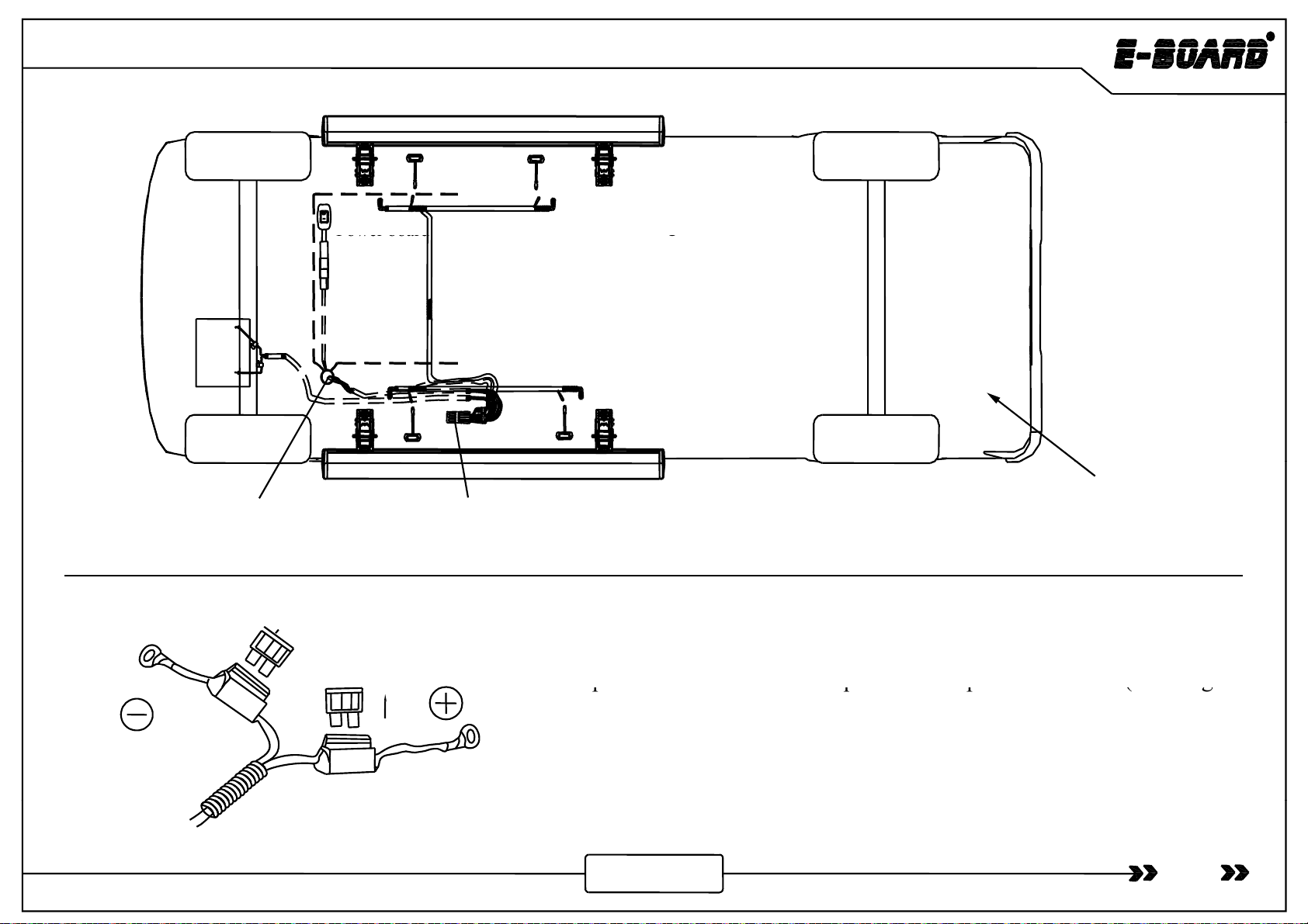
4.Connect white and brown si
g
nal wire
Electric
Installation by
Magnetic Control
Power board
g
with wired magnetic induction module .
Power
board
switch
1. Pull out the fuse and
connect the battery wire.
Battery
2. Connect the control wire and arrange all function
wires to the pointed positions.
5. Insert back the fuse and
sort out the wires.
Battery
3. Connect motor wire and LED lamp
wire.
Chassis on the right
The signal wire and power board switch pass
into the vehicle through the hole.
Controller
Ste
p
1: Find out the control in
p
ut wire and
p
ull out the fuse
(
ensurin
g
p
p
p(g
circuit safety during installation) and connect the positive and
negative pole of wire harness to vehicle battery respectively.
Note: Control wire can not be modified privately.
11
www.tmax.biz
Silverado/Sierra-2019
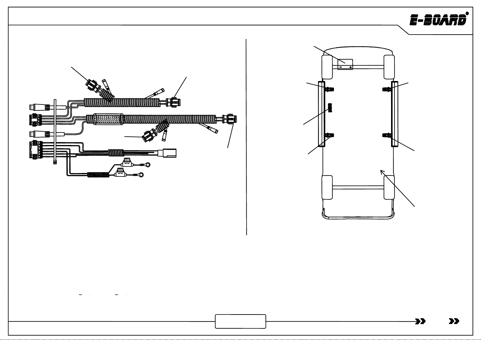
Front
Front
Right Rear
Right
Battery
Front
Ri h
Front
Controller
Ri
g
ht
Lef
t
Fron
t
Left
Rear
Left
Rear
Right
Rear
Left
Figure 1 Figure 2
Left side
(upward view)
Figure 1 is the wire harness diagram and figure 2 is the installation diagram.
When install the wire harness, make sure the four connectors are connected with the four motor linkages by
“front ri
g
ht
,
rear ri
g
ht
,
front left and rear left”.
12
www.tmax.biz
g, g,
Silverado/Sierra-2019
Controller Assembly
M8×25 Hexagon Flange Bolt
Step2 :As shown in the picture, install the controller assembly by two
M8
×
25
hexagon
flange
b
olts and tighten them (Tighten torque is 35Nm)
13
www.tmax.biz
M8
×
25
hexagon
flange
b
olts
,
and
tighten
them
(Tighten
torque
is
35Nm)
.

Silverado/Sierra-2019
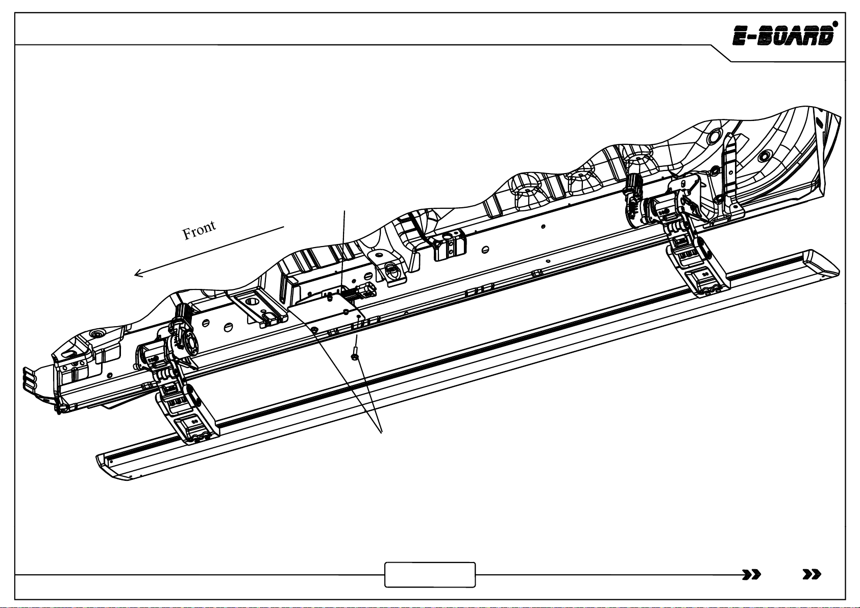
Ft
F
ron
t
Chassis on the right
Step 3:The arrangement of motor wire: Arrange the motor connection wire along the beam as
shown in the picture, the motor wire plug extends to motors of linkage. At least , adjust the wire
harness to make sure it is tidy and beautiful.
The other side uses the same way for installation.
14
www.tmax.biz
Silverado/Sierra-2019
A -pillar panel
Brown signal wire
White signal wire and
power board switch wire
Sill panel
Power board
Figure 2
Sill
panel
switch
Figure 1 Figure 3
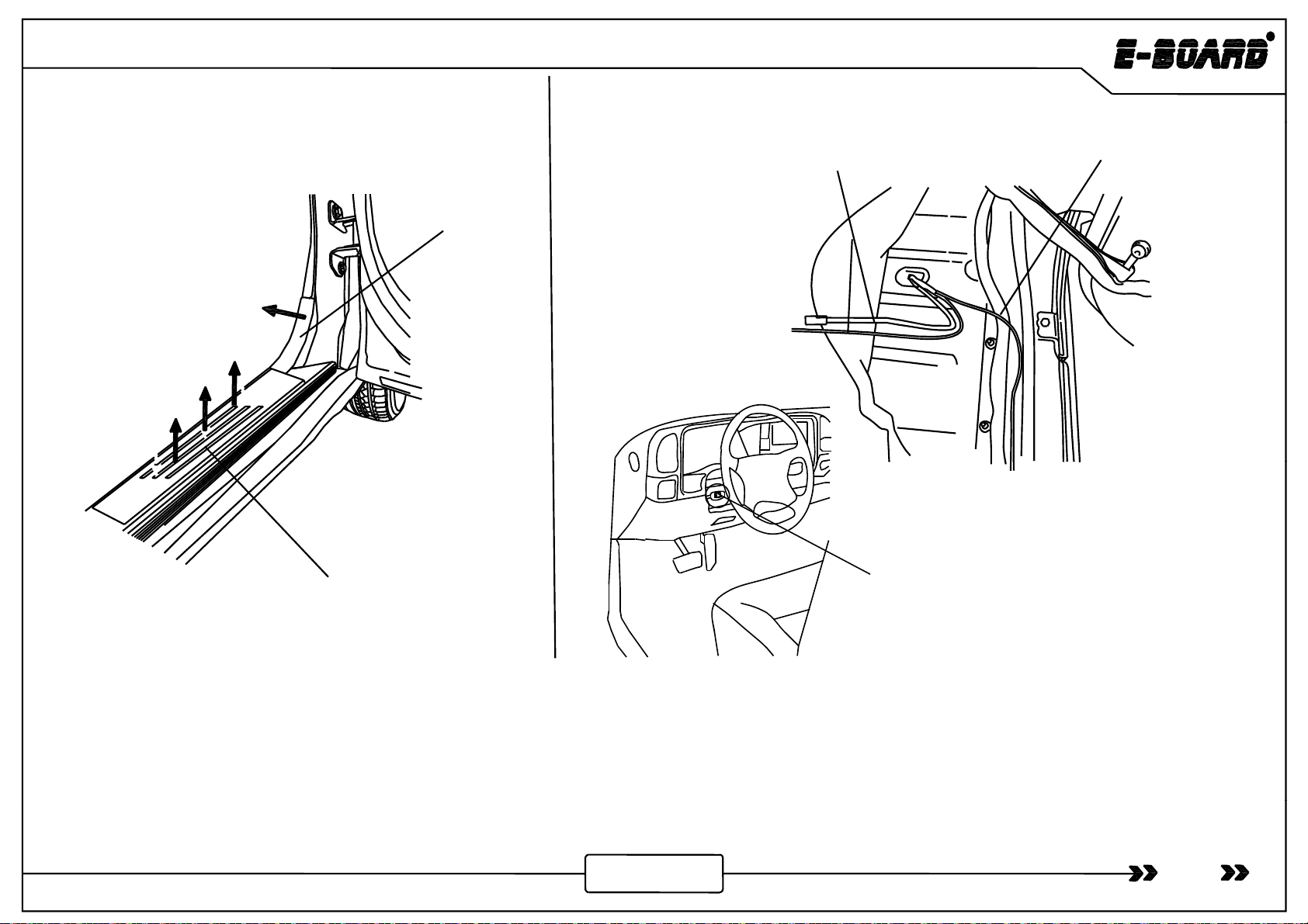
Step 4: Connection of signal wire: Pry the sill panel and A-pillar panel on the left above . Pull the brown signal wire into the vehicle
through the
rubber grommet of chassis on the right side Then the white signal wire extends to the left side of the vehicle unde
rthe
15
www.tmax.biz
through
the
rubber
grommet
of
chassis
on
the
right
side
.
Then
the
white
signal
wire
extends
to
the
left
side
of
the
vehicle
unde
r
the
carpet, and stick the Power board switch to the left side under the steering wheel.

Magnetic Inductor Installation
Silverado/Sierra-2019
BAC
Induction part C
Induction part C Wire Harness Magnetic Inductor
B-pillar on the
right
side (open
B
right
side
(open
the B-pillar
panel)
Itthd ili
Tighten the nut connecting
Remove the adhesive tape at
the back of C and stick one
A
Brown signal wire on
the right side
Earthing stud
D (Negative)
I
nser
t
th
e
d
oor s
i
gna
l
w
i
re
into A.
Tighten
the
nut
connecting
B and ground terminal of
door pillars.
the
back
of
C
,
and
stick
one
end on one side of the door
pillars.
Step 5:Open the B-pillar panel on the right side of the vehicle ,
expose the above part (as shown above), connect the brown
signal wire to terminal A of magnetic inductor, loosen the
hi
d
Dfk il
Bh
hi
Stick the other end to
the other side of
vehicle door pillars. Stick the magnets to the inner side of the vehicle
door and keep their positions corresponding to C.
eart
hi
ng stu
d
D
,connect
f
or
k
type term
i
na
l
B
to t
h
e eart
hi
ng
stud , and then tighten the earthing stud. Stick the induction part
C to the both side of B-pillar, stick the magnet on the inside of
vehicle door which is corresponding with induction part. The
if
hi
il
i
d
i
hidi
Magnet Magnet
16
connect
i
on o
f
w
hi
te s
i
gna
l
w
i
re an
d
w
i
re
h
arness
i
n
d
uct
i
on on
the left side are same with the installation of the right side. Instruction: The magnet position after closing the door is shown as above picture.
www.tmax.biz

Silverado/Sierra-2019
Step 6:Sort out the wire harness and close the panels. The installation of white signal wire on the left side is same
with the ri
g
ht side .
17
g
www.tmax.biz
Silverado/Sierra-2019
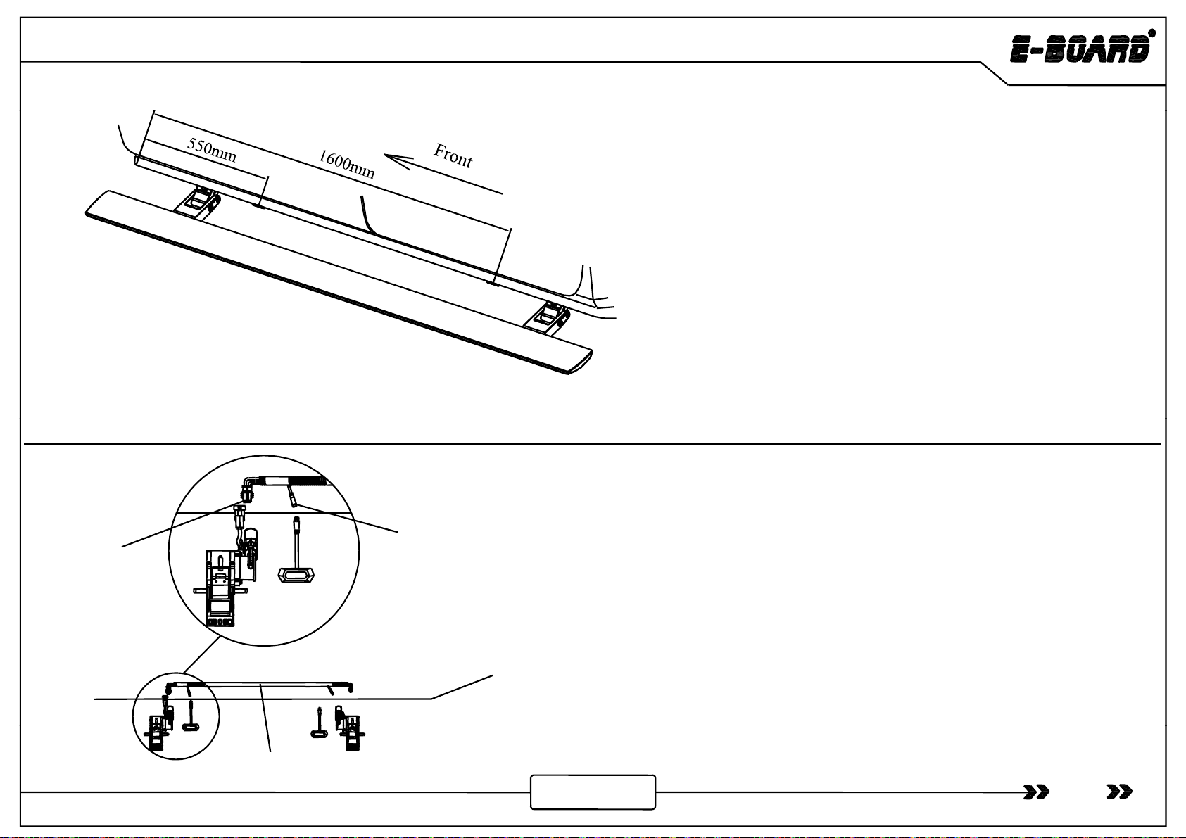
Step 7: Installation of LED lamp : Tear off the
double-sided adhesive tape behind the LED lamp
andstickitto
the thin all blo the apron The
and
stick
it
to
the
thin
w
all
blo
w
the
apron
.
The
distance from designated pasting position of front
and rear LED lamp to front door line of front door
is shown as the picture (The distance of the front
lamp is 550mm and the rear lamp is 1600mm)
lamp
is
550mm
,
and
the
rear
lamp
is
1600mm)
.
ll i f i h i h i
Connection of
motor connector
Step 8: Insta
ll
at
i
on o
f
motor w
i
re: As s
h
own
i
n t
h
e p
i
cture,
connect motor connector with the connector on motor wire.
At the same time, connect the LED lamp with LED lamp
connector on motor wire. Then fasten the wire harness on
hhilb b
i
ikh
i
h
Connection of
LED lamp
connector
t
h
e ve
hi
c
l
e
b
eam
b
y w
i
re t
i
e to ma
k
e t
h
e w
i
re
h
arness neat.
Same wire installation is for the other side.
18
Motor connection wire
www.tmax.biz
Silverado/Sierra-2019
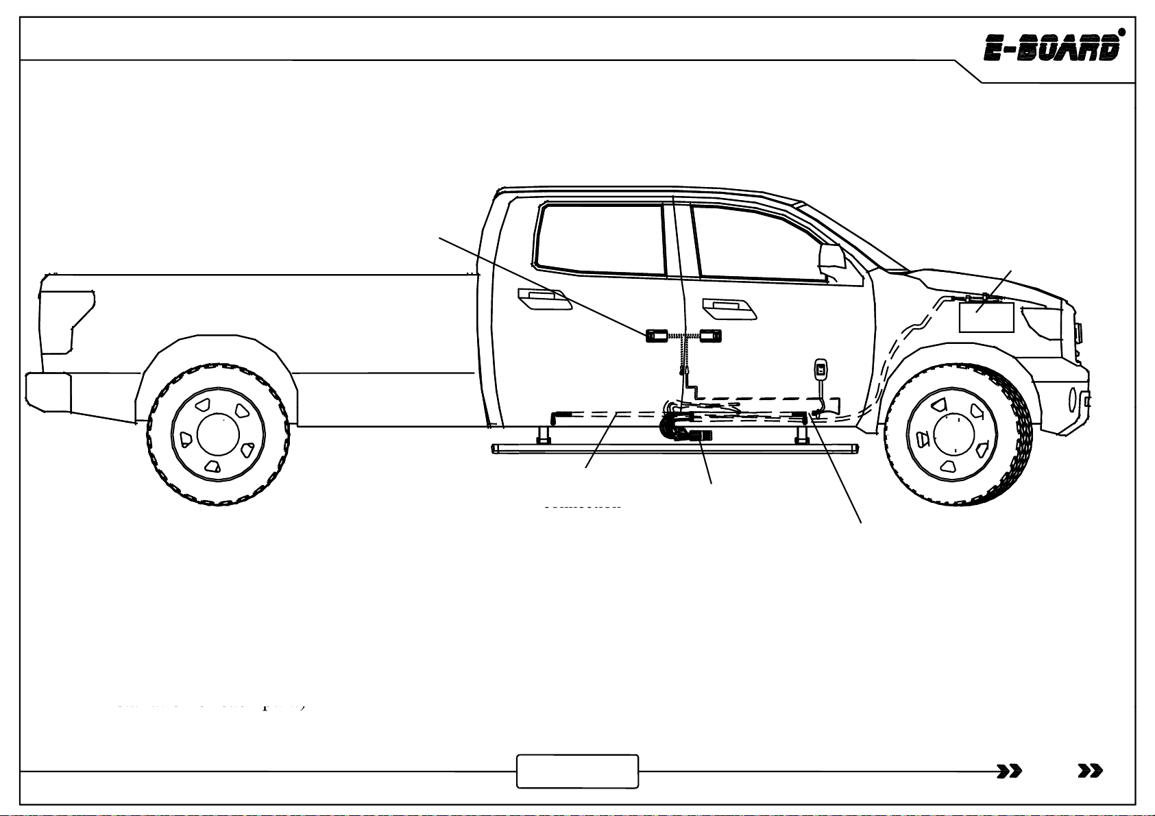
Summary of
Electric
P
art
Summary
of
Electric
P
art
Wired magnetic induction
module arrangement Battery
Power board
switch
Signal wire
arrangement
Motor wire
arrangement
Controlle
r
Motor wire
connection
Pull signal wire and Power board switch into the vehicle
connection
Step 9 : Check out the Power board switch of controller to make sure it is off. Insert back the fuse , arrange the wire
harness in order. Check if all the wires are connected well and test if the power board can work normally . If it can
work normally ,the board installation is completed. (If it can not work normally , please check the completeness of
installation
of
each part.)
19
www.tmax.biz
installation
of
each
part.)
This manual suits for next models
1
Table of contents
Other TMAX Digital Automobile Accessories manuals


