2 GROMMET
MICROPHONE
& BRACKET
or HANDSET
CONTROL
CABLE
(FRONT) (REAR)
123
456
789
*
0#
ABC DEF
GHI JKL MNO
PQ RS TUV WXYZ
...
.
BASE
PLATE
CONTROL HEAD BRACKET
(FRONT) (SIDE)
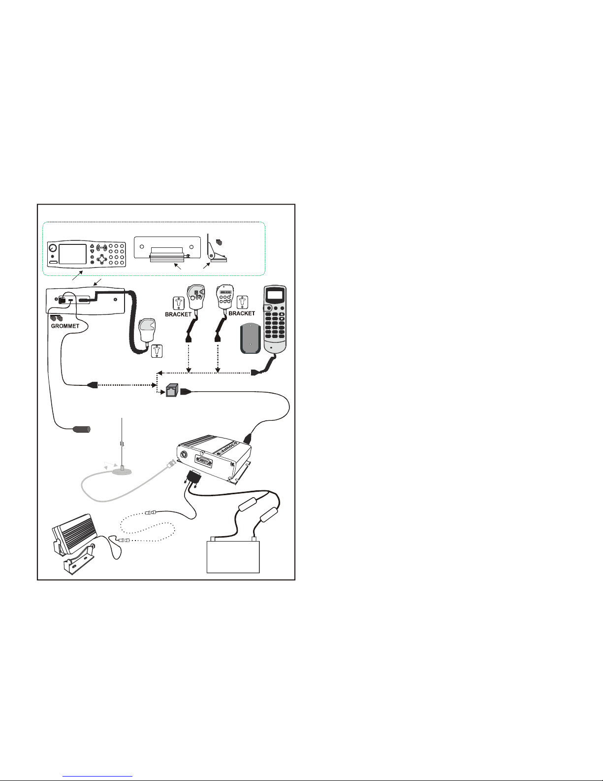
TRANSCEIVER INSTALLATION
The Transceiver is designed to be mounted in the luggage compartment or under the front
seat. Do not cover the transceiver with carpet, mats or luggage.
Locate the Transceiver in the desired position. A minimum clearance of 20mm around the
Transceiver is recommended to ensure adequate airflow.
Secure the Transceiver in position using the supplied screws. Alternatively, if the Quick
Release Mounting option is used, mount the Cradle in the desired position and clip the
transceiver into the Cradle.
POWER & OPTION CABLING
Run the LT-Cable from the installed Transceiver to the Vehicle Battery terminals. Ensure
the cable is routed with enough slack so that it is not under tension in its travel. Allow an
extra 0.5m before cutting off excess. Ensure any holes that the cable passes through are
de-burred and fitted with a grommet.
Fit the Fuses in both +VE and -VE wires of the cable pair. The Fuses are to be fitted within
approximately 0.5m of the Battery before the cable has contact with other cables or the
vehicle body. Only 12V, 10Amp, fast blow fuses should be used.
On the DB15 Power/Speaker connector, connect Pins 3 and 14 as follows:
Pin 3 (Ignition Sense) Connect Pin 3 to the Ignition Switch wiring such
that +12V is applied when the ignition is switched
ON and is disconnected when the ignition is
switched OFF.
Pin 14 (Handsfree Mic) Refer to separate Installation Instructions for
connection of the Handsfree Microphone.
CONTROL HEAD/HANDSET/MICROPHONE INSTALLATION
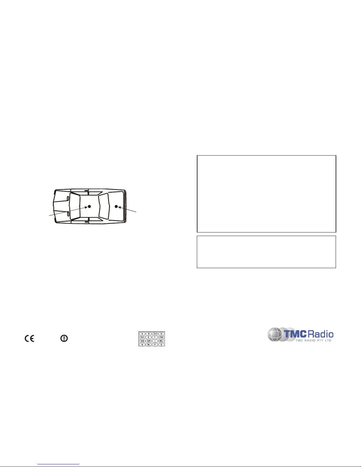
The Control Head and/or Microphone/Handset stowage bracket should be mounted so that
the display and control buttons are readily visible and accessible to the driver when
constrained by a seatbelt. Ensure that these locations are chosen such that the equipment
cannot cause injury in the event of an accident. Ensure that all in-cab equipment is mounted
outside the passenger’s safety zone. Ensure that there is adequate room for cables to exit
the Control Head without interference.
Do not locate the Control Head/Handset/Microphone on the top of the dashboard or in direct
sunlight as the temperature of exposed surfaces may rise over 100°C in the sun.
Locate the Handset/Microphone Bracket where the driver can readily remove or stow the
Handset/Microphone. Ensure that the curly cord is not stretched when the unit is stowed on
the Bracket.
Note: The Handset/Microphone Bracket is proximity sensitive. Certain radio operations
rely on the Handset/Microphone being correctly stowed in the stowage bracket
when it is not being used.
The Control Head Bracket may be fitted onto the SRM9030 in two orientations, allowing
extra mounting options. Determine the desired position and secure the Control Head
Bracket Base Plate in position.
Connect the Microphone and Transceiver Cables (refer to diagram). Secure the SRM9030
to the Mounting Bracket. Locate and secure the Mounting Bracket to the Base Plate.
If the Optional Mic/Control Head Extension Cable and Junction Box are used, locate and
secure the Junction Box in a safe convenient location using the supplied fittings.