TMC TMC 30E User manual

Injection Molding Machine
Operation ManualV3.0
For System TM11
TMC Technology Corp.
No.726, Jieh Shou Road, Sec. 2, Pa Teh,
Taoyuan, Taiwan
Tel : 866-3-3688127
Fax : 886-3-3684959
Website : Http://www.tmcint.com

InjectionMoldingMachine Chapter0
0-1 V3.0
Content Ver. 3.0
Chapter 1: Safety
1. Operator safety protection……………..……………………………………………………… 1-1
1.1 Electrical ............................................................................................................................. 1-2
1.2 Hydraulic safety device....................................................................................................... 1-2
1.3 Machinery safety device .....................................................................................................1-3
2. Safety operation of machine …...……………………………………………………………... 1-4
2.1 Operation environment........................................................................................................ 1-4
2.2 Disposal of scrap products or waste.................................................................................... 1-4
2.3 Clamping unit...................................................................................................................... 1-4
2.4 Injection unit ....................................................................................................................... 1-4
2.5 Hydraulic unit...................................................................................................................... 1-5
2.6 Electrical unit...................................................................................................................... 1-5
3. Safety labels and alarm devices...……………………………………………………………... 1-6
3.1 Definition of labels.............................................................................................................. 1-6
3.2 Adhering position................................................................................................................ 1-6
3.3 Alarm light and buzzer........................................................................................................ 1-8
3.4 Escape when trapped in machine........................................................................................ 1-8
4. Machine maintenance warranty……………………………………………………………….. 1-8
Chapter 2:Machine specifications
1. Machine specifications………..…………………………………...………………………….. 2-1
2. Machine dimensions………….……………………………………………………………….. 2-4
3. Operating position…………………………………………………………………………….. 2-5
4. Safety devices layouts…..…………………………………………………………………….. 2-6
5. Position of signs and labels…..……………………………………………………………….. 2-7
Chapter 3: Preparation of installation and test running
1. Placing of the machine............................................................................................................... 3-1
2. Foundation of the machine......................................................................................................... 3-1
3. Transportation ............................................................................................................................ 3-2
3.1 Transportation preparation..................................................................................................3-2
3.2 Process of transportation..................................................................................................... 3-2
4. Leveling……………………………………………………………………………………….. 3-6

InjectionMoldingMachine Chapter0
0-2 V3.0
5. Adjusting of mounting pad………………………..………………………………………….. 3-7
6.Ventilation……………………………………..……………………………………………….. 3-8
7. Preparation before operation………………………………………………………………….. 3-9
7.1 Power supply....................................................................................................................... 3-9
7.2 Cooling water...................................................................................................................... 3-10
7.3 Main power/water connection position............................................................................... 3-10
7.4 Material............................................................................................................................... 3-10
7.5 Hydraulic oil, lubrication oil and grease............................................................................. 3-11
7.6 Operating temperature and humidity .................................................................................. 3-11
8. Pre-operation checkpoints…………………………………………………………………….. 3-12
4.1 Check before power ON...................................................................................................... 3-12
4.2 Check before motor starting................................................................................................ 3-12
4.3 Motor starting inspection .................................................................................................... 3-12
4.4 Check the mold condition ................................................................................................... 3-14
Chapter 4: Operation
1. Operation panel………………………………………………………………………………... 4-1
1.1 Screen /function selection key............................................................................................ 4-1
1.2 Number/alphabet key.......................................................................................................... 4-1
1.3 Direction/screen operation instruction key......................................................................... 4-1
1.4 Manual operation switch.....................................................................................................4-1
2. Screen layout and operation…………………………………………………………………… 4-3
2.0 Main page of operation screen............................................................................................ 4-5
2.1 Main page of operation screen............................................................................................ 4-7
2.2 Machine monitoring screen................................................................................................ 4-8
2.3 Clamp open/close setting....................................................................................................4-9
2.4 Clamping parameters.......................................................................................................... 4-11
2.5 Ejector setting..................................................................................................................... 4-13
2.6 Ejector parameter................................................................................................................ 4-15
2.7 Corepull setting................................................................................................................... 4-17
2.8 Corepull parameters............................................................................................................ 4-19
2.9 Injection setting .................................................................................................................. 4-20
2.10 Injection parameters........................................................................................................... 4-22
2.11Injection closed loop control .............................................................................................. 4-24
2.12 Charge/Carriage setting..................................................................................................... 4-26
2.13 Charge/Carriage parameters .............................................................................................. 4-28
2.14 Temperature setting........................................................................................................... 4-30
2.15 Temperature parameters .................................................................................................... 4-31
2.16 Molding data store…….………………………………………………………………... 4-33
2.17 SPC data …………………………………………………………………………………. 4-34

InjectionMoldingMachine Chapter0
0-3 V3.0
2.18 Function setting/pressure testing ....................................................................................... 4-36
2.19 Production management .................................................................................................... 4-38
2.20 Automatic mold adjustment............................................................................................... 4-39
2.21 Automatic purge function.................................................................................................. 4-41
2.22 External I/O monitor.......................................................................................................... 4-42
2.23 Charge record..................................................................................................................... 4-46
2.24 Alarm record...................................................................................................................... 4-47
2.25 Maintenance check point................................................................................................... 4-48
2.26 Molding support................................................................................................................. 4-50
2.27 System self diagnostic function......................................................................................... 4-51
2.28 Internal IO monitor............................................................................................................ 4-52
2.29 T/C setting ......................................................................................................................... 4-53
2.30 Screen print........................................................................................................................ 4-54
3. Machine operation procedures ................................................................................................... 4-55
4. Start up…..……………………………………………………………………….…………... 4-55
4.1 Manual operation................................................................................................................ 4-55
4.2 Semi-automatic operation................................................................................................... 4-56
4.3 Fully automatic operation................................................................................................... 4-57
4.4 Emergency stop .................................................................................................................. 4-57
4.5 Alarm clearance.................................................................................................................. 4-57
4.6 Re-start after safety interlock devices were tripped ........................................................... 4-58
5. Molding operation…………………………………………………………………………….. 4-58
5.1 Preparation before molding operation ................................................................................. 4-58
5.2 Check before molding operation ......................................................................................... 4-58
5.3 Molding condition setting.................................................................................................... 4-59
5.4 Start molding ....................................................................................................................... 4-60
5.5 Change material or color change......................................................................................... 4-60
5.6 Store/read molding condition by memory card................................................................... 4-60
6. Machine shutdown procedures 4-61
Chapter 5: Trouble shooting
1. Mechanical unit……………………………………………………………………………….. 5-1
1.1 Motor can not be started...................................................................................................... 5-1
1.2 No clamp close.................................................................................................................... 5-1
1.3 No clamp open .................................................................................................................... 5-2
1.4 No ejector advance.............................................................................................................. 5-2
1.5 No ejector retract................................................................................................................. 5-2
1.6 No injection......................................................................................................................... 5-3
1.7 No suck back....................................................................................................................... 5-3
1.8 No charge............................................................................................................................ 5-4
1.9 No carriage advance and backward..................................................................................... 5-4

InjectionMoldingMachine Chapter0
0-4 V3.0
1.10 No mold adjustment........................................................................................................... 5-5
1.11 No automatic clamping force............................................................................................. 5-5
1.12 Core failure......................................................................................................................... 5-6
1.13 Temperature control abnormal........................................................................................... 5-6
2. Electric unit…………………………………………………………………………………… 5-7
2.1 Warning screen description................................................................................................. 5-7
2.2 Warning content and maintenance message indication ...................................................... 5-8
2.3 System message and description......................................................................................... 5-14
3. Hydraulic unit…………………………………………………………………………………. 5-15
Chapter 6: Maintenance
1. Safety device inspection………………………………………………………………………. 6-1
1.1 Electric safety...................................................................................................................... 6-1
1.2 Hydraulic safety .................................................................................................................. 6-1
1.3 Mechanical safety................................................................................................................ 6-1
2. Periodic inspection…………………………………………………………………………….. 6-2
2.1 Daily inspection items......................................................................................................... 6-2
2.2 Monthly inspection items....................................................................................................6-2
2.3 Halt-year inspection items................................................................................................... 6-2
2.4 Maintenance and check chart.............................................................................................. 6-3
3. Cleaning……………………………………………………………………………………….. 6-5
3.1 Screw removal/installation and cleaning ............................................................................ 6-5
3.2 Barrel removal/installation and cleaning ............................................................................ 6-6
3.3 Cooler removal/installation and cleaning............................................................................ 6-7
3.4 Hopper window glass replacement ..................................................................................... 6-7
3.5 Filter removal/installation and cleaning.............................................................................. 6-7
3.6 Water distributor removal/installation and cleaning........................................................... 6-8
4. Lubrication…………………………………………………………………………………….. 6-9
4.1 Toggle system lubrication.................................................................................................... 6-9
4.2 Grease lubrication ................................................................................................................ 6-10
4.3 Lubrication points and timing…………………………………………………………….. 6-11
4.4 Lubrication for die height adjustment gear……………………………………………….. 6-12
5. Spare parts…………………………………………………………………………………….. 6-13
Chapter 7: Adjustments
1. Mechanism adjustments……………………………………………………………………... 7-1
1.1 Adjustment of carriage center height.................................................................................. 7-1

InjectionMoldingMachine Chapter0
0-5 V3.0
1.2 Adjustment of moving platen shoes.................................................................................... 7-2
2. System adjustments.................................................................................................................... 7-3
2.1 Adjustment of transducer…………………………………………………………………. 7-3
2.2 Adjustment of proportional valve………………………………………………………… 7-5
2.3 Adjustment of motor overload protector…………………………………………………. 7-6
Appendix A
1 Hydraulic sequence ………………………………………………………… A-1
2 How to re-open clamp when it locked …………………………………………………. A-17
Appendix B
Notes on motion/no motion…………………. ……………………………………………… B-1
Appendix C: Robot Connection………………………………………………………………….. C-0
Appendix D: USB file operation…………………………………………..…………………….. D-0
Chapter 8:Drawings
1. Description of major component parts and their positions installed on the machine
1.1 View from operational side
1.2 View from rear operation side
2. Appearance dimension drawing
3. Screw/Barrel unit assembling drawing
4. Hydraulic circuit drawing
5. Hydraulic manifold drawing
5.1 Injection manifold
5.2 Clamp manifold
5.3 Ejector manifold
6. Oil pipes layout drawing
7. Electrical wiring diagram
8. Control box layout drawing

InjectionMoldingMachine Chapter1
1-0 V3.0
Chapter 1:Safety
1. Operator safety protection………..…... 1-1
1.1 Electrical device .............................. 1-2
1.2 Hydraulic safety device ................... 1-2
1.3 Mechanical safety device................ 1-3
2. Safe operation of machine………….. 1-4
2.1 Operation environment.................... 1-4
2.2 Disposal of scrap products or waste 1-4
2.3 Clamping unit .................................. 1-4
2.4 Injection unit.................................... 1-4
2.5 Hydraulic unit .................................. 1-5
2.6 Electrical unit................................... 1-5
3. Safety labels and alarm devices……… 1-6
3.1 Definition of labels........................... 1-6
3.2 Adhering position............................. 1-6
3.3 Alarm light and buzzer..................... 1-8
3.4 Escape when trapped in machine ... 1-8
4. Machine maintenance warranty.......... 1-8
InjectionMoldingMachine Chapter1
1-1 V3.0
Chapter 1:Safety
This machine has equipped with mechanical,hydraulic and electrical triple safety devices,
however,only qualified personnel by the user company can operate this machine, the user
company must have the operators to read and execute all safety rules to ensure safety.
Only manufacture or manufacture’s agent qualified technical personnel can perform
maintenance or repair works on the machine, the technical personnel must have sufficient
knowledge regarding all safety precautions and operating elements.
1 Operator safety protection
Daily inspections shall be performed in accordance with the maintenance and checklists
displayed upon the operation of the machine to ensure the safety of the operator and
machine.
V1: 0/ 0 0/ 0V2:
0/ 0P1: 0/ 0 P2:100.0mm
100.0mm110.0mm
1.0mm
ACTION STATUS
M:
02D05M07Y
10h250m10s
20°C3W
DAILY CHECK & MAINTENANCE
F2F1 F3 F4 F5 F6 F7 F8
MENU
17 MAINTEN. SUPPORT I/O
MAINT.
LIST
1.PUSH EMERGENCY BUTTON TO CHECK PUMP STOP.
3.CK. SAFETY DROP BAR MOVES SMOOTH.
4.CK. BARREL COVER IS FIXED.
5.CK. LUB. OF MOVING PARETS ARE OK.
10.CK.HYD.& LUB.OIL ARE ENOUGH.(NO RECYCLE OIL)
7.CK. COLD START PROTECT. TIME AND DANGER
8.CK. TEMP. SET OF HYD. OIL & COLLAR ARE OK.
9.CK IF PUMP HAS ANY NOISE.
6.CK. NO PARTS IS LOOSENED OR ABNORMAL.
11.CK. NO HOSE/PIPE IS LOOSENED/LEAKING.
12.CK. NO AIR IS BLENDED INTO HYD. SYSTEM.
13.CK. ALL GROUDINGS ARE CONNECTED OK.
14.CK. MOLD CLAMP ARE TIGHT.
15.CK. MOLD PROTECTION DEVICE IS OK.
2.CK.NO LEAKING IN HYD. SYSTEM.
1.CK.AND CLEAN HYD. FILTER.
3.CK.AND CLEAN OIL COOLER.
4.CK.NO MOVING PARTS ARE LOOSENED.
5.CK.AND CLEAN ELECTRIC CABINET.
6.TIGHT ALL WIRING TERMALS.
8.TEST PRESS. AND SPEED LINEARILITY.
7.CLEAN AND ADJUST ALL
9.CLEAN WASTE OIL.
HALF YEARLY CHECK AND MAINTENANCE
1.CK.PALTEN'S PARALLELISM.
2.CHANGE HYD. SYSTEM OIL.
3.CK.SCREW/BARREL FUNCTION WELL.
4.MACHINE LEVELING ADJUST.
MONTHLY CHECK & MAINTENANCE
LOG MOLD EXTERN
TEMP. SET OK. THERMOCOUPLES.
2.CK. I/O 101,103,109 FUNCTION BY OPEN/CLOSE DOOR.
Screen 1-1

InjectionMoldingMachine Chapter1
1-2 V3.0
1.1 Electrical device
1.1.1 Emergency button:Each machine is equipped with two emergency buttons located
respectively on the control panel and rear operation side. Upon emergency,press the
emergency button nearby. When the emergency condition is cleared,rotate emergency
button clockwise to release it.
1.1.2 Safety door switch:Change screen to EXTERNAL I/O screen,open/close all safety
doors and check corresponding I/O status,they must be normally ON/OFF.
Opening the front operation door,I/O 101,I/O 109 must be OFF (highlighting disappears),
opening rear safety door or other side doors,I/O 103 must be OFF. Close front door to have
I/O 101,I/O109 on,close rear door to have I/O 103 on.
1.1.3 Mold height limit switch:Upon pressing the minimum mold thickness limit switch,or
actuate the proximity switch,I/O 111 must be OFF;upon actuate the maximum mold
thickness switch,I/O 112 must be OFF
1.2 Hydraulic safety device
Inspect hydraulic safety valve V35 on clamping manifold ,when opening the front operation
door,I/O 101,109 must be OFF,and mold close is disabled at the time. For testing,unplug
the electrical plug of V35,and close the operation door then close mold manually,mold close
operation cannot be performed at the time.
Emergency
Button Emergency
Button
V35 Mold-clamping safety
valve

InjectionMoldingMachine Chapter1
1-3 V3.0
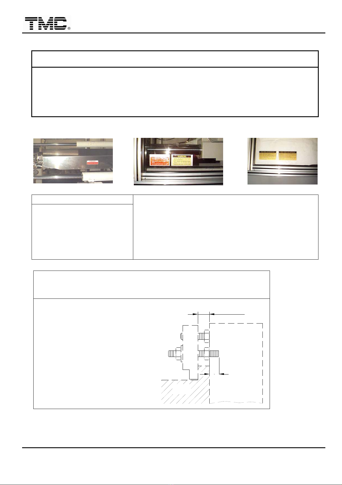
1.3 Mechanical safety device
A Open/close the front operation door,and check the action of drop bar plate for
smoothness.
B Barrel guard:check barrel cover,injection nozzle guard fixing screws.
Drop bar Barrel cover
Injection nozzle guard

InjectionMoldingMachine Chapter1
1-4 V3.0
2 Safe operation of machine
2.1 Operating environment
For a safety operating environments, personal protection devices are required; safety shoes
and other protection devices required by the user country regulations are necessary.
If the noise level of operation environment is over 80dB,protection device like ear-mask is
required.
User company is responsible to provide a well-lit space complied with local regulations and
dry and flat ground for operating.
2.2 Disposal of scrap products or wastes
Disposal of scrap products or wastes must follow local laws and regulations.
2.3 Clamping unit
★It is absolutely prohibited to remove any mechanical,hydraulic safety device or short circuit
of electrical safety limit switch.
★Please don’t extend your hands or any part of your body into areas protected by the safety
guard during operation.
★When it is necessary to adjust the mold on the machine,be sure to turn off pump motor;
power off and hang the sign [Don’t Turn On Power] on the power switch.
★Only authorized and qualified personnel are allowed to operate the machine.
★Prior to starting the machine,please confirm all the safety guards are at normal positions.
★After starting the machine,please confirm the normal operation of the safety gate.
★Please check if the mold is fixed tightly on the platens.
2.4 Injection unit
★Do not touch the barrel to avoid electrical shock or get burned.
★Do not step on the barrel guard to avoid get electrical shock or damage thermocouples.
★Do not remove the barrel guard.
★When it is necessary to remove barrel guard to replace the heater band,please power off
machine first and make sure barrel unit is cooled down before starting to work.
★Make sure the power is off when taking out the screw. Do not stand in the direction of
screw when it will be pulled out.
★When the melted material is still flowing out from the nozzle,do not clean the nozzle.
★Do not heat the plastic material exceeding its processing temperature,especially for the
PVC、POM which might generate gas.
★When the nozzle or barrel end cap is not installed,do not nor perform charge nor injection
operation.
★Upon cleaning inside of the hopper,make sure machine power is off.
★When PVC,POM or corrosive glass fiber added material are used,upon material change

InjectionMoldingMachine Chapter1
1-5 V3.0
or before machine shutdown,please use PP material to clean the barrel.
★Prior to move the carriage forward,be sure to close the mold.
2.5 Hydraulic unit
★Do not set pressure over the maximum system operation pressure according to machine
specification.
★Power off machine and wait for no residual hydraulic pressure before disassemble any
hydraulic or mechanical parts.
★When damage is found on the high pressure hose,replace it immediately;otherwise,
when the high pressure hose is ruptured,the high pressure hydraulic oil will erupt thus
causing injury to the personnel.
★The operation temperature of hydraulic oil is 35℃-50℃,continuous operation between 20
℃-55℃is allowed;however,when the temperature is below 20℃,please perform oil
pre-heat process to heat up the temperature,oil temperature less than 20℃will make the
system very unstable.
★When the hydraulic hose or valve is found loose,please tighten them up immediately thus
preventing oil leakage or other problems.
2.6 Electrical unit
★Turn the power off before opening the control cabinet to prevent electrical shock.
★Turn the power off before removing the barrel guard.
★Turn the power off before replacing the heater band.
★Turn the power off before wiring the circuits in the terminal box of heater band.
★Make sure the machine has been properly and independently grounded(earthed),phase N
shall not be in connection with grounding G.
★Make sure no water accumulated in the machine to prevent the water from getting into the
electrical control cabinet and result in electric leakage or damage on the machine.

InjectionMoldingMachine Chapter1
1-6 V3.0
3 Safety labels and alarm devices
3.1 Definition of labels
◇Safety label shall be adhered on/fixed to some corresponding positions to remind operators
of protecting their own safety.
◇Do not remove the safety labels or hide them behind other objects.
◇When the safety labels are old or damaged to such an extent that they are illegible,
please buy the new ones from our agent or distributor.
3.2 Adhering position
DAILYCHECK AND MAINTENANCE
1.CHECK IF LUBRICANT IS PLENTYAND CLEAN,AND ALL MOVABLE PARTS ARE
WELL LUBRICATED.
2.CHECK IF THERE IS PLENTY HYDRAULIC OIL.
3.CHECK IF EACH HYDRAULIC PRESSURE IS ACCURATE.
4.CHECK IF THERE ISANYABNORMAL NOISE ON HYD. SYSTEM.
5.CHECK IF BOLTS AND NUTS OF TIE ROD ARE LOOSEN.
6.CHECK THE COOLING SYSTEM.
7.CHECK IF THE EMERGENCY STOP BUTTON FUNCTION NORMALLY.
8.CHECK IF BARREL HEATING ELEMENTSAND TEMPERATURE CONTROLLER ARE
NORMAL.
WEEKLY CHECK AND MAINTENANCE
1.REMOVE HYDRAULIC OIL FILTER FOR CLEANING.
2.CHANGE HYDRAULIC OIL IF BUBBLES DIRT OR DEGENERATION ARE FOUND.
3.CHECK IF ANY LEAKAGE ON THE HYDRAULIC PIPING SYSTEM.
4.CLEAN THE INSIDE OF COOLING SYSTEM.
5.CHECK IF ANY MOVABLE PARTS ARE LOOSEN.
6.REMOVE THOROUGHLY ANY RESIN ADHERED TO THE HEATING ELEMENTS OR
ELECTRICAL WIRES ON BARREL.
7.CLEAN THE INSIDE OF ELECTRICAL CONTROL BOARDAND SWITCH BOX.
MAKE SURE THE WIRING TERMINALS ARE WELL FASTENED.
InjectionMoldingMachine Chapter1
1-7 V3.0
WARNING
1.WARNING OPERATORS NOT TO OPERATE MACHINE UNLESS THOUOUGHLY
INSTRUCTED ON SAFETY RULES AND OPERATIONS.
2.INSPECTAND CHECK OFF PROCEDURES FOR ELECTRIC,HYDRAULIC,AND
MECHANICAL SAFETY DEVICES.
3.MAKE SURE CLAMP CAN NOT BE CLOSED WHEN OPENING ANY SAFETY GATE.
DANGER
High Voltage-High Temperature WARNING
1.Personnel who do not understand the machine shall not
be assigned to operate the machine.
2.Please check and confirm normal operation of the
mechanical,hydraulic,electrical safety devices.
3.Please confirm that when the safety door is open,the
mold shall not be clamped.
SPEC. SCEW DEPTH INTO PLATEN
ATTENTION
MOLD FIXING SCREW
M16 x P2.0
M20 x P2.5
M24 x P3.0
25 mm
30 mm
40 mm
CHECK PALLELELISM
MOLD PLATEN

InjectionMoldingMachine Chapter1
1-8 V3.0
3.3 Alarm light and buzzer
Each machine has an alarm red light and an alarm buzzer, when any fault condition was
occurred, alarm light and buzzer are fired and kept, the alarm status can only be
acknowledged in manual mode, and only after fault conditions was cleared, alarm can be
released.
The red alarm light is always on or flashing according to function setup, the alarm buzzer can
be on or temporarily disabled according to function setup, disable alarm buzzer doesn’t
disable faults detection.
4 Machine maintenance warranty
Machines sold through the sales department,agents,distributors of TMC,one-year warranty
for parts is provided under normal operating conditions. However,the one-year warranty shall
not include the following conditions:
◇Machine has been modified without the written approval of TMC.
◇Machine components have been removed without the written approval of TMC.
◇Machine has been re-sold without the written approval of TMC (e.g. The second hand
machine purchased by the customer)
◇Machine has been installed with peripheral equipment without the consent of TMC thus
affecting the performance of the machine.
◇Machine has been damaged due to fire,earthquake,flood,war,act of God (so-called force
majeure).
◇Machine has been damaged due to improper operation.
◇Machine has not been under normal maintenance thus causing malfunction.

InjectionMoldingMachine Chapter2
2-0 V3.0
Chapter 2:Machine specifications
1. Machine specifications……….……….. 2-1
2. Machine dimensions…………………… 2-4
3.Operating position…….………………… 2-5
4.Safety devices layouts….……………… 2-6
4.Position of signs and labels…………… 2-7

InjectionMoldingMachine Chapter2
2-1 V3.0
Chapter 2:Machine description
All devices and specifications herein are TMC standard only, it’s will be different according to
different order,customer’s machine may not have the same specifications or all the device.
Contact TMC for specific model’s data.
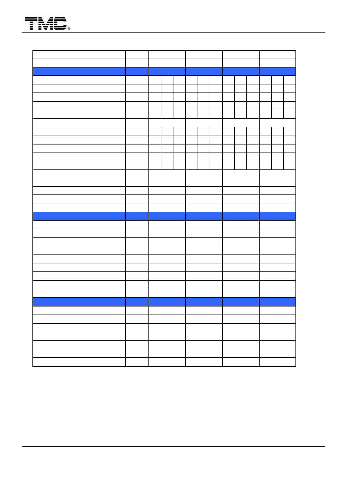
1 Machine Specifications
Machine Model Number TMC 30E TMC 60E TMC 90E TMC 120E
International Size Code 300/104 600/140 900/230 1200/380
A. Injection Unit Code 104 140 230 380
1. Screw size A B C A B C A B C A B C
2. Screw diameter mm 20 22 25 25 30 32 32 35 40 35 40 45
3. Screw length to diameter ratio L/D 22 20 20 24 20 18.75 21.9 20 17.5 22.9 20 17.8
4. Injection pressure @ 140bar bar x x x 23301618 1422 191516001225219416801327
5. Injection pressure @ 170bar bar 251920401686 28291964 1727 232419431488 266420401612
6. Injection stroke mm 100 120 150 180
7. Calculated injection volume cm3 31 38 49 59 85 97 121 144 188 173 226 286
8. Injection capacity - PS gm 29 35 45 54 78 89 111 133 173 159 208 263
9. Plasticizing rate LS/HT kg/hr x x x 17 26 30 32 45 59 41 53 76
HS/LT kg/hr 15 19 27 21 32 36 39 54 71 57 74 106
10. Injection rate @ 70kg/cm2 cm3/sec 59 71 92 55 79 90 88 105 137 97 127 161
11. Screw speed / torque LS/HT rpm/Nm 220/550 240/640 217/950
HS/LT rpm/Nm 350/310 275/450 288/550 303/670
12. Nozzle force kN 35 60 60 60
13. Heating input power kW 4.0 5.5 6.3 8.2
14. Barrel heating zones no. 3+2 3+2 3+2 3+2
B. Clamping Unit Code 300 600 900 1200
1. Clamping force kN 300 600 900 1200
2. Mold opening stroke mm 230 270 300 350
3. Open daylight mm 550 590 660 775
4. Die-height available (Std.) mm 120-320 100-320 150-360 150-425
5. Size of platens H x V mm 460*420 500*500 590*590 640*640
6. Space between tie-bars mm 320*280 320*320 400*400 425*425
7. Tie-bar diameter mm 45 55 65 75
8. Ejector force kN 17 44 44 44
9. Ejector stroke mm 60 80 80 100
C. General
1. Pump motor power kW (hp) 11.25 (15) 11.25 (15) 15 (20) 18.75 (25)
2. Hydraulic system pressure bar 170 140 or 170 140 or 170 140 or 170
3. Total installed power kW 15.25 16.7 21.3 27
4. Oil tank capacity liter 100 260 260 300
5. Hopper capacity kg 12 36 36 36
6. Total machine weight (approx.) kg 2500 3100 3800 5200
7. Machine dimensions LxWxH m 3.25*1.10*1.45 3.90*1.15*1.85 4.10*1.25*1.904.40*1.30*1.95
InjectionMoldingMachine Chapter2
2-2 V3.0
Machine Model Number TMC 150E TMC 200E TMC 250E TMC 350E
International Size Code 1500/640 2000/960 2500/1500 3500/2700
A. Injection Unit Code 640 960 1500 2700
1. Screw size ABCABCABCABC
2. Screw diameter mm 40 45 50 50 55 60 55 60 65 70 75 80
3. Screw length to diameter ratio L/D 22.5 20 18 22 20 18.3 21.8 20 18.5 21.4 20 18.8
4. Injection pressure @ 140bar bar 208316451333 195216131355 203617111458 196417111504
5. Injection pressure @ 170bar bar 252919981618 237019591646 247320781770 238520781826
6. Injection stroke mm 180 250 300 350
7. Calculated injection volume cm3 226 286 353 491 594 707 713 848 995 134715461759
8. Injection capacity - PS gm 208 263 325 452 546 650 656 780 916 123914231619
9. Plasticizing rate LS/HT kg/hr 57 81 107 94 128 159 132 164 210 198 227 242
HS/LT kg/hr 67 94 125 126 170 211 165 205 263 247 283 302
10. Injection rate @ 70kg/cm2 cm3/sec 128 162 200 196 237 283 242 288 338 292 336 382
11. Screw speed / torque LS/HT rpm/Nm 233/1090 205/1760 212/2280 164/3640
HS/LT rpm/Nm 271/950 273/1330 265/1760 205/2650
12. Nozzle force kN 60 60 60 96
13. Heating input power kW 9.3 15 19.2 32
14. Barrel heating zones no. 3+2 3+2 3+2 4+2
B. Clamping Unit Code 1500 2000 2500 3500
15. Clamping force kN 1500 2000 2500 3500
16. Mold opening stroke mm 380 430 510 640
17. Open daylight mm 880 980 1110 1390
18. Die-height available mm 150-500 200-550 200-600 300-750
19. Size of platens H x V mm 670*670 760*760 850*850 1050*1050
20. Space between tie-bars mm 450*450 510*510 560*560 710*710
21. Tie-bar diameter mm 80 90 100 120
22. Ejector force kN 44 70 70 90
23. Ejector stroke mm 100 120 140 180
C. General
24. Pump motor power kW (hp) 22.5 (30) 30 (40) 37.5 (50) 45 (60)
25. Hydraulic system pressure bar 140 or 170 140 or 170 140 or 170 140 or 170
26. Total installed power kW 31.8 45 56.7 77
27. Oil tank capacity liter 310 500 600 800
28. Hopper capacity kg 36 68 68 90
29. Total machine weight (approx.) kg 5800 8000 10000 16000
30. Machine dimensions LxWxH m 4.60*1.35*2.005.50*1.40*2.205.85*1.50*2.257.40*1.80*2.40

InjectionMoldingMachine Chapter2
2-3 V3.0
Machine Model Number TMC 500E TMC 750E TMC 1000E
International Size Code 7500/5700 7500/5700 10000/9200
A. Injection Unit Code 5700 5700 9200
1. Screw size AABAB A B B C
2. Screw diameter mm 80 85 95 95 100 110 110 120 130
3. Screw length to diameter ratio L/D 21.3 20 17.9 21.1 20 18.2 21.8 20 18.5
4. Injection pressure @ 140bar bar 199817701417 1787 1613 1333 1862 1565 1333
5. Injection pressure @ 170bar bar 242621491721 2170 1958 1619 2261 1900 1619
6. Injection stroke mm 450 450 520
7. Calculated injection volume cm3 201122702835 3190 3534 4276 4942 5881 6902
8. Injection capacity - PS gm 185020882608 2935 3252 3934 4546 5411 6350
9. Plasticizing rate LS/HT kg/hr 147 200 277 305 320 409 508 611 680
HS/LT kg/hr 211 286 397 438 461 587 642 765 812
10. Injection rate @ 70kg/cm2 cm3/sec 352 397 496 517 573 693 779 927 1088
11. Screw speed / torque LS/HT rpm/Nm 100/6650 111/8060 138/9580
HS/LT rpm/Nm 143/4550 158/5600 173/8060
12. Nozzle force kN 96 125 125
13. Heating input power kW 41 50 82
14. Barrel heating zones no. 4+2 4+2 4+2
B. Clamping Unit Code 5000 7500 10000
15. Clamping force kN 5000 7500 10000
16. Mold opening stroke mm 820 1000 1150
17. Open daylight mm 1720 2000 2350
18. Die-height available mm 350-900 400-1000 600-1200
19. Size of platens H x V mm 1250*1250 1500*1500 1700*1700
20. Space between tie-bars mm 850*850 1000*1000 1150*1150
21. Tie-bar diameter mm 150 180 200
22. Ejector force kN 110 170 215
23. Ejector stroke mm 200 240 300
C. General
24. Pump motor power kW (hp) 56 (75) 75 (100) 112 (150)
25. Hydraulic system pressure bar 140 or 170 140 or 170 140 or 170
26. Total installed power kW 97 125 194
27. Oil tank capacity liter 1000 1400 1600
28. Hopper capacity kg 90 120 120
29. Total machine weight (approx.) kg 25000 40000 60000
30. Machine dimensions LxWxH m 8.70*2.00*2.5510.70*2.15*2.8512.00*2.45*3.05
InjectionMoldingMachine Chapter2
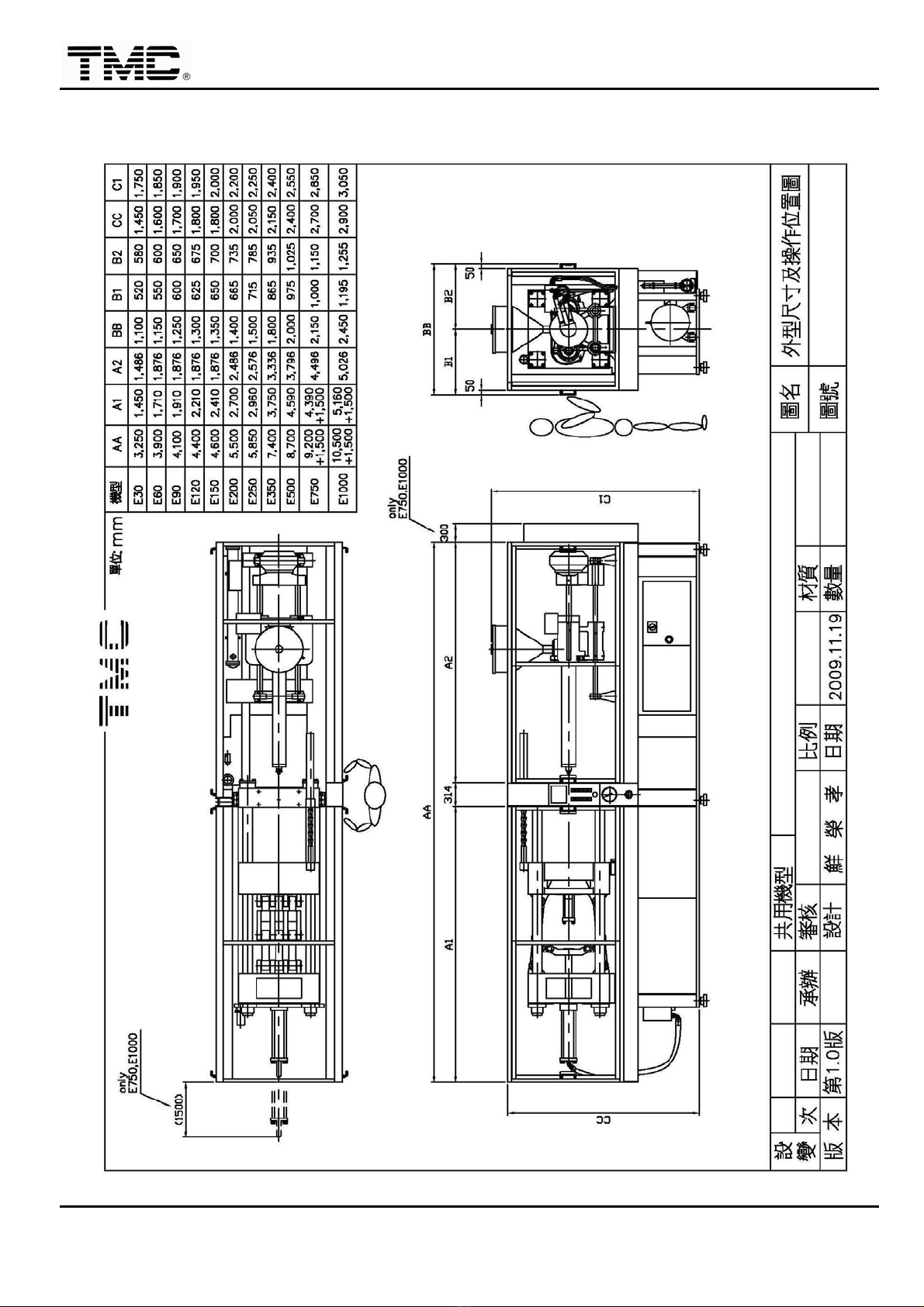
2-4 V3.0
2 Machine dimensions
This manual suits for next models
10
Table of contents
Popular Industrial Equipment manuals by other brands


MUEGGE
MUEGGE Magnetron Head MH3000S-211CV operating instructions

Siemens
Siemens BD2-AK04/SNH Series installation instructions

Balluff
Balluff BTL7-S5 B-M Series Condensed guide

KAKA Industrial
KAKA Industrial TR-40 Operation manual

Siemens
Siemens KFV operating instructions

Sagola
Sagola 6110 Instruction manual / spare parts list


