TMG TMG-PS72 User manual


WWW.TMGINDUSTRIAL.COM P1/28 Toll Free:1-877-761-2819
TABLE OF CONTENTS
GENERAL COMMENTS.................................................................. 2
SAFETY PRECAUTIONS ............................................................... 2
SAFETY DECALS............................................................................ 5
MAIN SPECIFICATIONS.................................................................. 6
SKID STEER REQUIREMENTS ...................................................... 7
IDENTIFICATIONS OF MAIN COMPONENTS................................. 9
OPERATING INSTRUCTIONS ....................................................... 10
Attaching
Check before operation
Operation
Dumping
Disconnecting
Transporting
Storage
MAINTENANCE ........................................................................... 20
LONG TERM STORAGE................................................................. 20
PARTS CHART ............................................................................... 21

WWW.TMGINDUSTRIAL.COM P2/28 Toll Free:1-877-761-2819
GENERAL COMMENTS
Congratulations on the purchase of a new Sweeper. This product has been designed
and built to clean and handle all types of material including fine dirt, gravel, mud,
millings and other debris. You or any other person who will be assembling,
operating, maintaining, or working with this product are required to read and
completely understand the information and instructions contained in this manual. If
any questions about it, please obtain further assistance by contacting the dealer
from which this product was purchased.
Your attachment was carefully designed and manufactured to give you many years
of dependable service. Only minor maintenance (such as cleaning and lubricating) is
required to keep it in top working condition. Be sure to observe all maintenance
procedures and safety precautions in this manual, on the safety decals located on
the attachment, and on any equipment on which the attachment is mounted.
The purpose of this manual is to assist in assembling, mounting, operating, and
maintaining your Hydraulic Sweeper. It can help you to do a better, safer job. The
manual covers models of 72"/560 and 72"/670. The difference between the models
is the dimensions of the broom and hydraulic flow capacity of the product
Read this manual carefully, and become familiar with the operating procedures
before attempting to operate your attachment.
The illustrations and data used in this manual were current at the time of printing,
but due to possible engineering and/or production changes, this product may vary
slightly in detail. Our company reserves the right to redesign and/or change
components as may be necessary without notification to anyone.
REMEMBER: never let anyone operate this attachment without them having
read and completely understand the “Safety ” and “Operating Instructions”
sections of this manual, or having them be fully trained by an experienced,
qualified person who has read and completely understands the “Safety
Precautions” and Operating Instructions”.

WWW.TMGINDUSTRIAL.COM P3/28 Toll Free:1-877-761-2819
SAFETYPRECAUTIONS
THE USE OF THIS EQUIPMENT IS SUBJECT TO CERTAIN HAZARDS
WHICH CANNOT BE PROTECTED AGAINST MECHANICAL MEANS OR
PRODUCT DESIGN. ALL OPERATORS OF THIS EQUIPMENT MUST READ
AND UNDERSTAND THIS ENTIRE MANUAL, PAYING PARTICULAR
ATTENTION TO SAFETY AND OPERATING INSTRUCTIONS, PRIOR TO
USING THE HYDRAULIC ATTACHMENT. IF THERE IS SOMETHING IN
THIS MANUAL YOU DO NOT UNDERSTAND, ASK YOUR SUPERVISOR TO
EXPLAIN IT TO YOU. FAILURE TO OBSERVE THESE SAFETY
PRECAUTIONS CAN RESULT IN DEATH OR SERIOUS INJURY OR SERIOUS
EQUIPMENT DAMAGE.
All bystanders should be kept a minimum of 10 feet (3 meters) away from
working area of the attachment.
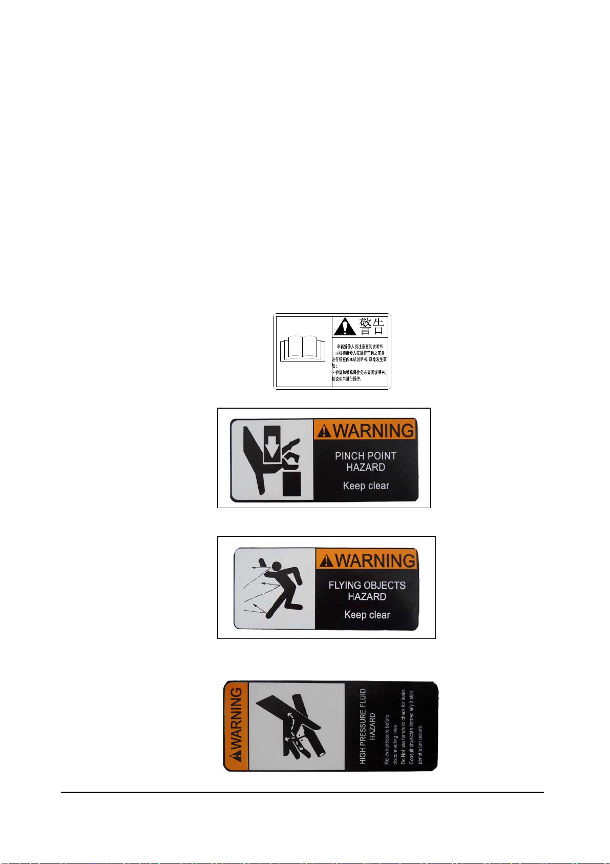
PROTECT AGAINST FLYING DEBRIS: Always wear an OSHA approved hard
hat and safety eye protection when operating or servicing this equipment. Do not
wear loose fitting clothing, flopping cuffs, dangling neckties and scarves, or rings and
wrist watches that can catch moving parts.
An operator must not use drugs or alcohol which can change his alertness or
coordination. An operator taking prescription or over-the-counter drugs should seek
medical advise on whether or not he can safely operate equipment.
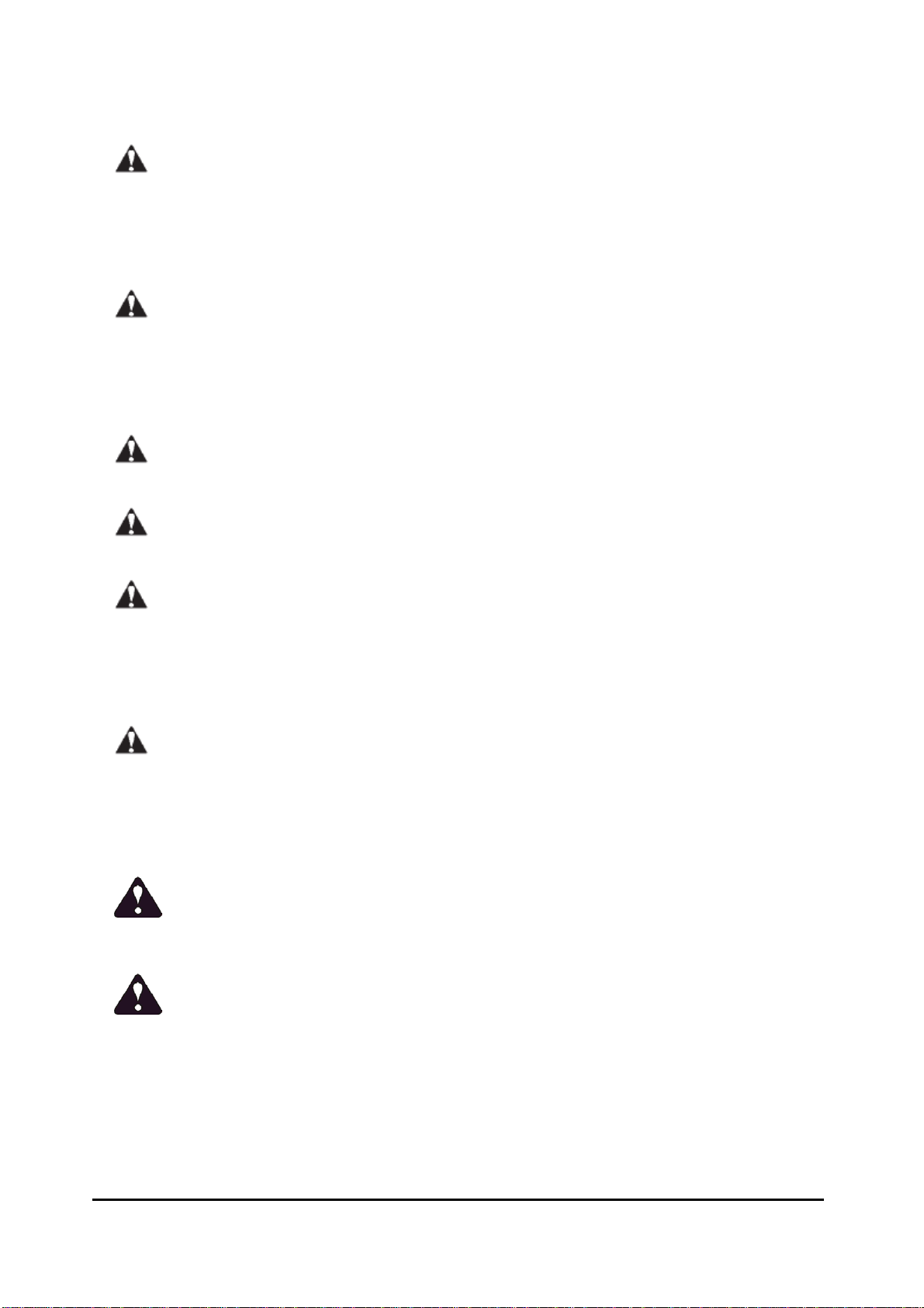
Never alter or remove any safety decals or shields. Replace all missing or
damaged safety decals or safety shields. Check this manual for location of these
items and replace immediately if damaged or illegible.
Never adjust a relief valve for pressure higher than recommended by vehicle
manufacturer.
Whenever changing or installing this or other attachments, make sure all
connections are securely fastened. Travel only with the attachment in a safe transport
position to prevent uncontrolled movement. Drive slowly over rough ground and on
slopes. Remove attachment from vehicle when transporting to and from job site.
LOWER OR SUPPORT RAISED EQUIPMENT: Before exiting vehicle, lower
attachment to ground, turn off vehicle engine and lock vehicle brakes. Do not work
under raised booms without supporting them. Do not use support material made of
concrete blocks, logs, buckets, barrels or any other material that could suddenly
collapse or shift positions. Make sure support material is solid, not decayed, warped,
twisted, or tapered. Lower booms to ground level or onto blocks. Lower booms and

WWW.TMGINDUSTRIAL.COM P4/28 Toll Free:1-877-761-2819
attachments to the ground before leaving the cab or operator’s station.
Never check a pressurized system for leaks with your bare hand. Oil escaping
from pinhole leaks under pressure can penetrate skin and could cause serious
infection. Hold a piece of cardboard up next to suspected leaks and wear a face
shield or safety eye protection. If any fluid is injected into the skin, it must be removed
immediately by a doctor familiar with this type of injury.
Before disconnecting hydraulic lines or fittings, be sure to relieve all pressure by
cycling all hydraulic controls after shutdown. Remember hydraulic systems are under
pressure whenever the engine is running and may hold pressure after shutdown.
Before applying pressure to the system make sure all connection are tight and that
there is no damage to lines, fittings and hoses.
Flow and pressure gauges, fittings and hoses must have a continuous operating
pressure rating of at least 25% higher than highest pressures of the system.
Avoid steep hillside operation which could cause the vehicle to overturn. Consult
your vehicle operator’s and safety manuals for maximum incline allowable.
Never perform any work on an attachment unless you are authorized and
qualified to do so. Always read the operator service manual(s) before any repair is
made. After completing maintenance or repair, check for correct functioning of the
attachment. If not functioning properly always tag “DO NOT OPERATE” until all
problems are corrected.
This manual covers the safe use, installation, operation and service instructions
for the attachment only. Always read the operating and safety manuals prepared for
your vehicle and any other attachments before using them.
EQUIPMENT SAFETY PRECAUTIONS
CAUTION!Avoid pinch points and be aware of rotating parts when operating the
attachments.
WARNING! ROTATING OBJECTS!
•Check your work area, for objects that could harm the operator or others if
thrown by the attachment. Remove these items before working.
• Do not carry load with arms in the raised position. Always carry loads close to
the ground. Do not step off platform with load raised.
• Use extra care when loading or unloading the machine onto a trailer or truck.

WWW.TMGINDUSTRIAL.COM P5/28 Toll Free:1-877-761-2819
• Slow down before turning. Sharp turns on any terrain may cause loss of control.
• Always lower the loader arms to the ground, shut off the engine and remove the
key before getting off the unit.
• Turn off engine before performing maintenance. If lift arms must be left raised for
maintenance or any other reason, use a positive lift arm lock to secure the arms in
place. Serious damage or personal injury could result from lift arms accidentally
lowering. SAFETY DECALS
1、WARNING
READANDUNDERSTANDOPERATINGINSTRUCTIONSANDSAFETYINFORMATIONPRIORTO
OPERATINGYOURATTACHMENT.。
2、PINCHPOINTHAZARD
3、FLYINGOBJECTSHAZARD
4、HIGHPRESSUREFLUIDHAZARD

WWW.TMGINDUSTRIAL.COM P6/28 Toll Free:1-877-761-2819
MAIN SPECIFICATIONS:
SPECIFICATIONS AND DESIGN ARE SUBJECT TO CHANGE WITHOUT NOTICE AND WITHOUT
LIABILITY THEREFOR.
NOTE: The illustrations and data used in this manual were current (according to the information
available to us) at the time of printing, however, we reserve the right to redesign and change the
brooms as may be necessary without notification.
SPECIFICATIONS Standard PICK-UP Standard PICK-UP
Model Number TMG-PS72 72"/670
Working Width 1828 mm (72") 1828 mm (72").
Overall Width 2200 mm 2200 mm
Brush Diameter 22" (560mm) 26"(670mm)
Heaped Capacity 14.3 cu.ft (0.4 m³)14.3 cu.ft (0.4 m³)
Cutting Edge on bucket Bolt on, and replaceable full
length cutting edge
Bolt on, and replaceable full length
cutting edge
Number of Motors 1 1
Maximum Articulation 30° 30°
Hydraulic Flow Rate 42-95 L/min (12-25GPM) 45-95 L/min (12-25GPM)
Oil Pressure Range 16-21 MPa 16-21 MPa
Overall dimension L*W*H 1350*2200*630 mm 1560*2200*700 mm
Weight (approximate) 440 kg 585 kg

WWW.TMGINDUSTRIAL.COM P7/28 Toll Free:1-877-761-2819
SKID STEER LOADER REQUIREMENTS
TheSweeperisdesignedtoattachtoskidsteerswiththefollowingminimumrequirements:
SAE Lift Capacity . . . . . . . . . . . . . . .. . . . . . . . . . . . . . . . . . 1200 lbs.
Hitch Type . . . . . . . . . . . . . . . . . . . . . . Universal Quick Attach Hitch
Hydraulic Pressure Rating . . . . . . . . . . . . . . . . . . . . 1600 - 2200 PSI.
Motors & Hoses . . . . . . . . . . . . . . . . . . . . . . . . . . . . . . . 10 - 23 GPM.
Hydraulic Hoses . . . . . . . . . . . . . . 3 - Hydraulic couplings: Inlet/Outlet/Case drain line
Connection:withFlat‐FacedCouplers:
1/2” Flat-face Quick Coupling (male) & 1/2” Flat-face Quick Coupling
(female)
3/8” Flat-face Quick Coupling (female);(for case drain line if equipped on
skid steer loader)
Caution:
DO NOT EXCEED 23 GALLONS PER MINUTE!!
Severe injury or death could occur due to the increased RPM.
CAUTION: NEVER store angle broom with weight on bristles. This will cause warping
of bristles. ALWAYS store on stands keeping broom bristles off the ground.
DANGER!ROTATING PARTS HAZARD! STAY BACK!
OBJECTSCANBE THROWN!
DO NOT operate near bystanders.
IMPORTANT:Theattachmentshavebeenequippedwith3hoses.Hosefittingsandquick
couplerstotheskidsteerloaderareoptional.Ifnotpurchasedwithit,theycanbe
purchasedfromyourdealerorlocalmarket.Makesurethecouplerscompatibletoattach
theunittotheskid‐steerauxiliaryhydrauliccouplers,includingthetype,thedimensionsand
thequantities.
NOTE! DEALERS AND/OR OWNERS MUST DETERMINE THAT COMPATIBILITY
BETWEEN THE SKID STEER LOADER AND ATTACHMENT EXISTS.
Compatibility includes, but is not limited to items such as operator clearance,
hitch (mounting assembly) component strength, and hydraulics.
The 3rd hose and quick coupler for case drain line is only an option. Itis only used for
attaching to the skid steer loader equipped with Case drain line along its path to the
sump/tank. If not equipped, then just remove the hose of the attachment.

WWW.TMGINDUSTRIAL.COM P8/28 Toll Free:1-877-761-2819
The sweeper was supplied with hoses. Proper hose end fittings and/or quick couplers must
be purchased as the hose threads.
Hose End Fittings:............................ One hose end must be metric M18X1.5. The fitting for the
other end can be whatever you determine to be the most beneficial to making the connection to your
skid steer.

WWW.TMGINDUSTRIAL.COM P9/28 Toll Free:1-877-761-2819
IDENTIFICATIONS OF MAIN COMPONENTS

WWW.TMGINDUSTRIAL.COM P10/28 Toll Free:1-877-761-2819

WWW.TMGINDUSTRIAL.COM P11/28 Toll Free:1-877-761-2819
OPERATION INSTRUCTIONS:
*INSTALLATION INSTRUCTIONS
The installation of your ATTACHMENT is the same for any other powered
attachment for your skid steer loader:
NOTE:
1. Remove any attachments from the front of the loader.
2. Following all standard safety practices and the instructions for installing
an attachment in your skid-steer operator's manual, install the
ATTACHMENT onto your skid-steer.
NOTE: It is important to make sure the locking mechanism on your quick
attach is engaged, therefore locking the attachment onto the skid-steer.
DANGER
ACrushingHazardexistswhenhooking‐upequipment.Donotallowanyonetostandbetweenskid
steerloaderandimplementwhilehooking‐uptoimplement.Donotoperatehydraulicswhile
someoneisneartheskidsteerloaderorimplement.
CAUTION
MakesureyourskidsteerloaderhitchisproperlyattachedtotheSweeperhitch.Itmustbesecured
undertheSweepertopanglebarsandloaderhitchplatelockhandlesmustbelockeddownwith
lockingpinsextendingfullythroughbottomslotsintheSweeperhitch.Animproperlyattached
Sweepercancomelooseandfall.
WARNING
Nevergounderneathequipment(loweredtothegroundorraised)unlessitisproperlyblockedand
secured.Neverplaceanypartofthebodyunderneathequipmentorbetweenmoveablepartseven
whentheenginehasbeenturnedoff.Hydraulicsystemleakdown,hydraulicsystemfailures,
mechanicalfailures,ormovementofcontrolleverscancauseequipmenttodroporrotate
unexpectedlyandcausesevereinjury.

WWW.TMGINDUSTRIAL.COM P12/28 Toll Free:1-877-761-2819
*ATTACHING TO SKID STEER LOADER:
1. Check for and remove any debris in the hitch point areas before attaching to Sweeper to
skid steer loader.
Read the skid steer operator's manual connecting and removing instructions.
Position hydraulic hoses so they will not be pinched when connecting the sweeper.
The skid steer lock handles should be in the unlocked position and the lock pins retracted.
2. Drive skid steer loader slowly to the Sweeper and carefully align the skid steer to the
sweeper, making sure hitch plate on the skid steer loader is parallel with the Sweeper’s top
angle bars.
3. Rotate top of skid steer loader tilt arms slightly forward.
4. Position top of skid steer loader hitch plate under the top angled bars and slowly raise
loader hitch plate up until hitch plate is seated under the top angle bars (attachment flange).
Lower skid steer lift arms to their lowest position.
LOCKHANDLES.REFER
TOTHEMANUALOF
SKIDSTEERLOADER.
LOCKPINOFSKID
STEERS
MOUTINGHITCHPLATE

WWW.TMGINDUSTRIAL.COM P13/28 Toll Free:1-877-761-2819
5. Rotate top of skid steer loader tilt arms back until Sweeper makes full contact with face of
hitch plate so the lock handles can be engaged.
6. Push lock handles on the skid steer loader hitch down. Make sure lock pins go through
bottom slots in the Sweeper hitch and handles are fully locked down.
The lock pins must be completely extended and secured into the slots provided on the
sweeper.

WWW.TMGINDUSTRIAL.COM P14/28 Toll Free:1-877-761-2819
Hydraulic Hose Hook-up
Connect hydraulic hoses to skid steer auxiliary quick couplers.
2 or 3 quick couplers should be connected according to the equipment on the skid steer loader. If only
2 couplers are equipped on the skid steer without the case drain line, then just remove the 3rd one and
plug the outlet port accordingly.
DANGER
Hydraulicfluidunderhighpressurecanpenetrateskin.Wearprotectiveglovesandsafetyglassesor
goggleswhenworkingwithhydraulicsystems.Useapieceofcardboardorwoodratherthanhands
whensearchingforhydraulicleaks.Ifhydraulicfluidisinjectedintotheskinoreyes,itmustbe
treatedbyadoctorfamiliarwiththistypeofinjurywithinafewhoursorgangrenemayresult.DO
NOTDELAY.
IMPORTANT: Collect and dispose all oil spills and leaks in an environmentally safe manner.
IMPORTANT: Hose routing is the responsibility of the owner/operator of the Sweeper.
Pinched and/or stretched hoses are not covered under the warranty.ection 2: Eq
IMPORTANT: Make sure all coupler fittings are clean before connecting them together.
Two high pressure hydraulic outlets are required for the hydraulic motor.
1. Route hydraulic hoses along the most convenient path to access your skid steer loader.
2. Clean quick connect couplers of dirt and then connect couplers to the skid steer couplers.
Make sure quick connect couplers have fully engaged.
If they have not, check the following:
a. Make sure couplers are same size and type.
b. Make sure hydraulic pressure has been released.
CONNECTQUICK
COUPLERS
REFERTOTHEMANUAL
OFSKIDSTEERLOADER

WWW.TMGINDUSTRIAL.COM P15/28 Toll Free:1-877-761-2819
NOTE:
The ATTACHMENT attaches to the toolbar/quick-attach mechanism of your
skid-steer loader. Due to this arrangement, thorough knowledge of the skid-steer
controls is necessary for machine operation. Read and understand your skid steer
operator's manual for information regarding skid-steer operation before attempting to
use the ATTACHMENT.
Follow all installation instructions for the proper installation of the unit onto your
skid-steer before attempting to operate your ATTACHMENT.
Nowthemechanismandhydraulicdevicehavebeen
properlyconnectedtobereadyforworking.

WWW.TMGINDUSTRIAL.COM P16/28 Toll Free:1-877-761-2819
Check Equipment before operation
It is important to check clearance before putting the Sweeper into operation. Make sure
hydraulic hoses are long enough and won’t become pinched or entangled in the equipment.
1. Visually inspect hydraulic hoses for possible pinch points and shortness. If needed, make
hose adjustments before putting equipment into service.
2. Start skid steer/tractor and raise loader arms high enough to tilt the hitch plate fully down
without Sweeper making contact with the ground.
3. Fully extend and retract hydraulic cylinders on the end of the skid steer loader arms while
watching for interferences between skid steer loader and Sweeper frame.
4. Raise skid steer/ loader arms fully up and repeat steps above.
IMPORTANT: Make sure hydraulic hoses are long enough and properly secured so that they
do not become stretched or pinched through their full range of motions.
NOTICE:
■ Maximum oil flow is 25 gpm (94.8 liters/min) at 3000 psi (206.8 bars). See the skid
steer manual for oil flow specifications.
Before Each Use
Run the sweeper with the skid steer at a slow idle. Check for hydraulic leaks or other
problems and make corrections, if necessary, before using the sweeper
During Use
Carry the sweeper low to the ground so that the operator has good visibility and stability. Avoid any
sudden movements. Avoid excessive downward pressure on the brush sections to prevent excessive
wear. A two to four inch wide pattern for the broom is sufficient for most applications. Ensure that the
adjustment bolts are equally adjusted in order to prevent an uneven wear pattern.
5. Rotate top of skid steer loader tilt arms back until Sweeper makes full contact with face of
hitch plate so the lock handles can be engaged.
6. Push lock handles on the skid steer loader hitch down. Make sure lock pins go through
bottom slots in the Sweeper hitch and handles are fully locked down.
The lock pins must be completely extended and secured into the slots provided on the
sweeper.

WWW.TMGINDUSTRIAL.COM P17/28 Toll Free:1-877-761-2819
Check Equipment before operation
It is important to check clearance before putting the Sweeper into operation. Make sure
hydraulic hoses are long enough and won’t become pinched or entangled in the equipment.
1. Visually inspect hydraulic hoses for possible pinch points and shortness. If needed, make
hose adjustments before putting equipment into service.
2. Start skid steer/tractor and raise loader arms high enough to tilt the hitch plate fully down
without Sweeper making contact with the ground.
3. Fully extend and retract hydraulic cylinders on the end of the skid steer loader arms while
watching for interferences between skid steer loader and Sweeper frame.
4. Raise skid steer/ loader arms fully up and repeat steps above.
IMPORTANT: Make sure hydraulic hoses are long enough and properly secured so that they
do not become stretched or pinched through their full range of motions.
NOTICE:
■ Maximum oil flow is 25 gpm (94.8 liters/min) at 3000 psi (206.8 bars). See the skid
steer manual for oil flow specifications.
Before Each Use
Run the sweeper with the skid steer at a slow idle. Check for hydraulic leaks or other
problems and make corrections, if necessary, before using the sweeper
During Use
Carry the sweeper low to the ground so that the operator has good visibility and
stability. Avoid any sudden movements. Avoid excessive downward pressure on the
brush sections to prevent excessive wear. A two to four inch wide pattern for the
broom is sufficient for most applications. Ensure that the adjustment bolts are equally
adjusted in order to prevent an uneven wear pattern.

WWW.TMGINDUSTRIAL.COM P18/28 Toll Free:1-877-761-2819
Operation of sweeping
The sweeper is capable of, and in fact intended to be utilized for, sweeping away dirt, light
snow and other debris. Directions for use are as follows:
1. Start the skid steer at idle speed and raise the brush head.
2. Use low engine speeds to save wear and tear on the sweeper and to prevent dust from
billowing up during sweeping.
NOTE: Do not engage the brush at high engine speeds. This damages the sweeper and
motor.
3. Engage the brush head and lower it to the ground.
4. Gradually increase skid steer engine rpm to sweeping speed.
Travel forward at 5 mph or less.
NOTICE
■Shifting brush rotation from forward to reverse while the brush is rotating damages
the sweeper and motor.
5. When sweeping forward, rotate the brush so debris goes over the brush and into the
bucket.
6. When sweeping in reverse, rotate the brush so debris is pushed into the bucket, similar to
sweeping into a dustpan.
7. If necessary, install or replace plastic ties in flap holes to hold the front and sides together.
SLOW DOWN!!
Directing Debris
Observe wind direction. Sweeping with the wind makes sweeping more effective and helps

WWW.TMGINDUSTRIAL.COM P19/28 Toll Free:1-877-761-2819
keep debris off the operator.
Dirt and Gravel
To keep dust at a minimum, plan your sweeping for days when it is overcast and humid, or
after it has rained. Also, sweep so the wind blows at your back or in the direction the brush
head is angled.
Low brush speeds and moderate ground speeds work best for cleaning debris from hard
surfaces. Brush speeds that are too fast tend to raise dust because of the aggressive
sweeper action.
To sweep gravel, use just enough brush speed to roll gravel, not throw it.
Heavy Debris
For two inches or more of heavy debris, medium/high and ground speeds of less than five
mph are recommended. Sweep path less than the full width of the broom. Increase engine
speed if debris becomes very heavy.
Transporting
Always follow safety rules, carry low to ground and travel slowly.
Only raise a load when dumping.
Dumping Loads
Transport to dumping location before raising. Only dump load while on a firm level surface.
Slowly raise load to required dumping height. Rotate pick-up broom forward to empty the bucket.
Dump Position
Table of contents
Popular Blower manuals by other brands

Greenlee
Greenlee Li'l Fisher 390 instruction manual

BE Ag & Industrial
BE Ag & Industrial BE-LBR55 Operations & parts manual

Hawksmoor
Hawksmoor TOOLSTATION 18783 ORIGINAL USER INSTRUCTIONS

Giant-Vac
Giant-Vac 2551E Operator's manual

Toyama
Toyama TB26-GII owner's manual

Makita
Makita AS001G instruction manual