TMG TMG-PJ55 User manual

5500-lb Hydraulic Pallet Jack
Model:TMG-PJ55
WWW.TMGINDUSTRIAL.COM Toll Free:1-877-761-2819
PRODUCT MANUAL
Please read the product manual completely before assembly
Check against the parts list to make sure all parts are received
Wear proper safety goggles or other protective gears while in assembly
Missing parts or questions on assembly?
Do not return the product to dealer, they are not equipped to handle your
requests
V2021.05.13

ATTENTION:
1. The waste packages should be sorted and put into solid dustbins according to the
materials and be collected disposal by local special environment protection bureau.
To avoid pollution, it’s forbidden to throw away the wastes randomly.
2. To avoid leaking during the use of the products, the user should prepare some
absorbable materials (scraps of wooden or dry duster cloth) to absorb the leaking oil
in time. To avoid second pollution to the environment, the used absorbable materials
should be handed in to special departments in terms of local authorities.
WWW.TMGINDUSTRIAL.COM P2/14 Toll Free:1-877-761-2819

Thank you for using our pallet trucks. Your pallet truck is made of high quality steel and
is designed for the horizontal lifting and transport of loads on a pallet or standardized
containers on a level, fixed base. For your safety and correct operation, please carefully
read this instruction before using it.
NOTE: All of the information reported herein is based on data available at the
moment of printing. We reserves the right to modify our own products at any
moment without notice and liability in any sanctions. So, it is suggested to always
verify possible updates and changes.
1. GENERAL SPECIFICATIONS
Capacity (lb)
5500
Maximum. Fork Height
(mm)
195
Minimum. Fork Height
(mm)
85
Fork Length (mm)
1220
Width Overall Forks (mm)
685
Individual Fork Width (mm)
160
Load Wheel Diameter (mm)
Ø 80x70(or Ø 74x70) Nylon, Polyurethane
Steering Wheel Diameter (mm)
Ø 200(or Ø 180) Nylon, Polyurethane, Rubber
Materials and specifications are subject to change without notice.
2. ATTACHING DRAW-BAR TO PUMP UNIT
If you have purchased a wooden box of pallet truck, some assembly is required.
Certainly, you need some tools, a hammer, a pliers, a spanner, etc; and some parts, one
axle with hole (105), two elastic pins (106)(Note one is in the axle (105)), these parts
are putted in a plastic bag, which is putted into the draw-bar.
NOTE: The number of draw-bar and pump should be the same.
WWW.TMGINDUSTRIAL.COM P3/14 Toll Free:1-877-761-2819

Fig. 1
1. Draw-bar 2. Pin 3. Axle with hole 4. Elastic pin 5. Fork frame
When attaching the handle, you had better squat just behind the pallet truck. Then you:
2.1 Insert the draw-bar onto the pump piston (303),then use a hammer to insert the axle
with hole (105) into the hydraulic pump and draw-bar from the right to left. (See fig. 2 ).
2.2 Let control handle(117 or 120G) to the ‘LOWER’
position, then pass the adjusting nut(104), adjusting
bolt(103) and chain(102) through the hole of axle(105)
with your hand (See fig. 3).
Fig. 2
WWW.TMGINDUSTRIAL.COM P4/14 Toll Free:1-877-761-2819

Fig. 3
2.3 Press the draw-bar (110, 110B or 111G) down, take away the pin(#2) (See Fig. 1).
2.4 Let the control handle (117 or 120G) on ‘RAISE’ position, then raise the lever plate
(319) with the pin (#2) and insert the adjusting bolt(103) into the front slot of lever
plate (319), note to keep the adjusting nut (104) on the under side of the lever plate.
2.5 Use a hammer to tap another elastic pin (106) into the axle with hole (105).
The draw-bar is now assembled to the pump.
3. ADJUSTING RELEASE DEVICE
On the draw-bar of this pallet truck, you can find the control handle(117 or 120G) which
can be adjusted in three positions :
Raise -handle down
Drive -handle in center position
Lower -handle up, the lever moves back the drive position when released.
WWW.TMGINDUSTRIAL.COM P5/14 Toll Free:1-877-761-2819

If however they have been changed, you can adjust according to following step:
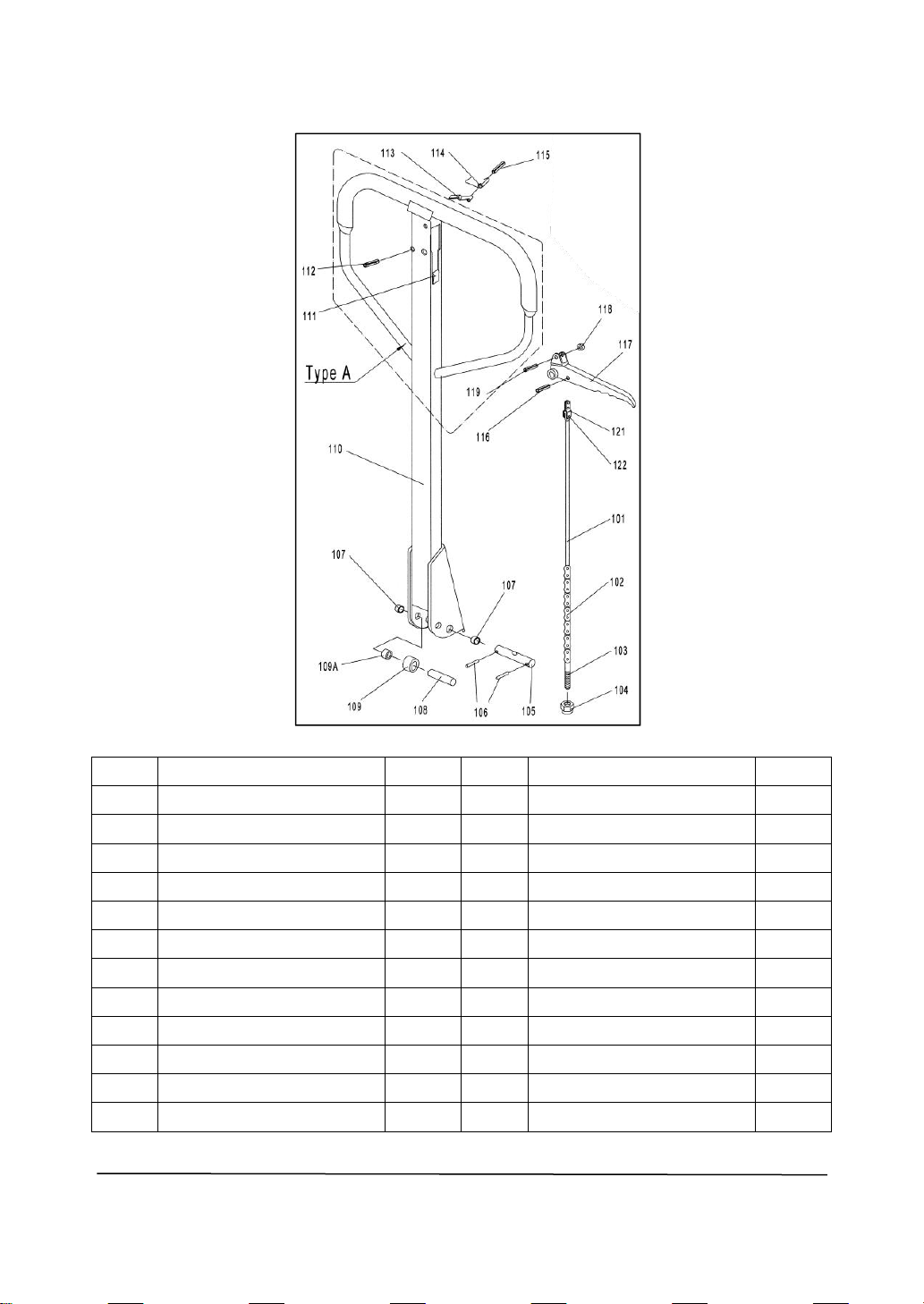
3.1 If the forks elevate while pumping in the DRIVE position, turn the adjusting nut (104)
on the adjusting bolt(103) or screw(318) clockwise until pumping action does not
raise the forks and the DRIVE position functions properly.
3.2 If the forks descend while pumping in the DRIVE position, turn the nut(104) or
screw(318) counter-clockwise until the forks do not lower.
3.3 If the forks do not descent when the control handle (117 or 120G) is in the LOWER
position, turn the nut(104) or screw (318) clockwise until raising the control
handle(117 or 120G) lowers the forks. Then check the DRIVE position according to
item 3.1 and 3.2 to be sure the nut (104) and screw(318) is in the proper position.
3.4 If the forks do not elevate while pumping in the RAISE position, turn the nut (104) or
screw (318) counter-clockwise until the forks elevate while pumping in the RAISE
position. Then check the LOWER and DRIVE position according to item 3.1, 3.2 and
item 3.3.
4. MAINTENANCE
The pallet truck is largely maintenance-free.
4.1 OIL
Please check the oil level every six months. The oil can be hydraulic oil: ISO VG32, its
viscosity should be 30cSt at 400C, total volume is about 0.4lt.
4.2 TO BANISH THE AIR
The air may come into the hydraulic oil because of transportation or pump in upset
position. It can cause that the forks do not elevate while pumping in the RAISE position.
The air can been removed in the following way: let the control handle (117 or 120G) on
the LOWER position, then move the draw-bar up and down for several times.
4.3 DAILY CHECK AND MAINTENANCE
Daily check of the pallet truck can limit wear as much as possible. Special attention
should be paid to the wheels, the axles, as thread, rags, etc. It may block the wheels.
The forks should be unloaded and lowered in the lowest position when the job is over.
WWW.TMGINDUSTRIAL.COM P6/14 Toll Free:1-877-761-2819

4.4 LUBRICATION
All bearings and shafts are provided with long-life grease at the factory. You only need
provide with long-life grease at monthly intervals or after each time the truck is cleaned
thoroughly to the lubrication points.
5. GUIDE TO SAFETY OPERATION
5.1 Operator should read all warning signs and instructions here and on the pallet truck
before using this truck.
5.2 Do not use on a slopping ground.
5.3 Do not operate a pallet truck unless you are familiar with it and have been trained or
authorized to do so.
5.4 Do not operate a pallet truck unless you have checked its condition. Give special
attention to the wheels or rollers, the draw-bar unit, the fork unit, the lever plate, etc. .
5.5 To pull the truck, always move the control handle into the drive position. This makes
the draw-bar easier to move and depressurizes the pump section of the hydraulics.
This preserves the hydraulic seals and the valve components. A long service life
can be expected.
5.6 Do not take up any people on the pallet truck.
5.7 The operator had better take on gloves for labor protecting.
5.8 When the goods have been transported, all people should be away from the forks for
600mm.
5.9 Do not load goods like fig. 5/B .
5.10 Do not load over maximum capacity.
5.11 At others special condition or place, the operator should be carefully to operate the
pallet truck.
WWW.TMGINDUSTRIAL.COM P7/14 Toll Free:1-877-761-2819

6. TROUBLES SHOOTING
NO.
Trouble
Clause
Fixing Methods
1
The forks can not
be lifted up the
maximum height.
The hydraulic oil is not enough.
Pour in the oil.
2
The forks can not
be lifted up.
Without hydraulic oil.
The oil has impurities.
The nut (104) is too high,
keep the pumping valve open.
Air come into the hydraulic oil.
Fill in the oil.
Change the oil.
Adjust the nut(104) or screw
(318) (see item 3.4)
Banish the air.(see item 4.2)
3
The forks can not
be lowered.
The piston rod(328) or pump (322) is
deformed resulting from partial loading
slanting to one side or over-loading.
The fork was kept in the high position
for long time with piston rod bared to
arise in rusting and jamming of the rod.
The adjusting nut (104) or screw (318)
is not in correct position.
Replace the piston rod (328) or
pump (322).
Keeping the fork in the lowest
position if not using, and pay
more attention to lubricate the
rod.
Adjust the nut (104) or screw
(318) (see item 3.3)
4
Leaks
Sealing parts worn or damaged.
Some part cracked or worn into small.
Replace with the new one.
5
The forks lowered
without the
release valve
working.
The impurities in the oil cause the
release valve to be unable to close
tight.
Some parts of hydraulic system is
cracked or bored.
Air come into the oil.
Sealing parts worn or damaged.
The adjusting nut (104) or screw (318)
is not in the correct position.
Replace with new oil.
Inspect and replace the waste
parts.
Banish the air. (See item 4.2)
Replace with the new one.
Adjusting the nut (104) or screw
(318). (See item 3.2)
NOTE: DO NOT ATTEMP TO REPAIR THE PALLET TRUCK UNLESS YOU ARE
TRAINED AND AUTHORIZED TO DO SO.
WWW.TMGINDUSTRIAL.COM P8/14 Toll Free:1-877-761-2819

WWW.TMGINDUSTRIAL.COM P9/14 Toll Free:1-877-761-2819

LIST of DRAW-BAR
No.
Description
Qty.
No.
Description
Qty.
101
Release Rod
1
111
Stop Rubber
1
102
Chain
1
112
Elastic Pin
1
103
Adjusting Bolt
1
113
Blade Spring
1
104
Adjusting Nut
1
114
Spring
1
105
Axle with Hole
1
115
Elastic Pin
1
106
Elastic Pin
2
116
Elastic Pin
1
107
Bushing
2
117
Control Handle
1
108
Roller Pin
1
118
Roller
1
109
Pressure Roller
1
119
Elastic Pin
1
109A
Bushing
1
120
110
Draw-bar(For Type A)
1
121
Pull Board
1
110B
Draw-bar(For Type B)
1
122
Pin
1
WWW.TMGINDUSTRIAL.COM P10/14 Toll Free:1-877-761-2819

WWW.TMGINDUSTRIAL.COM P11/14 Toll Free:1-877-761-2819

LIST OF FORK FRAME
No.
Description
Qty.
No.
Description
Qty.
201
Fork Frame
1
219
Elastic Pin
2
202G
Bolt
1
220
Elastic Pin
4
203
Rock - Arm
1
221
Shaft
2
204
Bushing
2
222
Frame of Roller
2
205
Shaft
2
223D
Shaft for Roller
4
206
Bushing
2
224D
Linking Plate
4
207
Bushing
2
225
Washer
8
208
Retaining Ring
2
226
Bearing
8
209
Joint
2
227
Loading Roller
4
210
Pin
2
230D
Elastic Pin(For Type D)
8 or 2
211
Nut
2
231
Bolt
2
212
Pushing Rod
2
232
Enter Roller
2
213
Retaining Ring
2
233
Locking Nut
2
214
Shaft
1
234
Loading Roller
2
215
Bushing
4
235
Shaft for Roller
2
216
Shaft
2
236
Washer
2
217
Intermediate Roller
4
237
Grease Cup
1
218
Extending Roller
2
WWW.TMGINDUSTRIAL.COM P12/14 Toll Free:1-877-761-2819

Hydraulic Pump
WWW.TMGINDUSTRIAL.COM P13/14 Toll Free:1-877-761-2819

Hydraulic Pump
No.
Description
Qty.
No.
Description
Qty.
301
Spring Cap
1
327
Dust Ring
1
302
Spring
1
328
Piston Rod
1
303
Pump Piston
1
329
Steel Ball
1
304
Dust Ring
1
330A
Screw Plug
1
305
Seal
1
331A
O - Ring
1
306
Dust Cover
2
332A
Bolt
1
307
Locking Ring
2
333A
Spring
1
308
Washer
2
334A
Spindle of Safety Valve
1
309
Bearing
4
335
Grease Cup
1
310
Loading Wheel
2
336
Cylinder
1
311
Elastic Pin
1
337
Cover of Bearing
1
312
Elastic Pin
2
338
Strike pin set
1
313
Thrust Plate
1
339
Washer
1
314
Retaining Ring
1
340A
Cover with Screw
1
315
Bearing
1
341A
O -ring
1
316
Shaft of loading Wheel
1
342
O- ring
1
317A
Nut
1
343
Strike pin
1
318A
Screw
1
344
Spring
1
319A
Lever Plate
1
345
O RING
1
320
Elastic Pin
1
346
VALVE
1
321A
O-Ring
1
347
VALVE PIN
1
322
Pump Body
1
348
VALVE SPRING
1
323A
Seal Washer
1
349
SEAL SCREW
1
324A
Screw Plug
1
350
O-ring
1
325
Seal
1
351
STEEL BALL
1
326
O – Ring
1
WWW.TMGINDUSTRIAL.COM P11/14 Toll Free:1-877-761-2819
Table of contents
Other TMG Forklift manuals