TMK SW 100W User manual

TMK sp.j. Września
ul. Szosa Witkowska 105
tel./fax +48 61 437 97 60
www.tmk.com.pl
Blower controller
with digital temperature display
SW 100W
Installation and Operation
Manual
Applications
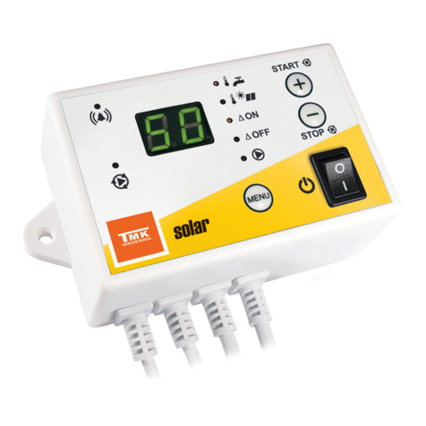
SW 100W is a controller designed for automatically switching on/off the blower operating with a CH boiler.
The controller maintains the temperature level set in the scale, and ensures the combustion of gases
accumulating inside the boiler. After the boiler is extinguished, the blower becomes deactivated, which
reduces energy consumption. The controller is equipped with an additional protective device (a thermal cut-
out) to lower the risk of boiler overheating. The digital display shows the temperature of water in the system.
SW 100W is a very simple-to-operate model.
Technical specifications
- Supply voltage
230V / 50Hz
- Maximum load capacity
100VA
- Range of boiler temperature adjustment
35-90°C
- Temperature measurement range
20-99°C
- Blower hysteresis
2°C
- Duration of blow-through
0-18 s
- Intervals between blow-through operations
6 min

INSTALLATION
1. Mounting of controller
Mount the controller on a suitable wall near the CH boiler using 6 mm wall plugs (the plugs complete with
screws are a part of the delivery set).
2. Mounting of sensor and thermal cut-out
Mount the sensor and the thermal cut-out on a non-insulated pipe going out of the boiler.
Fasten the sensor and the thermal cut-out to the pipe using two clamps (included in the delivery set)
so that they both adhere properly to the pipe.
It is advisable to wrap the pipe with the sensor and the thermal cut-out with a thermal insulation
material.
Note: The sensor and the thermal cut-out are not suited for being used directly in the liquid!
3. Connection of the supply cable to the blower
Connect the green-yellow wire (protective neutral conductor) of the 3-wire supply cable to the protective
neutral terminal of the motor (marked with an appropriate symbol);
Connect the brown and blue wires to the L and N terminals of the motor.
Note: Always ensure that regulator installation is performed by a properly qualified electrician.
4. Connection of the controller
Connect the supply cable to a 230 V, 50 Hz power outlet with an earth contact.
The ambient temperature in the controller mounting location may not exceed 40°C.
Note: The connection cable of the regulator may only be replaced by the manufacturer.

CONTROLLER OPERATION
1. Switch in the “AUTOMATIC” setting
The controller switches the blower on or off depending on the temperature of the sensor.
Use the rotary knob to set the temperature above which the continuous operation of the blower is
automatically switched off.
If the temperature is higher than the set value, the blower switches on for 0÷18 seconds every 6
minutes (periodic boiler blow-through). The time setting can be adjusted using a small screwdriver (one
full rotation corresponds to ca. 1 second) through the opening on the left-hand side of the housing next
to the fuse base (factory setting: 6 seconds).
Note: Blow-through should not be deactivated for safety reasons.
After the CH boiler is extinguished and the temperature drops below 30°C, the continuous operation of
the blower is switched off, and periodic boiler blow-through is deactivated.
If the red indicator is lit, it denotes blower operation.
OnOff
Setting
in scale
Periodic
blow-through Temp.
30°C
2. Switch in the “FIRE UP” setting
If the CH boiler is cold (temperature below 30°C), the blower is switched on to enable the firing of the
boiler.
If the temperature rises above the setting in the scale, the continuous operation of the blower is
switched off (as in the “AUTOMATIC” mode), and periodic boiler blow-through is performed.
On
Setting
in scale
Periodic
blow-through Temp.
30°C
3. If (after boiler firing) the temperature exceeds 30°C, put the switch to the “AUTOMATIC” setting
so that the blower is switched off after the boiler is extinguished.
4. The controller is equipped with an electronic thermometer with a digital display for indicating the
temperature on the boiler (range: 20-99°C).
SAFETY DEVICES
The controller and the blower motor are protected by means of a 500 mA fuse which blows up in emergency
situations (e.g. short-circuit in the motor or in the controller).
An additional protective device is a thermal cut-out which switches off the blower independently of the
controller when the temperature of the boiler exceeds 90°C (the thermal cut-out is switched on again when
the temperature drops by ca. 30°C), e.g. in the event of pump or controller failure.

DELIVERY SET
controller
clamps (2 pcs.)
6 mm wall plugs (2 pcs.)
WARRANTY
TMK sp.j. grants the user a warranty for the SW 100W controller. The warranty period is 3 years from the
date of purchase of the device, however not longer than 4 years from the date of manufacture.
WARRANTY TERMS AND CONDITIONS
Warranty claims shall be accepted provided that the terms and conditions of warranty, and general rules of
operation of electronic devices, are complied with as required. TMK sp.j. guarantees appropriate
workmanship, high quality and reliable operation of the SW 100W controller. In the event of any faults in the
controller’s operation, or defects which can be attributed to the manufacturer, TMK sp.j. shall repair or
replace the faulty controller with a defect-free device within 14 working days from the date of returning the
controller (in person or through post). The warranty scheme explicitly excludes all defects arising due to the
user’s fault and, particularly, defects caused by mechanical damage, faulty mounting, water ingress or
operation of the device contrary to the general rules of operation of electronic devices.
The warranty is only valid with a proof of purchase.
DATE OF SALE: ..........................
day, month, year ..........................
Seller’s stamp and signature
MANUFACTURER:
TMK sp.j.
62-300 Września
Szosa Witkowska 105
tel./fax + 48 61 437 97 60
www.tmk.com.pl ...........................
DATE OF MANUFACTURE
Table of contents
Other TMK Controllers manuals
Popular Controllers manuals by other brands

Samson
Samson TROVIS 5177 Mounting and operating instructions

Eurotherm
Eurotherm SSD Drives 635 Interface manual

Korg
Korg GEC5 user guide

Xantrex
Xantrex SOLAR CHARGE CONTROLLER 30 owner's guide

Mitsubishi Electric
Mitsubishi Electric AJ65DBTB1-32T1 user manual

Danfoss
Danfoss VLT MCD 202 operating instructions