manuals.online logo
Brands
  1. Home
  2. •
  3. Brands
  4. •
  5. Samson
  6. •
  7. Controllers
  8. •
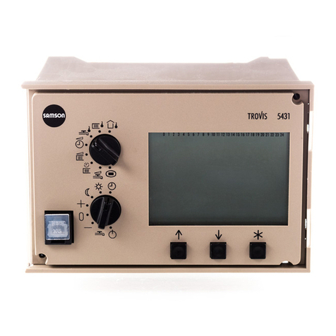
  9. Samson TROVIS 5177 Service manual

Samson TROVIS 5177 Service manual

Automation System TROVIS 5100
Ventilation Controller
TROVIS 5177
Mounting and
Operating Instructions
E 5177 EN
®
Electronics from SAMSON
Firmware version 1.05
Edition September 2000
Contents
1 Scope of the ventilation controller. . . . . . . . . . . . . . . . . . . . 5
2 Safety instructions . . . . . . . . . . . . . . . . . . . . . . . . . . . 6
3 Operation . . . . . . . . . . . . . . . . . . . . . . . . . . . . . . . 7
3.1 Operating controls on front panel . . . . . . . . . . . . . . . . . . . . 7
3.1.1 Mode switch (A) . . . . . . . . . . . . . . . . . . . . . . . . . . . . 7
3.1.2 Selection switch for manual operation (B) . . . . . . . . . . . . . . . .
3.1.3 Changeover key and reset key (C, D) . . . . . . . . . . . . . . . . . .
3.1.4 Set point correction switch (F) . . . . . . . . . . . . . . . . . . . . . .
3.1.5 Arrow keys and enter key (H, I) . . . . . . . . . . . . . . . . . . . . . 9
3.2 Manual operation mode . . . . . . . . . . . . . . . . . . . . . . . . 9
3.3 Control levels . . . . . . . . . . . . . . . . . . . . . . . . . . . . . 12
3.3.1 Info levels . . . . . . . . . . . . . . . . . . . . . . . . . . . . . . . 14
3.3.2 Changing system code number. . . . . . . . . . . . . . . . . . . . . 16
3.3.3 Control method . . . . . . . . . . . . . . . . . . . . . . . . . . . . 19
3.3.4 Parameter levels (PA1 to PA9) . . . . . . . . . . . . . . . . . . . . . 19
3.3.5 Key code . . . . . . . . . . . . . . . . . . . . . . . . . . . . . . . 30
3.3.6 Configuration levels (Co) and function blocks (Fb). . . . . . . . . . . . 31
4 Description of systems . . . . . . . . . . . . . . . . . . . . . . . . 34
5 Function escriptions . . . . . . . . . . . . . . . . . . . . . . . . . 48
5.1 Control method . . . . . . . . . . . . . . . . . . . . . . . . . . . . 4
5.1.1 Supply air temperature control . . . . . . . . . . . . . . . . . . . . . 4
5.1.2 Exhaust air temperature control . . . . . . . . . . . . . . . . . . . . 4
5.1.3 Exhaust air temperature cascade control . . . . . . . . . . . . . . . . 49
5.1.4 Room temperature control . . . . . . . . . . . . . . . . . . . . . . . 50
5.1.5 Room temperature cascade control . . . . . . . . . . . . . . . . . . . 50
5.1.6 Supply air humidity control . . . . . . . . . . . . . . . . . . . . . . 51
5.1.7 Exhaust air/room humidity control . . . . . . . . . . . . . . . . . . . 51
5.1. Exhaust air or room humidity cascade control . . . . . . . . . . . . . 52
5.2 Inputs. . . . . . . . . . . . . . . . . . . . . . . . . . . . . . . . . 53
5.2.1 Setting the type of sensor (Co6 Fb00Fb13) . . . . . . . . . . . . . . 53
5.2.2 Calibrating the sensor (Co6 Fb23) . . . . . . . . . . . . . . . . . . . 53
5.2.3 Analog inputs (Co5 Fb1 Fb21) . . . . . . . . . . . . . . . . . . . 54
5.2.4 Binary inputs . . . . . . . . . . . . . . . . . . . . . . . . . . . . . 54
5.2.5 Analog inputs . . . . . . . . . . . . . . . . . . . . . . . . . . . . . 56
5.3 Outputs . . . . . . . . . . . . . . . . . . . . . . . . . . . . . . . . 57
EB 5177 EN 1
5.3.1 Circulation pump control for the heating coil (BA3) . . . . . . . . . . . 57
5.3.2 Enabling fan speed 1 (BA4) . . . . . . . . . . . . . . . . . . . . . . 57
5.3.3 Enabling fan speed 2 (Co4 Fb02, BA5) . . . . . . . . . . . . . . . . 57
5.3.4 Enabling the cold storage (Co3 Fb12, BA6) . . . . . . . . . . . . . . 5
5.3.5 Binary output dependent on Y3 (Co3 Fb12, BA6) . . . . . . . . . . . . 5
5.3.6 Controlling the chiller (Co3 Fb12, BA6) . . . . . . . . . . . . . . . . 59
5.3.7 Circulation pump control for the HRU (BA7) . . . . . . . . . . . . . . 59
5.3. On/off output of heating coil (Co1 Fb12, BA7) . . . . . . . . . . . . . 59
5.3.9 Three-step output for heating coil (Co1 Fb13; BA6, BA7) . . . . . . . . 60
5.3.10 Fault alarm output (BA1). . . . . . . . . . . . . . . . . . . . . . . . 60
5.3.11 Heating coil (Y1, Co1 Fb21) . . . . . . . . . . . . . . . . . . . . . . 60
5.3.12 Mixed air chamber (Y2, Co5 Fb07, Co2 Fb21, PA2) . . . . . . . . . . 60
5.3.13 Heat recovery unit (Y2, Co2 Fb21) . . . . . . . . . . . . . . . . . . . 63
5.3.14 Humidifier (Y2,Y4, Co4Fb21) . . . . . . . . . . . . . . . . . . . . . 64
5.3.15 Cooling coil (Y3) . . . . . . . . . . . . . . . . . . . . . . . . . . . 65
5.3.16 Air volume control (Co4Fb04, Fb20; Co5Fb1 21, Y4) . . . . . . . . 65
5.3.17 Request for externally required signal over LON (Co1Fb01) . . . . . . . 66
5.4 Time functions. . . . . . . . . . . . . . . . . . . . . . . . . . . . . 6
5.4.1 Summer deactivation . . . . . . . . . . . . . . . . . . . . . . . . . 6
5.4.2 Summer time operation (PA) . . . . . . . . . . . . . . . . . . . . . . 6
5.4.3 Automatic summer time/winter time changeover (Co5Fb16). . . . . . . 69
5.4.4 Public holidays and vacations (PA5) . . . . . . . . . . . . . . . . . . 69
5.4.5 Time schedules (times-of-use) (PA4, PA5) . . . . . . . . . . . . . . . . 69
5.5 Control functions . . . . . . . . . . . . . . . . . . . . . . . . . . . 70
5.5.1 System start-up mode . . . . . . . . . . . . . . . . . . . . . . . . . 70
5.5.2 Summer compensation (PA5) . . . . . . . . . . . . . . . . . . . . . 71
5.5.3 Outdoor temperature-controlled supply air control . . . . . . . . . . . 71
5.5.4 Sustained room temperature (Co5Fb05) . . . . . . . . . . . . . . . . 72
5.5.5 Night purge (Co5Fb17) . . . . . . . . . . . . . . . . . . . . . . . . 73
5.5.6 Air quality control via the mixed air chamber (Co5Fb1 21, PA). . . . 73
5.5.7 Supply air temperature limit (Co5Fb01, Co5Fb1 PA5) . . . . . . . . . 74
5.5. Return air temperature limit (Co5Fb04, PA1) . . . . . . . . . . . . . . 74
5.5.9 Variable return air temperature maximum limit (PA1) . . . . . . . . . . 75
5.5.10 Supply air humidity limit (Co5Fb06, Fb19; PA5) . . . . . . . . . . . . 75
5.6 Controller reaction when faults occur . . . . . . . . . . . . . . . . . . 76
5.6.1 Sensor failure and malfunctions . . . . . . . . . . . . . . . . . . . . 76
2EB 5177 EN
5.6.2 Setting default values . . . . . . . . . . . . . . . . . . . . . . . . . 76
5.7 Protective functions . . . . . . . . . . . . . . . . . . . . . . . . . . 77
5.7.1 Frost protection . . . . . . . . . . . . . . . . . . . . . . . . . . . . 77
5.7.2 Locking settings (Co5Fb23) . . . . . . . . . . . . . . . . . . . . . . 7
5.7.3 Forced operation of the pumps. . . . . . . . . . . . . . . . . . . . . 7
6 LON communication (Co7, PA7, Co5 Fb03) . . . . . . . . . . . . . . 79
6.1 Configuring the LON interface . . . . . . . . . . . . . . . . . . . . . 79
7 Serial interface (Co9) . . . . . . . . . . . . . . . . . . . . . . . . . 81
7.1 Interface versions . . . . . . . . . . . . . . . . . . . . . . . . . . . 1
7.2 Operation with a dial-up modem . . . . . . . . . . . . . . . . . . . 2
7.2.1 Configuring the controller interface. . . . . . . . . . . . . . . . . . . 2
7.2.2 Parameters for operation with dial-up modem (PA9) . . . . . . . . . . 3
7.3 Status register . . . . . . . . . . . . . . . . . . . . . . . . . . . . . 5
7.4 Operation with a dedicated line (bus operation) . . . . . . . . . . . . 6
7.4.1 Bus connection to RS-4 5 interface. . . . . . . . . . . . . . . . . . . 6
7.4.2 Configuring the interface . . . . . . . . . . . . . . . . . . . . . . . 6
8 Memory mo ule . . . . . . . . . . . . . . . . . . . . . . . . . . . 87
.1 Data transfer between controller and memory module . . . . . . . . . 7
9 Installation . . . . . . . . . . . . . . . . . . . . . . . . . . . . . . 88
10 Electrical connection. . . . . . . . . . . . . . . . . . . . . . . . . . 90
11 Technical ata . . . . . . . . . . . . . . . . . . . . . . . . . . . . 93
Appen ix A Lists of function blocks . . . . . . . . . . . . . . . . . . . . . . . . 95
Appendix A.1 Configuration level Co1 for heating coil . . . . . . . . . . . . . . . . 95
Appendix A.2 Configuration level Co2 for heat recovery . . . . . . . . . . . . . . . 95
Appendix A.3 Configuration level Co3 for cooling coil . . . . . . . . . . . . . . . . 95
Appendix A.4 Configuration level Co4 . . . . . . . . . . . . . . . . . . . . . . . . 96
Appendix A.5 Configuration level Co5 of functions affecting all systems . . . . . . . . 97
Appendix A.6 Configuration level Co6 for sensor initialization . . . . . . . . . . . . 101
Appendix A.7 Configuration level Co7 for LON communication . . . . . . . . . . . 102
Appendix A. Configuration level Co for error initialization. . . . . . . . . . . . . 102
Appendix A.9 Configuration level Co9 for Modbus communication . . . . . . . . . . 103
EB 5177 EN 3
Appen ix B Parameters . . . . . . . . . . . . . . . . . . . . . . . . . . . . . 104
Appendix B.1 Parameters set in PA1 level . . . . . . . . . . . . . . . . . . . . . . 104
Appendix B.2 Parameters set in PA2 level . . . . . . . . . . . . . . . . . . . . . . 10
Appendix B.3 Parameters set in PA3 level . . . . . . . . . . . . . . . . . . . . . . 110
Appendix B.4 Parameters set in PA4 level . . . . . . . . . . . . . . . . . . . . . . 111
Appendix B.5 Parameters set in PA5 level . . . . . . . . . . . . . . . . . . . . . . 112
Appendix B.6 Parameters set in PA7 level (LON communication) . . . . . . . . . . . 120
Appendix B.7 Parameter der Ebene PA9 (Modbus) . . . . . . . . . . . . . . . . . 121
Appen ix C Operating level . . . . . . . . . . . . . . . . . . . . . . . . . . . 124
Appendix C.1 Info level InF1 . . . . . . . . . . . . . . . . . . . . . . . . . . . . 124
Appendix C.2 Info level InF2 . . . . . . . . . . . . . . . . . . . . . . . . . . . . 125
Appendix C.3 Info level InF3 . . . . . . . . . . . . . . . . . . . . . . . . . . . . 126
Appendix C.4 Info level InF4 . . . . . . . . . . . . . . . . . . . . . . . . . . . . 127
Appendix C.5 Info level InF5 . . . . . . . . . . . . . . . . . . . . . . . . . . . . 12
Appen ix D Resistance values of temperature sensors. . . . . . . . . . . . . . . 129
Appen ix E Customer ata. . . . . . . . . . . . . . . . . . . . . . . . . . . . 131
In ex . . . . . . . . . . . . . . . . . . . . . . . . . . . . . . . . 142
Key co e . . . . . . . . . . . . . . . . . . . . . . . . . . . . . . 145
Important symbols on the isplay . . . . . . . . . . . . . . . . . . 149
Front view. . . . . . . . . . . . . . . . . . . . . . . . . . . . . . 150
4EB 5177 EN
1 Scope of the ventilation controller
The TROVIS 5177 Ventilation Controller is
designed for controlling and monitoring air
handling systems, ranging from simple air
heaters right up to complex ventilation and
air conditioning systems that contain heating
coils, mixed air chambers, cooling coils,
humidifiers and heat recovery units.
These mounting and operating instructions
will enable you to operate the switches and
keys of this controller as well as give an
explanation of the electrical connection and
mounting procedure. Also the extensive possi-
bilities for configuration and
parameterization are described. Please note
that changes in configuration and
parameterization require specialized knowl-
edge on ventilation technology!
After the controller has been connected to the
power supply, it is basically ready for opera-
tion. Since the controller functions according
to time schedules, make sure the time and
date are set before start-up. Refer to page 22
onwards for step-by-step instructions on how
to set the time and date.
The controller also saves information on con-
figuration and parameters in a memory that
can function for a long time without a power
supply. Only the time and date need to be
reset after a power failure.
The controller contains default setting to oper-
ate the ventilation system from 07.00 to
22.00 hours. If the two-speed fans are acti-
vated, the default setting for time-of-use
between 10.00 and 15.00 hours. If you want
a different time schedule for these setting,
you must change the times-of-use. Refer to
page 26 for details on how to change these
settings.
If you require more information on a certain
topic, use the subject index at the end of
these instructions.
EB 5177 EN 5
Scope of the ventilation controller
2 Safety instructions
4Assembly, start-up and operation of this
device may only be performed by trained
and experienced personnel familiar with
this product. Proper transportation and
storage are assumed.
4The controller is intended for use in elec-
trical power installations. For wiring and
maintenance, you are required to observe
the relevant safety regulations.
4In automatic operating mode (time-con-
trolled operation), the device ensures that
all protective functions that are vital for
the system are monitored. Safety features
such as frost protection monitoring and
excess temperature protection, however,
are not active in the following cases: de-
fective controller and failure of function;
defective sensors or sensors that are not
connected or have not been deactivated;
lack of operating voltage to the controller.
4The installation and electrical wiring de-
scribed in these instructions should only
be performed by authorized personnel.
4Changing function blocks and their pa-
rameters (see Appendix A) requires spe-
cialized knowledge of ventilation systems
and should only be performed by trained
staff.
6EB 5177 EN
Safety instructions
3 Operation
To understand the operation of this control-
ler, use the fold-out page at the end of these
mounting and operating instructions!
The controller is operated over switches and
keys. They are accessible after the clear front
door is opened. The mode switch (A)
switches between the various operating
modes. You can view parameters such as
temperatures and set points using switch (C)
and the keys (H) and (I) as well as determine
the selectable functions and controller param-
eters. During which, you can access the vari-
ous levels described in section 3.3. All set-
tings made and the information required
appear on the display (G).
It is also possible to transfer configuration
and parameterization data with a memory
module in the controller, refer to section .
The following sections contain a description
of the individual switches and keys as well as
concerning the operation of the individual
levels.
3.1 Operating controls on front panel
3.1.1 Mo e switch (A)
Use this switch to select the operating mode:
Automatic operation: Rate opera-
tion/stan -by operation: The control-
ler works according to set times-of-use
and switches between rated and
stand-by operation.
Automatic operation: Rate opera-
tion/re uce operation: The control-
ler works according to set times-of-use
and switches between rated and, in
contrast to previous mode, reduced
operation.
Rate operation: The ventilation sys-
tem is constantly in operation. It is
controlled acc. to the set point(s) for
day, e.g. Supply air day set point.
Re uce operation: The ventilation
system is constantly in operation. It is
controlled acc. to the set point(s) for
night, e.g. Supply air night set point.
Stan -by operation: The ventilation
system is switched off. The frost protec-
tion is active, provided it has been
enabled, see section 5.7.1
Manual operation: In combination
with the selection switch for manual
operation (B), the ventilation controller
can be operated in the manual mode,
see section 3.2.
EB 5177 EN 7
Operating controls on front panel Operation
Y1 Y2 Y3 Y4
1109876542103
3.1.2 Selection switch for manual operation (B)
If the mode switch (A) is set to manual mode
and the manual level is activated, you can
use this switch to operate the output which
you have selected over the selection switch
for manual operation (B), see section 3.2.
Y1 Control output Y1 (heating coil)
Y2 Control output Y2 (humidifier,
mixed air chamber, heat recovery
unit)
Y3 Control output Y3 (cooling coil)
Y4 Control output Y4 (humidifier Anl
and Anl 9)
Pump(s)
Fans (former symbol )
3.1.3 Changeover key an reset key (C, D)
Theses keys must be operated with a pointed
object (e.g. pencil). The following functions
are available:
Changeover key lets you change
between the main levels: operating
and configuration levels.
Reset key resets all parameters in
the parameter level (!) to their
default settings.
3.1.4 Set point correction switch (F)
The set point can be increased or reduced
with the aid of this switch.
−Set point is reduced by 1 K per
raster
0 No change in set point
+ Set point is increased by 1 K per
raster
8EB 5177 EN
Operation Operating controls on front panel
Y1 Y2 Y3 Y4
Y1 Y2 Y3
Y1 Y2 Y3 Y4
Y1 Y2 Y3 Y4
3.1.5 Arrow keys an enter key (H, I)
Arrow keys let you scroll within lev-
els, select parameters and function
blocks as well as increase and
reduce values
Enter key lets you activate levels,
parameters, function blocks as well
as confirm changed values
3.2 Manual mo e
Note!
In manual mode, the user can set the outputs anyway as required. On selecting the man-
ual mode, all limit temperatures and logical links ceased to be in force. The user has ab-
solute control and takes on responsibility for interaction between all the outputs and the
resulting consequences.
As soon as you set the mode switch to the
switch position, all operating states of the
controller outputs are frozen, i.e. the con-
trol signals as well as the switching states of
the binary outputs from automatic operation
are kept regardless of the input variables. If
you have changed the output variables over
manual mode, these states are maintained
until you exit the manual mode.
The system frost protection is guaranteed pro-
vided that the function block Co5 Fb15= ON
is activated.
EB 5177 EN 9
Man al mode Operation
Y1 Y2 Y3
Activating manual mo e
10 EB 5177 EN
Operation Man al mode
Press Display shows Comments
Slide the mode
switch (A) to The display remains unchanged.
Press enter key until Hand appears
on the display.
Press the enter key. The state of the
selected output and the associated
symbol blinking in the schematics
appear on the display. This example
shows Y1 (heating coil) as the selec-
tion switch (B) is positioned at Y1.
Slide the selec-
tion switch for
manual opera-
tion (B) to the
output that
you want to
change!
Y1 Control signal Y1
Y2 Control signal Y2
Y3 Control signal Y3
Y4 Control signal Y4
Pump(s)
Fans
The associated symbol blinks on the
display. Note: - - - appears when
this output is not connected.
24
M
Y1
M
M
Y3 Y1 Y2 Y3
232221201911716151413121110976542103
24
M
Y1
M
M
Y3 Y1 Y2 Y3
232221201911716151413121110976542103
24
M
Y1
M
M
Y3 Y1 Y2 Y3
23222120191171615141312111097654210 3
%
24
M
Y1
M
M
Y3 Y1 Y2 Y3
232221201911716151413121110976542103
%
Exiting manual mo e
EB 5177 EN 11
Man al mode Operation
Press Display shows Comments
Activate the output, observing:
Switch on pumps, fan; increase con-
trol signal
Switch off pumps, fan; reduce con-
trol signal
Note: For two-speed fans, you can
select On1, On2 or OFF.
Optionally When the selection switch (B) is set
to the pump symbol and several
pumps are controlled, e.g. with
Anl 3, use the enter key to select
another pump! The symbol of the
selected pump blinks on the display,
when the pump is switched off, just
the circuit blinks.
Any changes to an output are kept if you push the selection switch for
manual operation (B)!
Sli e Display shows Comments
the mode
switch (A) to
24
M
Y1
M
M
Y3 Y1 Y2 Y3
232221201911716151413121110976542103
%
24
M
Y1
MY1 Y2 Y3
232221201911716151413121110976542103
Y2 M
24
M
Y1
M
M
Y3 Y1 Y2 Y3
232221201911716151413121110976542103
3.3 Control levels
Note!
Any changes in the configuration level (PA and CO levels) may cause errors in the sys-
tem. Therefore, they must be only performed by the specialist!
Fig. 1 shows the level structure in the
TROVIS 5177 Ventilation Controller. It also
shows the operating steps that need to be
taken to access each individual level. The con-
troller contains two main levels: the operat-
ing level and the configuration level. Use the
changeover key (C) to switch between the lev-
els. The operating level contains the info lev-
els, in addition to this, when switched to the
manual mode, a manual level is also accessi-
ble. The configuration level contains the
parameter levels, the system code number
level and the configuration levels. The info,
parameter and configuration levels are
assigned to an index from 1 to 9 which is the
same in all three levels. In this way, specifica-
tions concerning the heating coil are always
termed InF1, PA1 und Co1 (index 1) accord-
ing to the level. All other indices are summa-
rized in the table opposite.
Usually, the ventilation controller is in the
operating level and the time appears on the
display. In Fig. 1, for example, 10:24 is
indicated on the display. Apart from the
time, symbols to represent the operating
mode and operating status as well as the sys-
tem represented symbolically appear on the
display. Refer to page 147 for a summary
of the major symbols.
A bar graph appears on bottom right-hand
corner of the display, showing roughly the
control signals Y1, Y2 and Y3. This bar
graph is shown in the operating level.
Note: Two minutes after the last entry, the
controller returns automatically from the
configuration level back to the operating
level.
Designation
of levels Information,
parameters, functions
InF1, PA1, Co1 Heating coil
InF2, PA2, Co2 Heat recovery unit, mixed air
chamber
InF3, PA3, Co3 Cooling coil
InF4, PA4, Co4 Fans, humidifier
InF5, PA5, Co5 Functions affecting all
systems
Co6 Sensor initialization
PA7, Co7 LON communication
Co Error initialization
PA9, Co9 Modbus communication
Anl System code number and
control method
12 EB 5177 EN
Operation Control levels
EB 5177 EN 13
Control levels Operation
10:24
Hand
InF5
InF4
Manual operation
Functions affecting
all the systems
Function affecting
all the systems
Functions affecting
all the systems
Fans, humidifiers
Fans, humidifiers
Fans, humidifiers
Modbus
communication
Modbus
communication
Error
initialization
Sensor
initialization
LON
communication
LON
communication
Heating coil
Information on: Information on:
Function block
setting for: Parameters for:
Heating coil
Heat recovery,
mixed air chamber
Heat recovery,
mixed air chamber
Heating coil
Heat recovery,
mixed air
chamber
Cooling coil
Cooling coil
Cooling coil
InF1
InF2
InF3
PA1
Co9
Co8
Co7
Co6
Co5
PA2
PA3
PA4
PA5
PA7
PA9
Co4
Anl
Time
Operating
level
Configuration and
parameter level
System code number and control method
Co3
Co2
Co1
Fig. 1 ⋅Control levels
3.3.1 Info levels
Information is displayed in the info levels
(InF1 to InF5) about, for example, the operat-
ing states of the pumps and fans, or control
signals and values of the temperature sen-
sors. The system code number and configura-
tion determine what sort of information is
shown on the display. Refer to Appendix C
for a summary of symbols that appear on the
display and their meanings.
It is not possible to make any changes to
parameters when the controller is in an info
level.
Activating the info level (from the operating level)
14 EB 5177 EN
Operation Control levels
Press Display shows Comments
or Use arrow keys to find the required
InF level (InF1 to InF5)
Press enter key to activate the info
level. The first piece of information
appears on the display. This exam-
ple shows the supply air
temperature.
24
Y1 Y2 Y3
232221201911716151413121110976542103
M
Y1 M
M
Y3
24
Y1 Y2 Y3
232221201911716151413121110976542103
M
Y1 M
M
Y3
°C
Exiting an info level
EB 5177 EN 15
Control levels Operation
Press Display shows Comments
or Every time you press the key,
another piece of information
appears on the display. See page
123 ff for further displays.
On reaching the end of an info
level, End appears on the display.
Press Display shows Comments
both
Any display Press both arrow keys simulta-
neously. The next info level appears
on the display (depending on the sys-
tem code number)
or
When End appears on the display,
press the enter key. In this way, you
can also access the next info level.
24
Y1 Y2 Y3
232221201911716151413121110976542103
M
Y1 M
M
Y3
24
Y1 Y2 Y3
232221201911716151413121110976542103
M
Y1 M
M
Y3
3.3.2 Changing the system co e number
The ventilation controller contains different
types of systems which are assigned to sys-
tem code numbers 0 to 9. They are deter-
mined in the configuration level under Anl
(system code number). By entering the system
code number, you determine both the inputs
and outputs of the controller as well as the
selectable function blocks and parameters.
You can find a list of the different systems in
section 4.
Every change in system code number or con-
trol method (supply air control, exhaust air
control) causes the assignment of sensors to
be reprogrammed: the sensor inputs required
for the function blocks are activated and the
sensor inputs not used are deactivated. These
settings can be changed manually.
Proceed as follows to change the system
code number:
16 EB 5177 EN
Operation Control levels
Press Display shows Comments
Press changeover key! The parame-
ter level PA1 appears on the
display.
or
until
Press arrow keys until Anl appears
on the display. In addition to Anl,
the current system code number
appears. This example shows 1.
24
M
Y1 M
M
Y3 Y1 Y2 Y3
232221201911716151413121110976542103
24
M
Y1 M
M
Y3 Y1 Y2 Y3
232221201911716151413121110976542103
EB 5177 EN 17
Control levels Operation
Press Display shows Comments
Press enter key to activate the system
code number to change it. Anl starts
to blink on the display.
or Select the system code number you
require using the arrow keys. Every
time you press the key, the schemat-
ics depicting the system change on
the display.
Confirm the new system code num-
ber with the enter key. Anl no longer
blinks on the display. However, the
system elements start to blink as well
as one or two arrows to indicate the
control method. This example shows
supply air control.
or Use the arrow keys to select a differ-
ent control method. Each control
method is shown by the arrows on
the right-hand side: in supply air
duct, exhaust air duct, or both, in
the room, or in the room and supply
air duct; this example shows room
control.
24
M
Y1 MY1 Y2 Y3
232221201911716151413121110976542103
Y2 M
24
M
Y1 MY1 Y2 Y3
232221201911716151413121110976542103
Y2 M
24
M
Y1 MY1 Y2 Y3
232221201911716151413121110976542103
Y2 M
24
M
Y1 M
M
Y3 Y1 Y2 Y3
232221201911716151413121110976542103
18 EB 5177 EN
Operation Control levels
Press Display shows Comments
Press the changeover key to change
to operating level.
Press Display shows Comments
Press enter key to confirm the control
method. Co1 appears on the dis-
play. If this is not the case, you have
selected Anl 6, or 9, see the next
step on how to proceed.
For Anl. 6, , 9 the control method for the humidifier control circuit now
appears on the display. The cooling coil and humidifier blink. Set the con-
trol method in the same way as described for the temperature control cir-
cuit. When selecting using the arrow keys, a difference is made between
humidifying and dehumidifying operation mode or just humidifying opera-
tion mode. When the latter applies, just the humidifier blinks on the
display.
24
M
Y1 MY1 Y2 Y3
232221201911716151413121110976542103
Y2 M
24
Y1 Y2 Y3
232221201911716151413121110976542103
M
Y1 M
Y2 M
3.3.3 Control metho
You can choose between the following con-
trol methods for all systems:
4Supply air temperature control,
4Exhaust air temperature control,
4Exhaust air temperature cascade control,
4Room temperature control or
4Room temperature cascade control.
For systems Anl 6, and 9 (air-conditioning
systems) the control method needs to be set
for the temperature control circuit as well as
for the humidity control circuit. For the humid-
ity circuit, you can choose between:
4Supply air humidity control,
4Exhaust air humidity control,
4Exhaust air humidity cascade control,
4Room humidity control or
4Room humidity cascade control.
The difference between temperature and
humidity control circuits is shown on the dis-
play by blinking symbols. For the tempera-
ture control circuit, heating and cooling coil
blink on the display. For the humidity control
circuit, the cooling coil and humidifier blink
on the display. Additionally, for the humidity
control circuit, a difference is made between
humidifying and dehumidifying operation
and just humidifier operation.
You can set the control method in the configu-
ration level under the system code number
Anl. Refer to Changing the system code
number in section 3.3.2 on page 16.
3.3.4 Parameter levels (PA1 to PA9)
In the parameter levels PA1 to PA9, you can
change parameters which have been
enabled by the configuration. The parame-
ters are recognizable by a combination of
symbols that appear on the display. You will
find a summary in Appendix B.
If you want to change parameters, procee as follows:
EB 5177 EN 19
Control levels Operation
Press Display shows Comments
Refer to Appendix B for the parameter levels and the symbols assigned to
the parameter(s).
Press the changeover key to change
to parameter level PA1.
24
M
Y1 M
M
Y3 Y1 Y2 Y3
232221201911716151413121110976542103

Other Samson Controllers manuals

Samson 3374 User manual

Samson

Samson 3374 User manual

Samson 3725 series Service manual

Samson

Samson 3725 series Service manual

Samson 45-9 Service manual

Samson

Samson 45-9 Service manual

Samson TROVIS 5579 Service manual

Samson

Samson TROVIS 5579 Service manual

Samson foundation 3787 Service manual

Samson

Samson foundation 3787 Service manual

Samson 3273 Service manual

Samson

Samson 3273 Service manual

Samson 43-1 Service manual

Samson

Samson 43-1 Service manual

Samson 3767 Service manual

Samson

Samson 3767 Service manual

Samson Carbon 49 User manual

Samson

Samson Carbon 49 User manual

Samson 3371 Series Service manual

Samson

Samson 3371 Series Service manual
Samson TROVIS 5757-7 Service manual

Samson

Samson TROVIS 5757-7 Service manual

Samson 45-6 Service manual

Samson

Samson 45-6 Service manual

Samson 3375 Service manual

Samson

Samson 3375 Service manual

Samson Trovis 6400 Service manual

Samson

Samson Trovis 6400 Service manual

Samson 2357-3 Service manual

Samson

Samson 2357-3 Service manual

Samson 3371 Series Service manual

Samson

Samson 3371 Series Service manual

Samson 44-6 B Service manual

Samson

Samson 44-6 B Service manual

Samson 3730-4 User manual

Samson

Samson 3730-4 User manual

Samson 3277 Service manual

Samson

Samson 3277 Service manual

Samson 42-36 Service manual

Samson

Samson 42-36 Service manual

Samson TROVIS 5573 Service manual

Samson

Samson TROVIS 5573 Service manual

Samson 2357-3 Service manual

Samson

Samson 2357-3 Service manual

Samson 3277 Service manual

Samson

Samson 3277 Service manual

Samson 43-3 Service manual

Samson

Samson 43-3 Service manual

Popular Controllers manuals by other brands

FASTRON. VISION Series Programming guide

FASTRON.

FASTRON. VISION Series Programming guide

Pfeiffer Vacuum IMG 400 operating instructions

Pfeiffer Vacuum

Pfeiffer Vacuum IMG 400 operating instructions

RJX Hobby seriously pro user manual

RJX Hobby

RJX Hobby seriously pro user manual

Nakanishi E4000 CONTROLLER Operation manual

Nakanishi

Nakanishi E4000 CONTROLLER Operation manual

Sentera Controls HPSPX-LP Mounting and operating instructions

Sentera Controls

Sentera Controls HPSPX-LP Mounting and operating instructions

ARAG Bravo 3 Series ADDITION TO INSTRUCTION BOOKLET

ARAG

ARAG Bravo 3 Series ADDITION TO INSTRUCTION BOOKLET

Topcon ISOBUS Artemis Operation manual

Topcon

Topcon ISOBUS Artemis Operation manual

Jamara CR40EP instructions

Jamara

Jamara CR40EP instructions

Milwaukee MC740 user manual

Milwaukee

Milwaukee MC740 user manual

Silicon Laboratories UG268 user guide

Silicon Laboratories

Silicon Laboratories UG268 user guide

Carel FCR3 user manual

Carel

Carel FCR3 user manual

Elko LIC-1 manual

Elko

Elko LIC-1 manual

Swegon P.LEMMENS TAC4 DG Installation and user manual

Swegon

Swegon P.LEMMENS TAC4 DG Installation and user manual

Savch H Series user manual

Savch

Savch H Series user manual

Johnson Controls FEC26 Series installation instructions

Johnson Controls

Johnson Controls FEC26 Series installation instructions

Spectron spectrolab FM45 user manual

Spectron

Spectron spectrolab FM45 user manual

Mueller IOSBUS Ammonia Operation manual

Mueller

Mueller IOSBUS Ammonia Operation manual

YASKAWA CIMR-ZU A Series Programming manual

YASKAWA

YASKAWA CIMR-ZU A Series Programming manual

manuals.online logo
manuals.online logoBrands
  • About & Mission
  • Contact us
  • Privacy Policy
  • Terms and Conditions

Copyright 2025 Manuals.Online. All Rights Reserved.