TMYTEK-NI UD Box 5G User manual

TMYTEK-NI mmWave Device
with NI Ettus USRP X410
Getting Started Guide

Contents
TMYTEK-NI mmWave Solution Package
What’s inside
BBox One 5G
BBox Lite 5G
UD Box 5G
How to setup HW
RF Path Setup
Additional items for RF path setup
RF path configuration
System Control Setup
Additional items for device setup - control path
System control configuration
SPI to HDMI pin define
How to setup SW
Preliminary Setup
Control devices via TMXLAB Kit
UD Box 5G
BBox One 5G and BBox Lite 5G
Control devices by SPI
How to control device in LabVIEW by API
Appendix
. . . . . . . . . . . . . . . . . . . . . . . . . . . . . . . . . . 2
. . . . . . . . . . . . . . . . . . . . . . . . . . . . . . . . . . . . . . . . . . . . . . . . . . . . . 2
. . . . . . . . . . . . . . . . . . . . . . . . . . . . . . . . . . . . . . . . . . . . . . . . . . . . . 3
. . . . . . . . . . . . . . . . . . . . . . . . . . . . . . . . . . . . . . . . . . . . . . . . . . . . . 4
. . . . . . . . . . . . . . . . . . . . . . . . . . . . . . . . . . . . . . . . . . . . . . . . . . . . . . . 6
. . . . . . . . . . . . . . . . . . . . . . . . . . . . . . . . . . . . . . . . . . . . . . . . . . . . . . 7
. . . . . . . . . . . . . . . . . . . . . . . . . . . . . . . . . . . . . . . . . . . . . . . . . . . . 7
. . . . . . . . . . . . . . . . . . . . . . . . . . . . . 7
. . . . . . . . . . . . . . . . . . . . . . . . . . . . . . . . . . . . . . . . 8
. . . . . . . . . . . . . . . . . . . . . . . . . . . . . . . . . . . . . . . . . . . . . 9
. . . . . . . . . . . . . . . . . 9
. . . . . . . . . . . . . . . . . . . . . . . . . . . . . . . . . . 9
. . . . . . . . . . . . . . . . . . . . . . . . . . . . . . . . . . 10
. . . . . . . . . . . . . . . . . . . . . . . . . . . . . . . . . . . . . . . . . . . . . . . . . . . . . 11
. . . . . . . . . . . . . . . . . . . . . . . . . . . . . . . . . . . . . . . . . . . . . . . . 11
. . . . . . . . . . . . . . . . . . . . . . . . . . . . . . . . . . . . . 14
. . . . . . . . . . . . . . . . . . . . . . . . . . . . . . . . . . . . . . . . . . . . . . . . . 14
. . . . . . . . . . . . . . . . . . . . . . . . . . . . . . . 15
. . . . . . . . . . . . . . . . . . . . . . . . . . . . . . . . . . . . . . . . . . . 16
. . . . . . . . . . . . . . . . . . . . . . . . . . . . . . . . . 18
. . . . . . . . . . . . . . . . . . . . . . . . . . . . . . . . . . . . . . . . . . . . . . . . . . . . . . . . . . . . 26
1
TMYTEK.com © TMY Technology Inc.

What’s inside
This document explains how to install, configure, and test the TMYTEK-NI mmWave system.
The mmWave system can transmit and receive signals for various 5G mmWave communica-
tions applications.
UD Box 5G BBox One 5G
RF: 24 - 44 GHz
IF: 0.01 - 14 GHz
Tunable LO: 24 - 44 GHz
Conversion Loss: 13 dB
10 MHz output
100 MHz input/output
API: LabVIEW, MATLAB, Python,
C#, C++
RF: 26.5 - 29.5 GHz
Band: n257, n261
RF Channels: 16
Tx/Rx Half Duplex
Individual Gain and Phase Control
Beam control interface: SPI
API: LabVIEW, MATLAB, Python,
C#, C++
BBox Lite 5G
RF: 26.5 - 29.5 GHz
Band: n257, n261
RF Channels: 4
Tx/Rx Half Duplex
Individual Gain and Phase Control
Beam control interface: SPI
API: LabVIEW, MATLAB, Python,
C#, C++
Model Name Product Number
UD Box 5G
BBox One 5G
BBox Lite 5G
788825-01/788828-01
788823-01/788826-01
788824-01/788827-01
TMYTEK-NI mmWave Solution Package
TMYTEK.com © TMY Technology Inc. 2
TMYTEK.com © TMY Technology Inc.
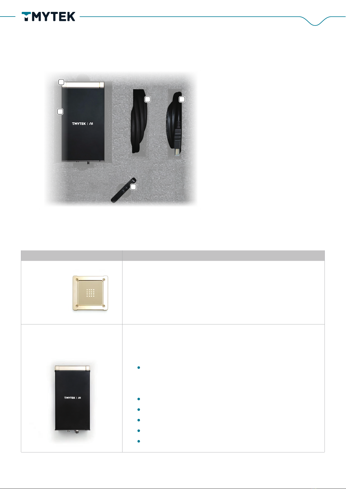
The 16-Channel Phi-A Box is the main part for gain/phase
controlling of BBox One 5G.
Front side:
16 SMPM (female) connectors
Back side:
USB Type-C connector for power supply
Power button
RF com port for RF signal In/Out
SPI proprietary interface for rapid beam steering control
LAN port for control by Ethernet(RJ45)
BBox One 5G
Figure 1. BBox One 5G Contents
1. 4×4 AA-Kit
2. 16-Channel Phi-A Box
3. SPI-N
4. Ethernet cable
5. USB device
5
1
2
43
Component Name Specification /Description
4×4 AA-Kit The 4x4 AA-Kit is a detachable antenna with 16 elements
installed on 16-Channel Phi-A Box by 4 screws on the edge.
16-Channel Phi-A Box
3
TMYTEK.com © TMY Technology Inc.

滾滾長江東逝水
1. USB device
2. R/A plug to plug adapter
3. 4-Channel Phi-A Box
4. Ethernet cable
5. AA-Kit
6. SPI-N
SPI -N The proprietary cable with two heads, HR 25 connector and
HDMI is for connecting the BBox One 5G and the NI Ettus
USRP X410.
(specific type HDMI cable)
The Ethernet cable is for connecting the device and control
host.
Ethernet cable
The USB device contains an installation program, calibration
files, and other relevant documents.
USB device
BBox Lite 5G
Figure 2. BBox Lite 5G Contents
1
2
5
3
4
6
Component Name Specification /Description
4
TMYTEK.com © TMY Technology Inc.

The USB device contains an installation program, calibration
files, and other relevant documents.
USB device
AA-Kit The AA-Kit is a detachable antenna with 16 elements installed
on 4-Channel Phi-A Box by four 2.92-mm (K) Jack connectors.
R/A plug to plug adapter Four right angle 2.92-mm (K) plug to plug adapter is for
connecting the AA-Kit and BBox Lite 5G.
SPI-N The proprietary cable with two heads, HR 25 connector and
HDMI port is for connection the BBox Lite 5G and the NI Ettus
USRP X410
(specific type HDMI cable)
4-Channel Phi-A Box
Ethernet cable The Ethernet cable is for connecting the BBox Lite 5G and the
control host.
The 4-Channel Phi-A Box is the main part for gain/phase
controlling of BBox Lite 5G.
Front side:
Four 2.92-mm (K) Jack connectors
Back side:
USB Type-C connector for power supply
Power button
RF com port for RF signal In/Out
SPI proprietary interface for rapid beam steering control
LAN port for control by Ethernet(RJ45)
Component Name Specification /Description
5
TMYTEK.com © TMY Technology Inc.

Figure 3. UD Box 5G Contents
1. Ethernet cable
2. UD Box 5G Dual
1 2
UD Box 5G Dual
Ethernet cable
Front side:
2 IF ports, 2.92-mm (K) Jack connectors
2 RF ports, 2.4-mm Jack connectors
LED indicator
Back side:
LAN port for control by Ethernet(RJ45)
Power On/Off
DC IN port for DC power supply
100 MHz In/Out port for 100 MHz reference synchronization
10 MHz Out for 10 MHz reference synchronization
+5V/+9V for 5-V and 9-V DC output
Front side
Back side
The Ethernet cable is for connecting the UD Box 5G and the
control host.
UD Box 5G
Component Name Specification /Description
6
TMYTEK.com © TMY Technology Inc.

Equipment included:
RF Path Setup
NI Ettus USRP X410 × 1 UD Box 5G × 1
BBox One 5G × 1
SMA Plug To SMA Plug Cable × 2
RF adapter 2.4-mm Plug to 2.92-mm (K) Jack × 2
2.92-mm (K) Plug to 2.92-mm (K) Plug RF
Cable (DC to 40 GHz) × 2
BBox Lite 5G × 1
Additional items for RF path setup
How to setup HW
7
TMYTEK.com © TMY Technology Inc.

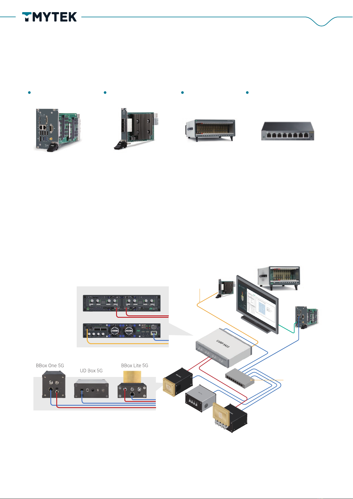
RF path configuration
Connect the NI Ettus USRP X410 transmitter and receiver signal ports to the IF ports of the UD
Box 5G via SMA coaxial cables (blue lines)
Connect the COM port of BBox One 5G/BBox Lite 5G to RF ports of the UD Box 5G via 2.92-mm
(K) coaxial cables (yellow and red lines), please note that 2.92-mm (K) to 2.4-mm adapters are
needed at RF ports of UD Box 5G.
Figure 4. RF Path Architecture
NI Ettus USRP X410
2.4mm Plug to 2.92mm
Jack Adapter
8
TMYTEK.com © TMY Technology Inc.
Additional items for device setup - control path
System Control Setup
PXI controller PXIe-8394 × 1 PXI Chassis Ethernet Switch × 1
System control configuration
The system is supposed to be connected as figure 5, and the steps are:
1. Connect the NI Ettus USRP X410 to all TMYTEK-NI mmWave devices via the Ethernet
Switch, that includes with the BBox One 5G, BBox Lite 5G, and UD Box 5G.
2. Connect the SPI control signal cable to the NI Ettus USRP X410 by HDMI port (option)
Figure 5. System Control Configuration
PXI Chassis
NI Ettus USRP X410
NI Ettus USRP X410 Front
NI Ettus USRP X410 Rear
PXIe-8394
PXI controller
PCIE Gen3 MXI Express Cable
for waveform data
GPIO GPIO
BBox Typical beam steering time:
2 ms of Ethernet
2 us of SPI@100 MHz
Ethernet Switch
BBox One 5G
SPI
SPI
UD Box 5G
BBox Lite 5G
9
TMYTEK.com © TMY Technology Inc.

*SPI control just for BBox One 5G and BBox Lite 5G
SPI to HDMI pin define
HDMI pin number SPI pin define
pin 1
pin 2
pin 4
pin 6
pin 7
pin 9
pin 19
pin 12
pin 15
pin 17
SPI_CSB
Ground
TX_EN
SPI_CLK
SPI_PDI
SPI_SDI
SPI_LDB
SPI_SDO
RX_EN
Ground
10
TMYTEK.com © TMY Technology Inc.
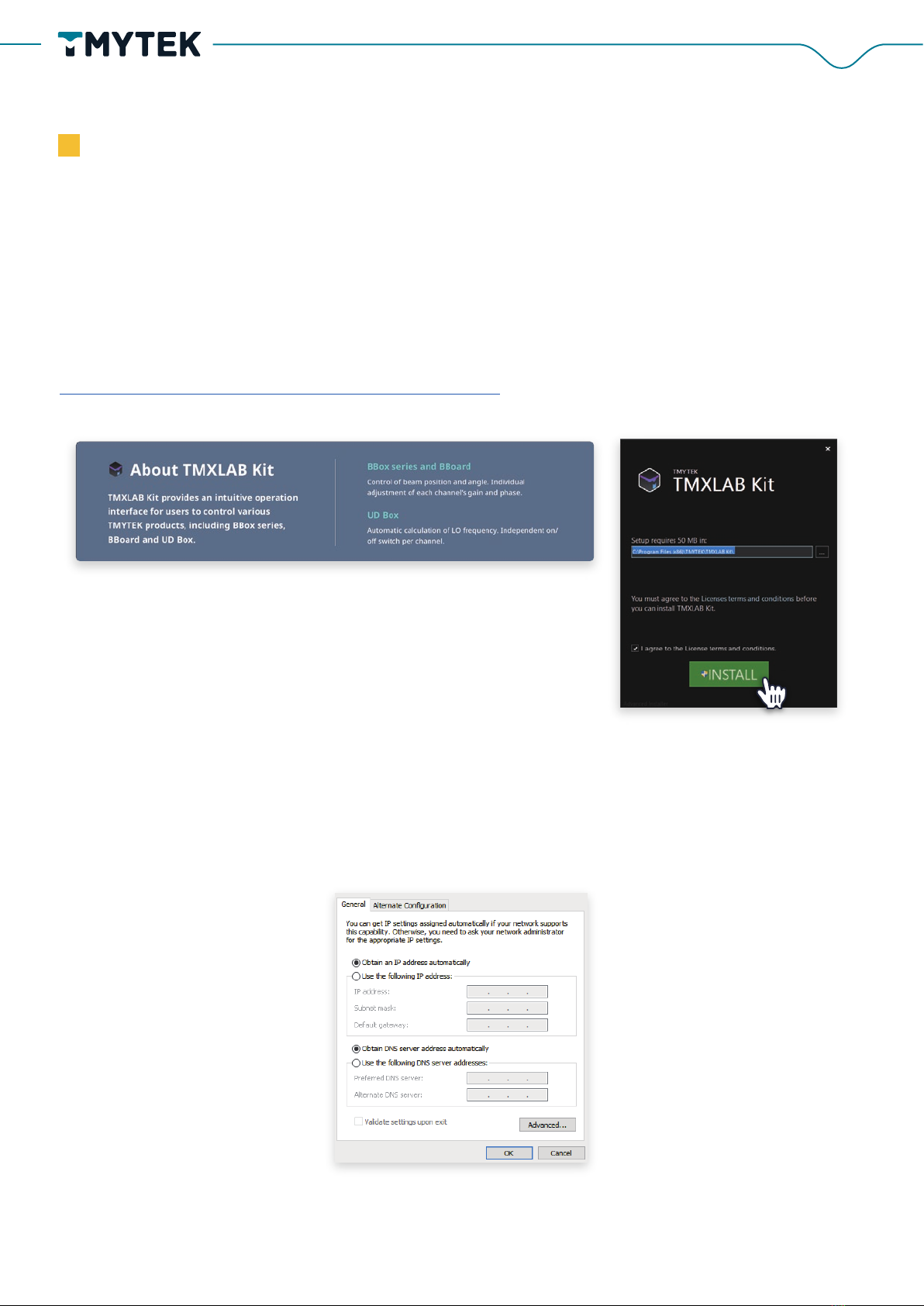
Preliminary setup
Step 1:
Install TMXLAB Kit software and place the calibration files in the specified folder.
You can find the installation file on the USB drive. You may download the latest version from the
TMYTEK website if required
www.tmytek.com/resources/downloads/tmxlab-kit
Step 2: Network Environment Setup
There are 2 types of network topology for setting of multiple devices. If DHCP is supported, con-
figure your control host to "obtain IP address automatically." The IP address could be automati-
cally allocated.
How to setup SW
11
TMYTEK.com © TMY Technology Inc.

If no DHCP function supported, the static IP needs to be configured manually. Please set the
control terminal IP to 192.168.100.xxx and the subnet mask to 255.255.255.0
Be aware that all TMYTEK-NI mmWave device default IP addresses are the same. If you want to
manually set the static IP address, connect one device to the computer via ethernet connection
at a time and follow the instructions below to change the IP address of the device.
You can use TMXLAB Kit to change the static IP.
1. Click the gear in the upper right corner first, and the IP modification interface will appear
as shown below
12
TMYTEK.com © TMY Technology Inc.

2. Be aware that the static IP configured shall not be the same with other devices in the
same subnet.
3. Please enter the static IP address and click the Apply button.
4. Repeat the procedure for all devices if required
Step3: Launch TMXALB Kit.
1. Connect all devices, and turn all TMYTEK-NI mmWave devices on
2. Launch TMXLAB Kit
3. All TMYTEK-NI mmWave devices will be found (shown in the red box as figure
below) after device scanning completely.
*Please press the scanning button again if devices are not found.
13
TMYTEK.com © TMY Technology Inc.
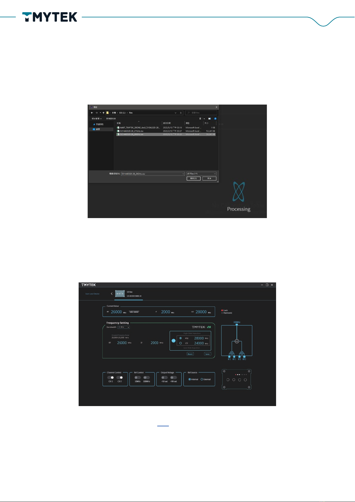
Step4:
Import calibration files from USB device in BBox One 5G and BBox Lite 5G delivery package and
start to use. (Select the calibration file as shown below and import it)
Control devices via TMXLAB Kit
UD Box 5G
1. Set the IF and RF signal frequencies, then choose the corresponding LO frequency.
Please refer to the user manual from the link. Following the chapter 5 instructions for UD Box
5G detailed control procedure.
14
TMYTEK.com © TMY Technology Inc.

Please refer to the user manual from the link. Following the chapter 3 instructions for BBox Lite
5G detailed control procedure.
Please refer to the user manual from the link . Following the chapter 3 instructions for BBox One
5G detailed control procedure.
BBox One 5G and BBox Lite 5G
1. Enter the beam steering angle or drag the beam tip directly
2. Adjust the dB value to control the Beam gain
15
TMYTEK.com © TMY Technology Inc.

Step 1:
Launch TMXLAB Kit and select the beam config editor function. (shown in the red box of the
figure below)
Step 2:
1. Define the gain, theta and phi angle of each Beam ID. There are 64 beam IDs for both Tx
and Rx modes.
2. Please save configuration after complete, it will generate the corresponding .json file in
the “BeamTable” folder.
Control devices by SPI
*SPI control only used for BBox One 5G and BBox Lite 5G
16
TMYTEK.com © TMY Technology Inc.

Note
Step 3:
Write the beam table settings to BBox One 5G and BBox Lite 5G.
Please switch the control method to SPI, then the beam table setting parameters will be written
to the BBox One 5G or BBox Lite 5G by Ethernet.
Step 4:
Trigger the beam steering of a specific beam ID through SPI interface. More details, please
follow the rapid beam control user manual for customized the SPI control host.
Control document and settings via SPI interface
If you want to get a more detailed introduction to the use instructions,
please go to the official website to download the user manual
www.tmytek.com/resources/downloads/tmxlab-kit
17
TMYTEK.com © TMY Technology Inc.

How to control device in LabVIEW by API
TMYTEK provides API examples and API user guide for free download on GitHub. Please refer
to the following website.
https://github.com/tmytek/bbox-api
TMYTEK-NI mmWave Box Series API helps developing mmwave beamforming and beam
switching/steering applications with BBox 5G Series (mmwave beamformer) and UD Box 5G
Series (mmwave Up-down converter). The Dynamic Link Library file (.dll file) release is Win-
dows shared library and tested on visual studio community and LabVIEW.
Every model has its own sample code. Please refer to the sample code inside each folder for
the specific programming language.
Figure 6. Programming Language
a. Please use LabVIEW 2019 or later version
b. If you encounter any calibration tables location problem, please refer to
the troubleshooting topic in
i. Please copy the files from folder, “Calibration Table”, in USB
drive into the location C:\Windows\System32\files, and you
will need to create a folder with the name “files” if necessary.
ii. Please running your application in administrator permission
Note
18
TMYTEK.com © TMY Technology Inc.

Figure 7. LabVIEW Control Example
1. Launch LabVIEW project download from the github link.
2. Please refer to the API documentation for function details
BBox One 5G
Step 1:
Please follow the instructions in the previous section of this document to check the hardware
setup. Make sure your host PC is only connected to one target device. The example is config-
ured to deal with a single device case.
Step 2:
Download the source code project from github and unzip it.
19
TMYTEK.com © TMY Technology Inc.
This manual suits for next models
8
Table of contents
Popular Receiver manuals by other brands


Spectra Precision
Spectra Precision EPOCH 35 user guide

Telstra
Telstra Argent user guide

Megasat
Megasat Megasat HD Camping Receiver comfort user manual

BWI Eagle
BWI Eagle AIR-EAGLE XLT 44P-8-ESTOP Product information bulletin

Lectronics
Lectronics UCR411A instruction manual

PureTools
PureTools PT-HDBT-702-RX user manual