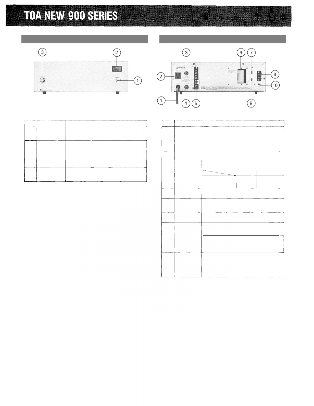
When all connections are completed, turn power switch on. Then,
the meter is illuminated. Approx. 5 seconds after switching power
on, the amplifier comes into operation.
ADJUSTMENT OF VOLUME CONTROL
Adjust the input volume control to obtain appropriate output level.
In normal use of BGM playing or announcement, the deflection of
the meter is recommended to be within the range as indicated in the
drawing. Tone quality will be considerably deteriorated if the
pointer indicates around 0 VU.
To mount the amplifier in a standard 19-inch equipment rack, use
the MB-931 Rack-mounting Bracket accessory.
In normal use of BGM
playing or announcement.
The pointer of meter indicates 0 VU if continuous signals like sine
waves are applied to the input of the amplifier.
Remove 4 screws securing case.
Fix the MB-931 with attached 4 screws.
MB-931 The length of the screws should not
(Silver) exceed 12mm (1/2 inches).
(OPTION)
Perforated Panel
PF-911 (OPTION)
(Silver)
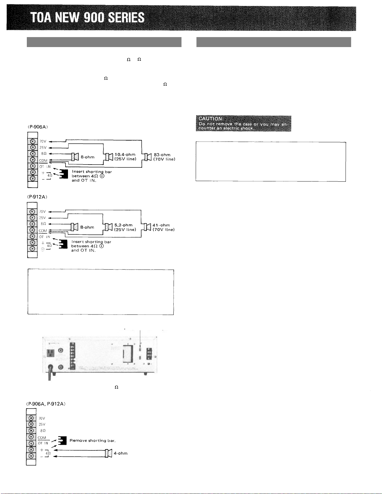
If two or more amplifiers are mounted in
an equipment rack, space should be pro-
vided between the units for ventilation.
The PF-911 Perforated Panel is recom-
mended for this purpose.
Continuous signals
When the power amplifier is used in combination with a mixer pre-
amplifier, adjust the total gain at the mixer preamplifier with the
gain setting of the power amplifier at maximum.
•Output Fuse
Each amplifier has an output fuse to protect the amplifier from
short-circuiting at the output or overloading. Check the fuse when
speakers connected do not sound even if the meter deflects
normally. If the fuse blew, replace with the same type fuse after
confirming the following points.
(1) Speaker cables are not short-circuited or the load does not
exceed the rating specified.
(2) Wiring is correctly done at the output terminal board.
•
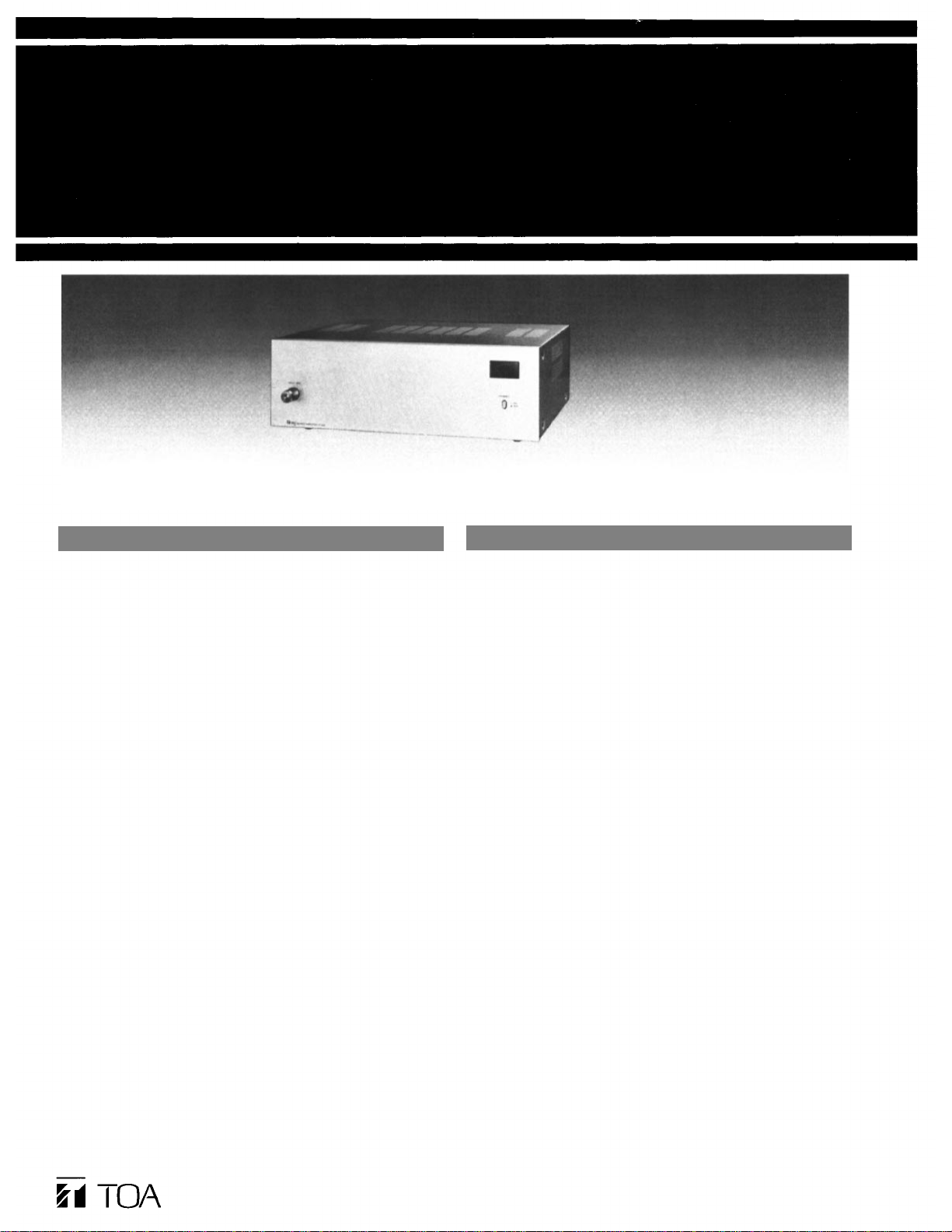
Unpacking
Upon receipt of the amplifier shipment, please inspect for any
damage incurred in transit. If damage is found, please notify your
local TOA representative and the transportation company
immediately.
State date, nature of damage, whether any damage was noticed on
the shipping container, prior to unpacking. Please give waybill
number of shipping order.
•Failure
Should amplifier fail, contact your nearest TOA authorized con-
tractor or service center.
Operation
Rack Mounting
Servicing
— 4 —