manuals.online logo
Brands
  1. Home
  2. •
  3. Brands
  4. •
  5. Toa
  6. •
  7. Microphone
  8. •
  9. Toa HY1 User manual

Toa HY1 User manual

PROFESSIONAL SOUND SYSTEM
Instruction Manual
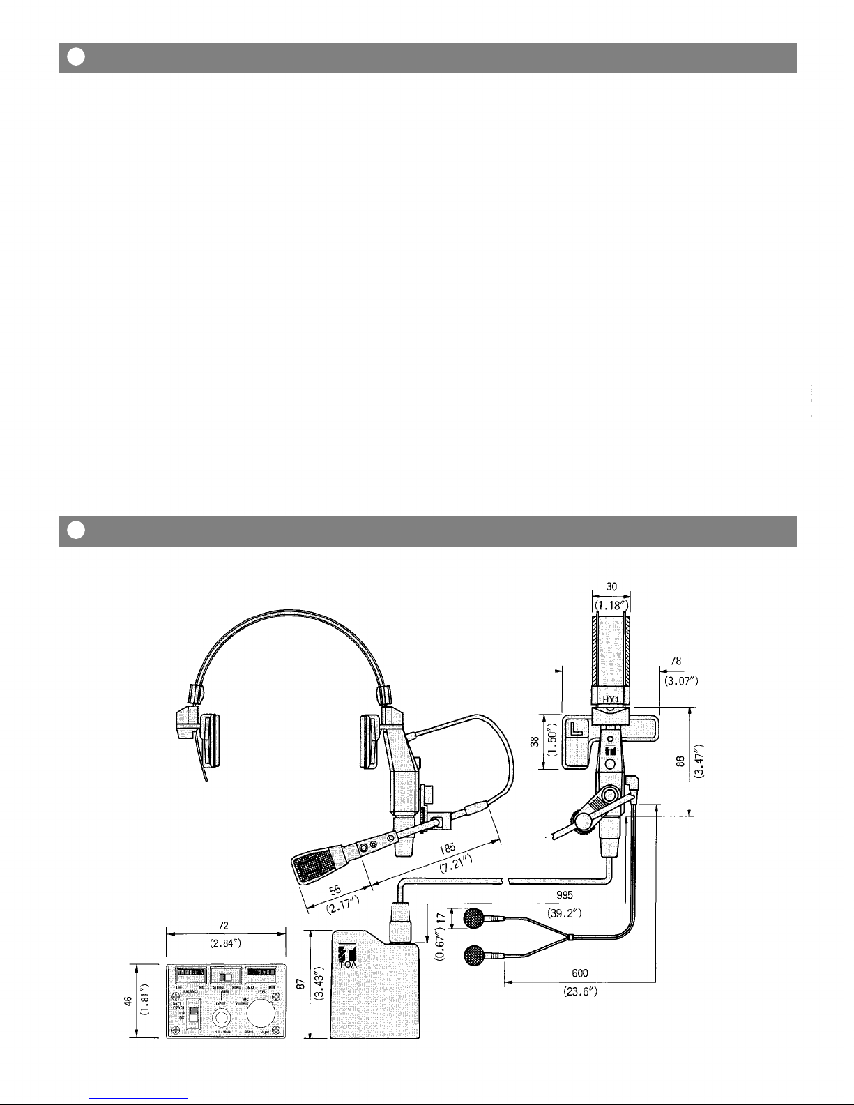
Headset Microphone Model HY1/HY2
GENERAL DESCRIPTION
The TOA HY 1 and HY 2 are headset type microphones
designed for professional level applications in recording, live
sound reinforcement, and roadcast environments. Unlike
the typical handheld or stand mounted mic, the "hands-free"
configuration allows the user to concentrate on the perfor-
mance rather than the microphone. The HY's feature a uni-
que design which provides super performance and num er
of functions never efore availa le. They are ergonomically
designed to ensure comfort and sta ility for sustained
periods of time, without fatigue. The HY 1 and HY 2 are iden-
tical in design and function with the exception of the head-
and. The HY 1 head and is designed for extended wear, and
the HY 2 head and is designed to e hidden in the user's
hair.
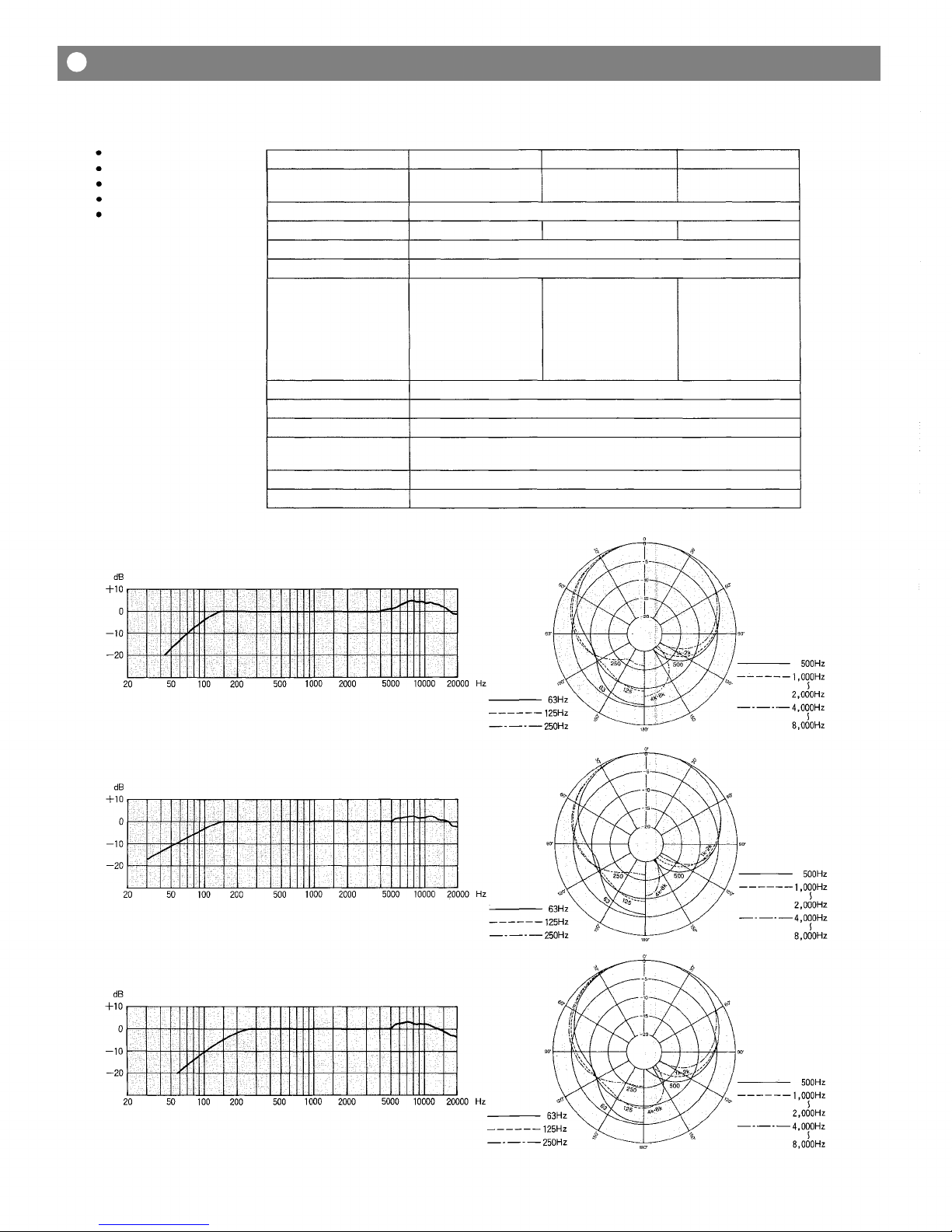
The fixed-charge condenser mic element employs a ack-
electret type design with a gold-vaporized, extremely thin
mem rane (4µm) to provide superior performance and high
sta ility. Frequency response is tailored to roll off the low
end, producing a well alanced low frequency characteristic
and eliminating pro lems associated with "proximity effect."
(Proximity effect causes the mic to accentuate the low fre-
quencies, and in extreme cases may cause the vocal to
sound oomy and muffled.) A cardioid pickup pattern ensures
that surrounding noise is rejected, allowing the vocal to e
clear, clean and distinctive.
The HY headsets are equipped with an interchangea le mic
capsule which is voiced for male vocal response (HMV),
however, optional capsules are availa le. The HFV is voiced
for female or tenor male vocals, and the HCM for limited
andwidth intercommunications. All mic capsules feature a
red LED to give a visual indication of "mic live" status. A
cough utton is also provided on the headset to allow the
user to turn the mic element off when necessary (the LED
goes out).
The HY headsets are equipped with a sturdy eltpack which
provides operating power, mixing, and stereo monitoring
functions. The monitoring system is designed to allow the
user to independently control monitor (fold ack) sends and
personal vocal level through the integral stereo headphone
system, directly from the eltpack. An optional 15 foot exten-
sion ca le (C15-HY) allows the eltpack to e isolated from
the headset. The HY systems may e operated from two 1.5
volt "AA" atteries, or from an external phantom power
supply.
1. Ergonomic "hands-free" design provides secure attach-
ment to user's head, and allows comforta le wear
without fatigue.
2. Smooth, extended "vocal" frequency response, and ex-
cellent transient response.
3. High quality, fixed-charge condenser microphone element
with cardioid pick-up pattern. Interchangea le mic cap-
sules allow precision response tailoring for optimum
vocal performance.
4. Standard version is fitted with mic capsule designed for
male vocal response (HMV). Optional capsules are
availa le for female vocal, or male tenor vocal (HFV), and
limited andwidth intercommunications (HCM).
5. Integral stereo headphone monitoring system for "per-
sonalized" fold ack and cueing functions.
6. Red LED lights to indicate "mic live" status.
7. Cough utton.
8. Headset may e worn from either right or left side.
9. System may e powered from two 1.5 volt "AA" atteries.
or an external phantom power supply.
10. Sturdy eltpack provides operating power, mixing and
monitoring functions.
FEATURES
Assem ly Diagram................................................................................................
Operating Instructions...........................................................................................
Stereo Headphone Monitoring System..............................................................
Capsule Replacement...........................................................................................
HY Applications Guide...........................................................................................
2
3
4
5
5
HY1/HY2 Specifications.................................................................................
Dimensions.......................................................................................................
6~7
7~8
Block Diagram........................................................................................................
8
—
1
—
Contents
HY1 (left-side operation)
HEAD
BAND
COUGH
BUTTON
HEAD
PAD
MIC
ADJUSTMENT
KNOB
MIC
CAPSULE
"HMV"
MIC ARM
ARM HOLDER
BATTERY
COVER
"AA" BATTERY×2
HY2 (left-side operation)
HEAD
BAND
FROM MIXING
CONSOLE
TO MIXING
CONSOLE
—2—
Assembly Di gr m
<Assembly Instructions for left-side oper tion>
1. Assem le the HY headset according to the
assem ly diagram.
(A) Attach the head pad marked "L" to the left side of
the headset, and the head pad marked "R" to the
right side, y pressing firmly until they "snap" into
place.
(B) Connect the interconnecting ca le to the headset
and the eltpack, ensuring that the locking ring of
each connector is fully engaged.
(C) If the internal monitoring system is to e used,
connect the stereo mini plug of the PH 5 head-
phone to the headphone jack of the headset.
(Note: Other stereo headphones with an im-
pedance of 16 ohms or greater may e used if
desired.)
2. Insert the "L" and "R" units of the headphone into
the respective left and right ears as illustrated.
6. Turn the eltpack power switch to "OFF," and
rotate the monitor level volume control to "MIN"
and the monitor alance control to its center pos-
tion. Connect an XLR ca le etween the MIC
OUTPUT of the eltpack, and a low-Z input of a
mixer or sound system. If the integral monitoring
system is to e used, insert a stereo or mono 1/4"
phone plug into the LINE INPUT JACK, and slide
the line mode selector switch to the appropriate
setting.
7. Place the eltpack power switch in the "ON" posi-
tion. Set the COUGH BUTTON to the "ON" posi-
tion, and the red LED will light to indicate "mic
live" status. Rotate the MONITOR LEVEL VOLUME
CONTROL to o tain a desira le level in the head-
phones, and adjust the MONITOR BALANCE CON-
TROL to o tain the proper "mix" etween the direct
vocal and the line input monitor signal.
8. For right-side operation, reverse the positions of the
"L"and "R" head pads. The MIC ARM should e
reversed y carefully pulling the CANTILEVER out
away from the headset (just enough for clearance)
and swinging it to the other side; then gently lower
the arm to the surface of the headset. Orient the
red LED of the mic capsule toward the face, y
first loosening the MIC ADJUSTMENT KNOB, turn-
ing the shaft, and then retightening the kno .
3. Set the cough utton to the "mic off" position.
"mic
on"
position "mic off"
position
4. Position the headset so the "L" and "R" head pads
rest immediately a ove the respective "L" and "R"
ears, and adjust the head and for a comforta le fit.
5. Loosen the mic adjustment kno , and position the
mic capsule approximately 10-25mm (1/2-1 inches)
from the corner of the mouth. Ensure that the can-
tilever is positioned fully downward, and carefully
tighten the mic adjustment kno to hold the mic
arm in the desired location. You should experiment
with the positioning of the mic capsule, in relation
to the mouth, to determine the location that pro-
vides the est reproduction of your individual vocal
tonality and performing style.
Note: The cantilever that connects the mic arm to
the ody of the headset allows you to swing the
mic arm up and away from the face when
necessary, and then reposition the mic arm to ex-
actly the same location when desired.
CANTILEVER
OFF
POSITION
SPECIAL
SCREW
POSITION FOR
LEFT-SIDE
OPERATION
POSITION FOR
RIGHT-SIDE
OPERATION
Oper ting Instructions
— 3 —
The stereo headphone monitoring system was designed to monitor the vocal, direct from the
mic capsule, and mix it with an external line level input signal, such as a monitor (fold ack)
signal from a mixing console. The com ined signals are sent to the stereo headset after eing
amplified y the eltpack's stereo amplifier. This allows the user to adjust his own mixing
alance and master sound level independently of other performers. Disconnecting the head-
phone makes it possi le to use the headset only as a microphone.
The monitoring system is powered y two 1.5 volt "AA" dry cell atteries, which are housed in
the eltpack. To operate the unit, turn the attery power switch to the "ON" position. Please
note that even though the HY headset is designed to operate from an external "Phantom"
power supply, the monitoring system, ecause of its relatively high power requirements, still
requires power from the atteries in the eltpack.
Control P nel Di gr m )
Line Mode
Selector Switch
Monitor Level
Volume Control
Monitor Balance
Control
Battery ———
Power Switch
Mic
Output Connector
Line
Input Jack
B ttery Power Switch and Phantom power supplies :
This switch turns the eltpack attery power supply
on or off. Setting the switch to ON supplies attery
power to the mic capsule as well as to the head-
phone monitoring system. If phantom power is sup-
plied from an external source to the eltpack, the
mic capsule is automatically switched to the exter-
nal source for its operation, regardless of the posi-
tion of the BATTERY POWER SWITCH.
NOTE:
The headphone monitoring system always requires
attery power from the eltpack, due to the
relatively high power requirements common to this
type of system.
Line Input J ck:
This jack accepts any line level input signal, and is
rated +4dB 10K-ohms. The jack would typically e
connected to either a stereo or mono send from a
mixing console. It also serves very well as an input
for a tape deck or other pre-recorded music
source, except a magnetic turnta le. Set the LINE
MODE SELECTOR SWITCH to STEREO or MONO
according to the type of 1/4" phone plug which is
inserted into this jack.
Mic Output Connector:
The vocal signal from the headset microphone is
routed to this XLR connector. The signal availa le
at this output is not affected y the settings of
either the MONITOR BALANCE CONTROL or the
MONITOR LEVEL VOLUME CONTROL. The output
impedance is 250 ohms alanced, and would
typically e connected to a low impedance XLR
connector of a mixing console or powered sound
system.
Line Mode Selector Switch :
The switch setting should e determined y the
type of 1/4" plug (stereo or mono) which is inserted
into the LINE INPUT jack. Place the switch in the
STEREO position when a stereo plug is inserted,
and to MONO when a mono plug is inserted. Set-
ting the switch to the MONO position when a
stereo signal is inserted will cause the "R" signal to
e disconnected from the circuitry, and only the
"L" signal will e heard through the headphones.
Please see the lock diagram for a full understan-
ding of the signal flow path.
Monitor B l nce Control:
This control adjusts the alance or "mix" heard
through the stereo headphone system, etween the
direct vocal from the headset mic, and the line in-
put signal. The volume of the direct vocal in-
creases in relation to the level of the line input
signal as the control is rotated toward "MIC," and
decreases as the control is rotated toward "LINE."
Monitor Level Volume Control:
This control adjusts the volume level heard through
the stereo headphone system. It does not in any
way effect the output of the mic signal through the
MIC OUTPUT connector.
—4—
Stereo He dphone Monitoring System
)
"HMV" c psule ( ccessory)
LOCK SCREW
"HFV" c psule (option)
"HCM" c psule (option)
Loosen the lock screw, replace the mic capsule
carefully, and tighten the lock screw.
LIVE ON-STAGE
BROADCAST PRODUCTION
Monitor send out
(mono or stereo)
vocal mic out
Cue output
(single or dual channel)
producer/director mic out
RECORDING STUDIO
Cue mix out
(stereo or mono)
vocal mic out
VIDEO POST PRODUCTION
Cue output
(stereo or mono)
announcer mic out
HOME RECORDING
COMMERCIAL
Talk ack out
(single or dual channel)
vocal mic out
STAGE CREW COMMUNICATIONS
Talk ack out
(single or dual channel)
com mic out
Communications out
(single or dual channel)
control mic out
INDUSTRIAL
LIVE BROADCAST
Cue/monitor out
(single or dual channel)
announcer mic out
INSTITUTIONAL
Cue/monitor out
(stereo or mono)
Director mic out
HY
in
out
Mixing Console
low-Z input
in
HY
out
Recording Console
alanced input
Porta-Studio
low-Z input
in
HY
out
in
HY
out
Mixing Console
cue input
in
HY
out
Broadcast Console
low-Z alanced
input
in
HY
out
Broadcast Console
cue input
in
HY
out
Recording Console
alanced input
in
HY
out
Communications
Control Center
alanced mic input
in
HY
out
Voice Activated
(computer assisted)
Manufacturing
voice control input
in
HY
out
Mixing Console
cue input
—5—
C psule Repl cement
HY Applic tions Guide
<Construction>
Headset
Mic Capsule "HMV"
Beltpack
Interconnecting Ca le
Stereo Headphone
<Microphone>
Mic c psule
Applic tion
Type
Frequency response
Pol r p ttern
Imped nce
Output levels (.1,000 Hz)
Open circuit voltage
(OdB = 1V/µ ar)
Power level
(OdB=1mW/10µ ars)
EIA rating Gm
(OdB = 1 mW/0.0002µ ar)
Equiv lent noise level
M ximum SPL
Ph sing
Power supply
Current dr in
Output connector
HMV (accessory)
Male vocals
HFV (option)
Female vocals or male
tenor vocals
HCM (option)
Communication
Fixed-charge ( ack-electret) condenser
70-20,000 Hz
60-20,000 Hz
100-20,000 Hz
Cardioid
250 ohms alanced
-77 dB
-57 dB
-149
dB
-74 dB
-54 dB
-146
dB
-77 dB
-57 dB
-149
dB
35 dB (A-weighted)
122dB(at 1,000 Hz 1%THD)
Positive pressure on diaphragm produces positive voltage at pin 2
Two 1 .5 volt "AA" atteries or 9 to 52 volts phantom power supply
(Phantom power supply has automatic priority over atteries)
0.8 mA (9V phantom)-5.3 mA (52V phantom)
XLRM type
HMV c psule Frequency Response
Pol r P ttern
HFV c psule Frequency Response
Pol r P ttern
HCM c psule Frequency Response
Pol r P ttern
— 6 —
HY1/HY2 Specific tions
HY1
<Monitor mplifier>
M ximum output
55mW/ch (18 ohms load 10%THD)
Line input
+4 dB/10 kilo-ohms
("BALANCE": center "LEVEL": max 2mW output)
Frequency response
110-15,000 Hz (mic)
35-15,000 Hz (line input)
Power supply
Two 1.5 volt "AA" atteries
<Stereo he dphones>
Driver unit
ø 15 mm (ø 0.59")
Frequency response
50-20,000 Hz
Imped nce
18 ohms
Sensitivity
102dB/mW
<B ttery life ( lk line b tteries)>
12 hours (maximum monitor level)
60 hours (1mW monitor level)
80 hours (without monitoring)
Batteries should e replaced when the LED
indicator does not light rightly.
<Net weight>
headset: 105 grams (3.7 oz) /HY1
85 grams (3.0 oz) /HY2
Beltpack: 265 grams (9.3 oz) including atteries
HMV capsule: 15 grams (0.5 oz)
Interconnecting ca le: 34 grams (1.2 oz)
Stereo headphone: 10 grams (0.4 oz) including cord
<St nd rd ccessories>
Hard case
Special screwdriver
<Option l ccessories>
HFV: Replacement capsule for female or tenor male
vocals
HCM: Replacement capsule for communication
C15-HY: Extension ca le (15 ft)
C15-M: XLR to XLR ca le (15 ft)
C20-M: XLR to XLR ca le (20 ft)
Dimensions
HY1/HY2 Specific tions
— 7 —
HY2 (s me s th t of the HY1 except the he dset)
PHANTOM
PRIORITY CIRCUIT
REGULATOR
PHANTOM
POWER
COUGH
BUTTON
LED
MIC
UNIT
BATT
POWER
SW.
OUTPUT
TRANSFORMER
MIC
OUTPUT
MONO
STEREO
LINE
INPUT
BALANCE
LINE
SW.
LEVEL
STEREO
HEADPHONE
MIC
LINE
—8—
Dimensions
Block Di gr m
Printed in Japan
133-04-168-80

Other manuals for HY1

1

This manual suits for next models

1

Other Toa Microphone manuals

Toa WM-D5200 User manual

Toa

Toa WM-D5200 User manual

Toa WM-5270 User manual

Toa

Toa WM-5270 User manual

Toa WM-5220 User manual

Toa

Toa WM-5220 User manual

Toa WM-290 User manual

Toa

Toa WM-290 User manual

Toa WM-5265 User manual

Toa

Toa WM-5265 User manual

Toa WM-5270 User manual

Toa

Toa WM-5270 User manual

Toa AM-1B Mounting instructions

Toa

Toa AM-1B Mounting instructions

Toa DM-1500 User manual

Toa

Toa DM-1500 User manual

Toa WM-4310 User manual

Toa

Toa WM-4310 User manual

Toa WM-280 User manual

Toa

Toa WM-280 User manual

Toa WM-220 User manual

Toa

Toa WM-220 User manual

Toa EM-370HS-AS User manual

Toa

Toa EM-370HS-AS User manual

Toa EM-700 User manual

Toa

Toa EM-700 User manual

Toa EC-100M User manual

Toa

Toa EC-100M User manual

Toa WM-5320 User manual

Toa

Toa WM-5320 User manual

Toa IP-A1 Series User manual

Toa

Toa IP-A1 Series User manual

Toa HY1 User manual

Toa

Toa HY1 User manual

Toa EM-600 User manual

Toa

Toa EM-600 User manual

Toa DM-524B User manual

Toa

Toa DM-524B User manual

Toa EM-371HS-AS User manual

Toa

Toa EM-371HS-AS User manual

Toa RM-1200 User manual

Toa

Toa RM-1200 User manual

Toa WM-4200 User manual

Toa

Toa WM-4200 User manual

Toa WM-3210 User manual

Toa

Toa WM-3210 User manual

Toa WM-5320 User manual

Toa

Toa WM-5320 User manual

Popular Microphone manuals by other brands

Synco G2 (A1) user manual

Synco

Synco G2 (A1) user manual

Boya BV-V01 manual

Boya

Boya BV-V01 manual

Sven MK-950 user manual

Sven

Sven MK-950 user manual

Audio Technica UniPoint AT857AMa Product information

Audio Technica

Audio Technica UniPoint AT857AMa Product information

Earthworks QTC50 user guide

Earthworks

Earthworks QTC50 user guide

Axis 2N SIP Mic user manual

Axis

Axis 2N SIP Mic user manual

Sennheiser ME 62 manual

Sennheiser

Sennheiser ME 62 manual

TIE USB Studio Desktop Microphone Pro user manual

TIE

TIE USB Studio Desktop Microphone Pro user manual

Shure KSM9HS user manual

Shure

Shure KSM9HS user manual

Sennheiser BF 5048P Instructions for use

Sennheiser

Sennheiser BF 5048P Instructions for use

ETC VS-61 installation guide

ETC

ETC VS-61 installation guide

Extron electronics VLP 102 Setup guide

Extron electronics

Extron electronics VLP 102 Setup guide

Nady Systems Center Stage Dynamic Microphone manual&nbsp;

Nady Systems

Nady Systems Center Stage Dynamic Microphone manual&nbsp;

Reloop sPodcaster instruction manual

Reloop

Reloop sPodcaster instruction manual

Polycom PowerMic Installation

Polycom

Polycom PowerMic Installation

Watchguard CHG400 user guide

Watchguard

Watchguard CHG400 user guide

Shure Sonobar 488A datasheet

Shure

Shure Sonobar 488A datasheet

Lauten Audio Eden LT-386 operating manual

Lauten Audio

Lauten Audio Eden LT-386 operating manual

manuals.online logo
manuals.online logoBrands
  • About & Mission
  • Contact us
  • Privacy Policy
  • Terms and Conditions

Copyright 2025 Manuals.Online. All Rights Reserved.