Toa PC-245AB-EB User manual

FLUSH MOUNT
PC-245AB-EB
CEILIING SPEAKER
Thank you for purchasing TOA's Wall Mount Speaker.
Please carefully follow the instructions in this manual to ensure long, trouble-free use of your equipment.
TABLE OF CONTENTS
1. SAFETY PRECAUTIONS ......................... 1
2. GENERAL DESCRIPTION
AND FEATURES ........................................2
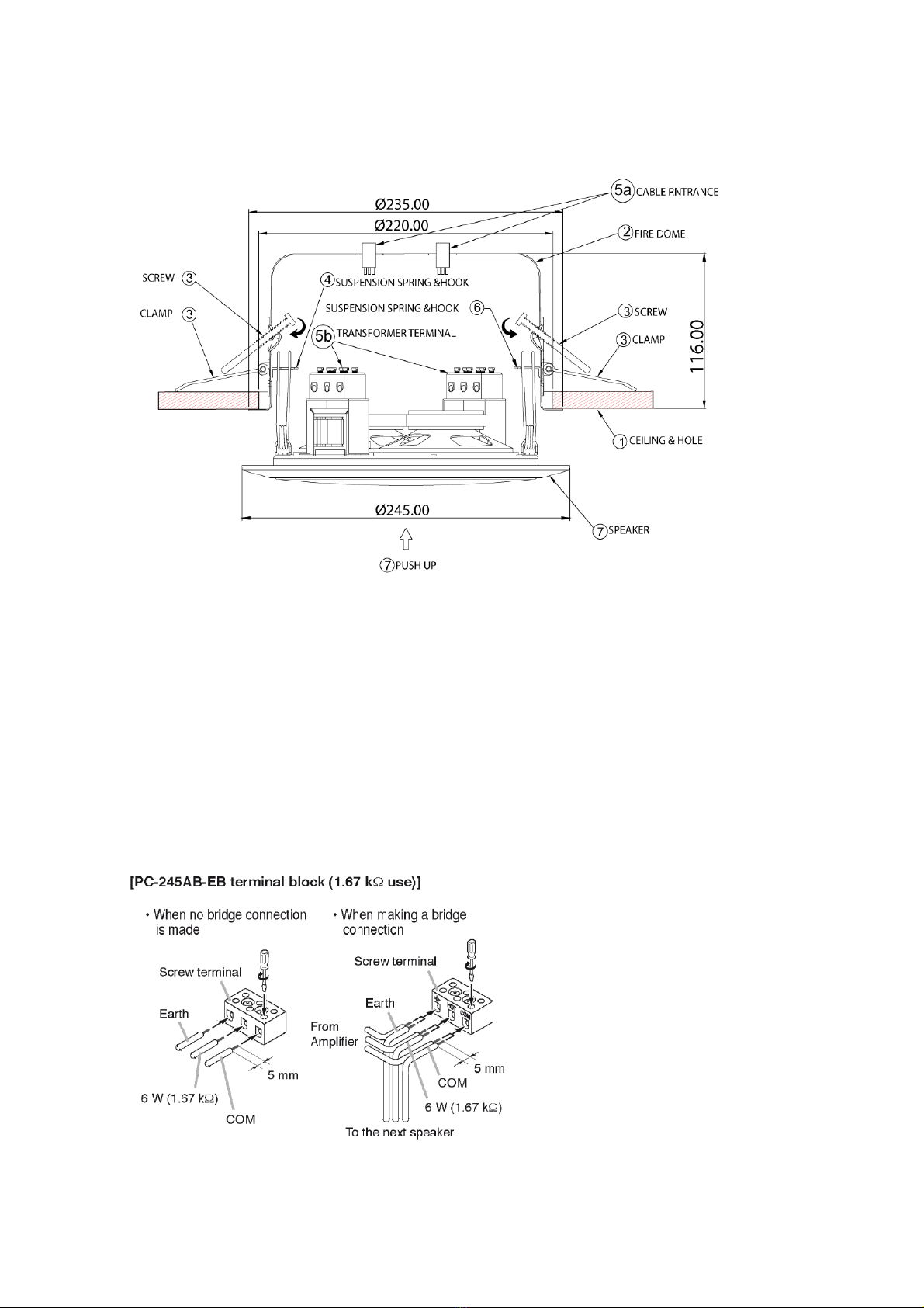
3. INSTALLATION ......................................... 3
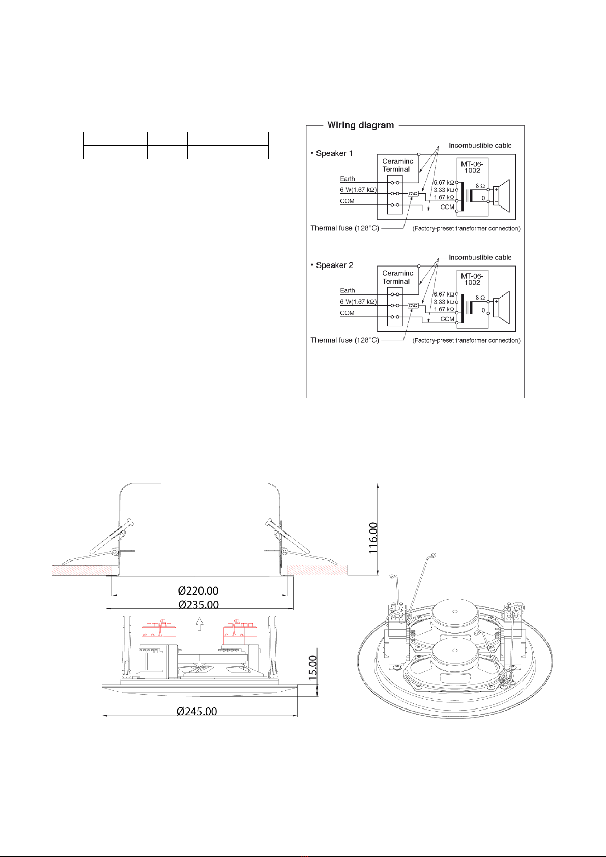
4. DIMENSIONAL DIAGRAM.........................4
5. POLAR PATTERN .......................................5
6. FREQUENCY RESPONSE ..........................5
7. SPECIFICATIONS .......................................5
1. SAFETY PRECAUTIONS
Before installation or use, be sure to carefully read all the instructions in this section for correct and safe
operation.
Be sure to follow all the precautionary instructions in this section, which contain important warnings and/or
cautions regarding safety.
After reading, keep this manual handy for future reference.
When Installing the Unit
Refer all installation work to the dealer from whom
the speaker was purchased. Installation work
requires extensive technical knowledge and
experience. The speaker may fall off if incorrectly
installed, resulting in possible personal injury.
Install the speaker only in a location that can
structurally support the full weight of the unit and
mounting bracket. Doing otherwise may result in
the speaker falling down and causing personal
injury and/or property damage.
Since the unit is designed for in-door use, do not
install it outdoors. If installed outdoors, the aging of
parts causes the unit to fall off, resulting in personal
injury. Also, when it gets wet with rain, there is a
danger of electric shock.
Do not use other methods than specified to install
the speaker. Extreme force is applied to the
speaker and the speaker could fall off, possibly
resulting in personal injuries.
Use screws that are appropriate for the wall's
material and structure. Failure to do so may cause
the speaker to fall, resulting in material damage
and possible personal injury.
Ensure that all screws are securely tightened. If
they are loose after installation, the speaker could
fall down, possibly resulting in personal injury.
Do not mount the speaker in locations exposed to
constant vibration. The speaker or its mounts can
Traceability Information for Europe (EMC directive 2004/108/EC)
Manufacturer: Authorized representative:
TOA Corporation TOA Electronics Europe GmbH
7-2-1, Minatojima Nakamachi, Chuo-ku, Kobe, Hyogo, Suederstrasse 282, 20537 Hamburg,
Japan Germany
INSTRUCTION MANUAL
WARNING
Indicates a potentially hazardous situation which,
if mishandled, could result in death or serious
personal injury.
………………..6

be damaged by excessive vibration, potentially
causing the speaker to fall, which could result in
personal injury.
Do not use anti-rust lubricant. If it contacts resin or
rubber parts, they could deteriorate and cause the
speaker to fall, possibly resulting in personal injury.
Do not install the speaker in indoor swimming
pools or such locations where liquid chemicals are
used. The parts deteriorate if corroded, causing
the speaker to fall, which could result in personal
injury.
When the Unit is in Use
If any of the following irregularities occurs,
immediately switch off the amplifier's power, and
inform the shop from where the speaker was
purchased. Further using the speaker may result in
fire or electric shock.
· If you detect smoke or a strange smell coming
from the speaker
· If water or any metallic object gets into the
speaker
· If the speaker falls, or the speaker case breaks
To prevent a fire or electric shock, never open nor
remove the speaker case. Refer all servicing to
your nearest TOA dealer.
When Installing the Unit
Avoid touching the speaker's sharp metal edge
to prevent injury.
To avoid electric shocks, be sure to switch off
the amplifier's power when connecting
speakers.
When the Unit is in Use
Do not operate the speaker for an extended period
of time with the sound distorting. Doing so may
cause the speaker to heat, resulting in a fire.
Do not stand or sit on, nor hang down from the
speaker as this may cause it to fall down or drop,
resulting in personal injury and/or property
damage.
Have the speaker checked periodically by the shop
from where it was purchased. Failure to do so may
result in corrosion or damage to the speaker or the
mounts that could cause it to fall, possibly causing
personal injury
CAUTION
Indicates a potentially hazardous situation which,
if mishandled, could result in moderate or minor
personal injury, and/or property damage.
2. GENERAL DESCRIPTION AND FEATURES
The PC-245AB-EB is certified according to the European Standard EN 54-24: 2008 and the International
Standard ISO 7240-24: 2010.
Integrated with two speaker units and firedome, the PC-245AB-EB Ceiling Mount Speakers is of metallic
construction and ideal for use in a voice alarm system. The spring catch mechanism allows easy speaker
mounting to the ceiling. The input impedance can be easily selected by changing the tap position of the
transformer. The screw terminal (steatite) makes input cable connections easy and allows bridge wiring.
This model features:
Firedome prevents passing the flames into the ceiling.
2 separate 100 V transformer and 2 speaker.
Easy installation.
A/B wiring.
EN 54-24 certified + BS 5839 Part 8.
Two ceramic screw terminals (steatite) for easy cable connections and two thermal fuses.
Fire resistance according to UL 94-V0.
2

3. INSTALLATION
Step 1. Cut a hole of 220 mm diameter in the ceiling. Use appropriate tools.
Step 2. Insert the cables through the cable entrances. Place the firedome in the hole.
Step 3. Fix the clamps with the attached screws.
Step 4. Insert one of the speaker springs into the receptacle of the firedome.
Step 5. Make wiring.
Insert the lead-in cables (cables from the amplifier) and lead-out cables (cables to other speakers) into
the screw terminals attached to the speaker unit for each of the two built-in speakers.
Unit: mm
3

Insert the fastens fitted at the ends of the HOT and COM cables from the screw terminals at the rear
of the speaker unit into the taps of the matching transformer. Connect the COM cable to the
transformer's COM tap, and the HOT cable to the desired transformer's input tap (Refer to the figure
below.
The table below shows the relationship between impedance and input power.
Matching transformer connection
Impedance
1.67 kΩ
3.33 kΩ
6.67 kΩ
100 V line
6 W
3 W
1.5 W
Step 6. Insert the other speaker spring into
the receptacle of the firedome
Step 7. Push the speaker into the fire pot.
Push the baffle slightly into the cabinet.
4. DIMENSIONAL DIAGRAM
4

5. POLAR PATTERN
6. FREQUENCY RESPONSE (1 W, 1 m)
Single Speaker Double Speaker
7. SPECIFICATIONS
Model
PC-245AB-EB
BS-678BSW
Standards
Certified to the European Standard EN 54-24: 2008 EN 54-24 Certificate
Loudspeaker for voice alarm systems 1488/CPD/0335/W
for fire detection and fire alarm systems
In compliance with the British Standard BS-5839-8: 2008
Environment Type
Type A
Rated Noise Power
2x 6 W (100 V line)
Rated Impedance
100 V line: 1.67 kOhm (6 W), 3.33 kOhm (3 W), 6.67 kOhm (1.5 W)
Sensitivity
S.P.L.
91 dB (1 W, 1 m)
102 dB (1 W, 1 m, 2 speaker)
Frequency Response
150 Hz –20 kHz (–10 dB from sensitivity)
Coverage Angle (–6 dB)
Horizontal: 180° (500 Hz), 170° (1 kHz), 170° (2 kHz), 140° (4 kHz)
Vertical: 180° (500 Hz), 170° (1 kHz), 110° (2 kHz), 160° (4 kHz)
Speaker Component
2x: 8 x 12 cm (3“ x 5") cone speaker
Operating Temperature
-10°C …. + 55°C
Cable Connection
Screw terminal (ceramic)
Applicable Cable Size
Conductor size : 0.8 –2.5 mm2(cross section)
Finish
Baffle, Cabinet, Firedome: Steel, white paint
Dimensions
245 (dia) x 131 (D) mm (9,64“ x 5,16“)
Weight
2.05 kg (4,52 lbs)
IP Grade
IP 32
Notes
The design and specifications are subject to change without notice for improvement.
The Specifications data was measured in an anechoic chamber, according to EN 54-24.
Reference axis: Axis is on the center of grill surface and perpendicular to the grill surface.
Reference plane: Plane is on the grill surface and perpendicular to the reference axis.
Horizontal plane: Plane is containing the reference axis and perpendicular to the reference plane
Horizontal polar diagram
Vertical polar diagram
5


100
45


TOA

TOA

10
TOA
10

URL: http://www.toa.eu/
1309-TEE-004
Table of contents
Languages:
Other Toa Speakers manuals
Popular Speakers manuals by other brands

thomann
thomann THE BOX MBA120W MKII user manual

Polk Audio
Polk Audio Blackstone TL1 Setup guide

Magnat Audio
Magnat Audio MONITOR SUPREME 2000 owner's manual

ACOUSTIC SOLUTIONS
ACOUSTIC SOLUTIONS 4144845 instruction manual

Amphion
Amphion Krypton3X Reference manual

Basalte
Basalte 502-0 Series installation manual