Tobe EPS-LD SafePark Instruction manual
EPSEPS®®-LD SafePark-LD SafePark
parking-aid with invisible antenna
- sensor inside the plastic bumper -
and with audio-visual warnings
- to signal approaching obstacles -
By its
invisible antenna sensor, which covers the whole bumper,
EPS
®emits electromagnetic waves of low energy to generate an
unbroken zone of protection all around the bumper
(FIG. 1).
Thus EPS
®is able to detect approaching obstacles, which enter
into this approx. 50 cm wide zone: All kind of shapes and nearly
all materials (
NOTE: except dry "insulators" like glass, ceramics,
plastic, dead wood) are signalized by
multi-grade warnings.
Activated automatically by engaging the reverse gear
(or in
case of front bumper manually by a switch), EPS
®-LD confirms its
correct power supply by lighting the red logo (car picture) on the
display. Checking at soon itself,
EPS®-LD must confirm its
regular operation capability by a single tone
(= OK-signal).
Only after
OK-signal EPS®-LD is ready to signalize obstacles.
NOTE
: By beeping continuously at activation (= DEFECT-signal)
EPS
®-LD informs that it cannot operate, because its installation
must be repaired (for instance the antenna connection).
ALARM SIGNAL
ALERT SIGNAL
RISK OF CONTACT
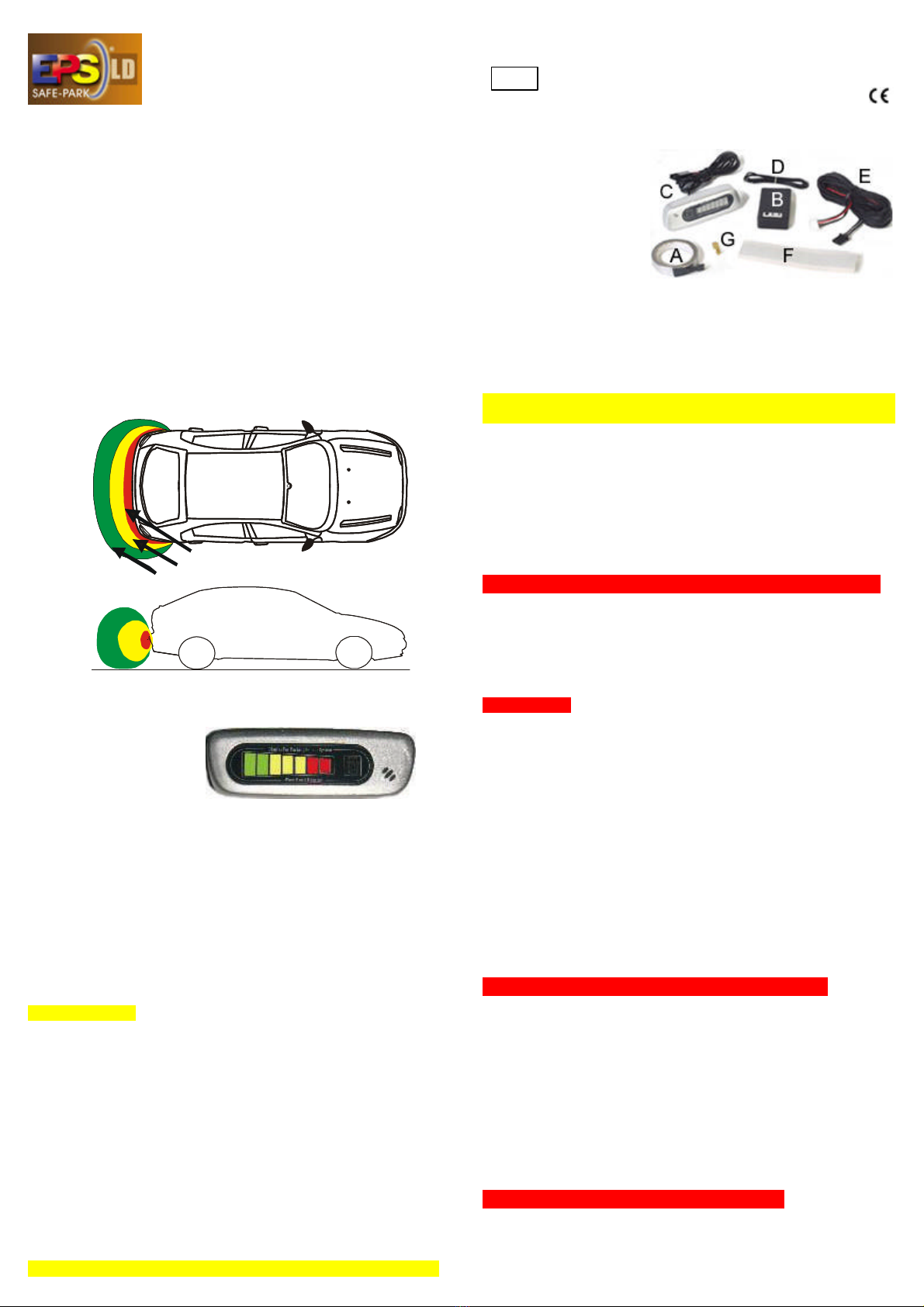
7 colored LEDs
(FIG. 2) and acoustic beeps signalize the
obstacle, when its distance to the antenna (bumper) is decreasing.
First, the 2 green LED light on to ALERT
that the distance to the
approaching obstacle is already below 40-60 cm. Simultaneously
the buzzer starts beeping.
NOTE: All cm values stated here depend
on the type of obstacle, and correspond to the bumper's central
zone, while on its edges theses values (distances) are inferior.
Then, the 3 yellow LED light on to ALARM
when the obstacle
arrives in proximity of the bumper at distances of 15-30 cm, and
the acoustic beeps are emitted now a little bit more rapidly.
Finally, the 2 red LED light on to signalize RISK OF CONTACT
when an obstacle is very near to the bumper (0-15 cm), and the
beeps are emitted now most rapidly.
:
IMPORTANT::
•
Since EPS®assists to use the very last centimeters, very
slow and wary manoeuvring has to be implied !
•
Water flowing down the bumper (high moisture weather
or rain) can cause "false alarms". Thereby EPS®reduces
considerably its sensibility (its range of detection), and from now
on it signalizes permanently at least alert-mode.
•
Without causing warning signals, you can manoeuvre with
(trailer) hook haul or in parallel to a side wall, since their
distances to the antenna do not decrease.
•
If the street coat approaches to the antenna (braking, high
speed, road's unevenness or...), warning signals can be caused.
•
When manoeuvring, even if assisted by EPS®, the driver is
still obliged to inspect carefully the surroundings, in order to
prevent and not to cause any damages.
BEFORE USE, READ AND OBSERVE ALL INSTRUCTIONS.
TECHNICAL DATATECHNICAL DATA
operation voltage 10.5 to 18 V
average current absorbed 50 mA
operation temperatures -
40°C to +85°C
FITTING -COMPONENTS (supplied)FITTING -COMPONENTS (supplied)
Antenna ribbon (A),
self-adhesive, to be
tightly fitted onto the
inside-surface of the
exterior plastic bumper
sheath - covering the
whole width of the car
as well as its corners.
Central unit (B): in mm 59··34··16, to be fixed in the car trunk in a
dry place, as close as possible tothe connection to
antenna-ribbon.
Display (C): to be fitted on the rearview mirror, or dashboard, or....
Antenna-flex (D), wiring (E), mastic (F), flat connector (G).
.. INSTALLATIONINSTALLATION
..
•EPS®
can only operate properly, if the antenna-sensor is
tightly fixed on a well cleaned surface in an optimum position!
•
Do not position the antenna near to metal of the car, since
metal (bumper or reinforcement) close to the antenna can
reduce very strongly the detection range of EPS®!
•EPS®
only suits for plastic bumpers, but for back bumpers
as well as front bumpers, whether enamelled or not.
.1. .FIND A GOOD ANTENNA POSITION:.
Before disassembling the bumper,
find and ascertain the
optimum position for the antenna-sensor by an initial test:
By adhesive tape fix outside onto the bumper any (appr. 2m long)
wire, and connect it as a provisional antenna to both leads of the
antenna-flex twisted together and to the central unit, which for the
rest only must be connected to the display, to +12V and ground.
.CRITERIA:.Note that the antenna must:-
•cover the whole width of the car and its corners
•be the outermost exterior line of the car
•be minimum 3 cm far from metal parts of the car structure
•be minimum 40 cm, better 50 cm above road level
•be minimum 20 cm, better 30 cm away from the wheels
in order to obtain optimum detection range, to avoid reduction of
the detection range by influence of metal, and to avoid false
alarms by approach of road level or turning wheels.
Now test the range of EPS®
by approaching your hands to your
provisional antenna.
If you verify proper detection range (starting at about 50 cm),
mark
the ascertained position
and course of the provisional antenna in
order to fix there (on the corresponding inside-surface) later on the
antenna-ribbon.
- Otherwise repeat that procedure with another antenna position.
.2. .BUMPER AND CENTRAL UNIT:.
Disassemble the exterior sheath of the plastic bumper
, and
uncover its inside surface. Multi-layer or shock-relief materials, if
existing, have to be cored or removed temporarily.
On that side, where the reversing lamp is present, and as close as
possible to the end or corner of the bumper, find (or drill) an
opening hole to thread through the antenna-flex
. Inide the trunk
plug its 2-pin-connector into the central unit, whereas outside twist
together both its leads and pinch them into the male flat connector.
Fix the central unit inside the car
close to that hole of passage,
in a dry place on a cleaned surface, and by means of mastic.
.3. .CLEAN BUMPER'S INSIDE:.
Before fitting the antenna in the position ascertained (1.),
clean
and degrease thoroughly the inside surface of the bumper by
using non-aggressive solvent (like alcohol).
NOTE: Avoid aggressive solvent (like brake cleaner).
FIG 1:
Detection
zones of
EPS®
FIG 2:
7-LED display with
integrated buzzer
(mm 91 ·· 30 ·· 27)
of EPS®-LD
02 1728
European Type-Approval
e1

.4. .FIX THE ANTENNA-RIBBON:.
Tightly glue the antenna-ribbon onto the cleaned inside of the
exterior bumper sheath, in the position ascertained (1.), and
observing the criteria listed above
. Start on that corner where to
connect the ribbon by its flat connector to the antenna-flex.
Practise all along the ribbon's way a strong pressure. Cut off the
needless rest of the ribbon.
Connect the ribbon to the antenna-flex by the flat-connector.
Reinforce fastening
of the ribbon, especially at its bends, ends
and its connection to the flex (which requires waterproofing, too).
It is advisable to cover all the zone of application of the ribbon with
plastic protection primer or silicone sealant.
Put together and
provisionally remount the bumper. Carefully
pull
the flex until it lies it tight inside the bumper.
Fix perfectly the whole antenna: ribbon, flex, and central unit
!
.
5. .ELECTRICAL CONNECTIONS:.
EPS
®must be switched ON / OFF either by +12V or by earth.
in case of back bumper
(see diagram) connect
EPS
®to the reversing
lamp. In case of front
bumper connect it by a
switch to ignition-plus.
Connect
the RED wire
to +12V
(diagram: ....of
the reversing lamp).
Connect the BLACK
wire to a valid ground
Plug the 4-pin-connector to the central unit.
.
SPECIAL CONNECTIONS AND ADDITIONAL PARTS.are required in
case of special electric systems of some recent car models:
If the reversing lamp is
fed by (e.g.) 3V only, a
relay with low excitation
threshold (and a diode
stabilizing it) can be
inserted in order to feed
the RED wire of EPS
®directly by battery-plus (+30 /+12V).
.
6. .MOUNT THE DISPLAY:.
By means of bi-adhesive tape
fix the display in a place well
visible during reversing manoeuvre
, at the ceiling near to the
windscreen or rear window, or at the 3
rd stop light, or on the
dashboard close to the driver's side mirror - or
for example at the
top of the rear mirror (FIG. 4):
Pass the appr. 4m long 3-wire-cable from the central unit to the
display, using opportune passages such as plastic or rubber
borders. And connect this cabling to the appr. 1m long cable of the
display by using their plugs. (If need be, a prolongation-cable is
available optionally.)
.7. .FINAL TESTS.
&
.TROUBLE SHOOTING.
NOTE: As soon as EPS®
is activated an acknowledgement of the
surrounding of the bumper (antenna sensor) is made. During
testing operation, consequently it is very important
not to switch
on EPS®
while you are very close to the bumper (antenna) in order
not to have false information on its operating capability.
(1.)
Switch on the car key (ignition ON), and insert the back gear.
(In case of antenna applied to the front bumper: Power EPS
®
by the manual switch.) - If power is fed correctly, the
red logo
(car picture) on the display lights on.
1.
If that logo does not light on, check all connections and the
power supply. - If clearly less than 12V is fed, apply S
PECIAL
CONNECTION
using a relay (with low excitation voltage) in order
to feed EPS®by 12V battery-plus (+30).
(2.)
In a fraction of second the central unit performs a complete
control of the system.
If EPS®
can calibrate itself, the speaker inside the display
emits the OK-signal
(= one single tone). Once obtained this
signal the system becomes operational.
2. If the speaker continuously repeats beeping (= DEFECT
-
signal), check all connections, especially those of the antenna.
(3.) Then,
while neither the car is moving, nor the engine is
running, verify the 3 detection ranges:
- Continuously but
slowly approach your hands or walk towards the antenna. At a
distance of around 40 - 60 cm the first green LED should light
on, and the first beeps should start. When decreasing your
distance to the antenna, more and more LEDs should light on,
and the beeps should sound a little bit more rapidly.
3. If the range of the first ALERT
-signals is clearly smaller than 50
cm, check and enlarge the distance between antenna and
car's metal, if possible,. - And if need be, fix (provisionally first)
and connect in parallel a second antenna (any wire or an
antenna-ribbon). Test again the resulting range, - and if it is
still not satisfying, vary the distance between both antennas.
(4.) If operation of EPS®is correct up to now, start the engine
,
and verify that EPS®still is operating properly.
4. If now the power supply of EPS®
seems to be missing, fix the
ground connection directly to the metal body of the car.
(5.) If EPS®has operated correctly,
verify by driving carefully
and slowly that EPS®duly operates in moving car, too.
5. If slow driving causes 'senseless' beeps,
verify that the
antenna-sensor (including antenna-flex and central unit) is
fixed tightly and far enough from road and wheels, and that
nothing is moving within its reach. NOTE: If need be, reduce
the range of the antenna by coupling it to ground by means of
a resistor of about 20k to 100k Ohm.
Finally, if EPS®duly operates, remount properly the bumper.
FIG 3:
antenna
-ribbon
inside
the bumper
FIG. 4
GGENERALENERAL SSECURITYECURITY DDIRECTIONSIRECTIONS FFOROR IINSTALLATIONNSTALLATION::
•Observe the security directions of car's producer and handicraft.
•When working on the car's electrics, first - if possible - disconnect
battery's minus-pole (negative) to prevent short circuit risks. NOTE: On
account of disconnecting car's battery all transitory memories may loose
their programmed data, and may require a re-programming or new input
or adaptation (car- and engine-management, clocks, radios, heaters....).
•Verify electrical voltages and polarities only by digital voltmeter or
diode-tester. Other test-lamps may damage or unintentionally trigger
electr(on)ical components of the car.
•
When drilling, take care of existing wires, tubes... and the drill's leaving.
•If not well versed in car electrics, let an expert workshop install EPS®.
RRECYCLING DIRECTIONSECYCLING DIRECTIONS:: Ensure to deposit harmful or recyclable
components acc. to the regulations. In case of doubt, contact the supplier.
êê EPS®LD -M- (05/2005) êê TOBÉ GmbH D-52068 Aachen êê
installed by:
date:
Popular Automobile Accessories manuals by other brands


ULTIMATE SPEED
ULTIMATE SPEED 279746 Assembly and Safety Advice

SSV Works
SSV Works DF-F65 manual

ULTIMATE SPEED
ULTIMATE SPEED CARBON Assembly and Safety Advice

Witter
Witter F174 Fitting instructions

WeatherTech
WeatherTech No-Drill installation instructions

TAUBENREUTHER
TAUBENREUTHER 1-336050 Installation instruction