Toky CI Series User manual

10/50/100/200/500/1000/2000/5000ms
35-85%RH
300/S
100/S
2
2
CI7 SERIE S COUNTER
Page 02 KKCIE01-A/2-20140318
1
2
CI8-RC60
CI8-RC68
48H×96W
48H×96W
6
6
2
CI7-RC60
CI7-RC68
CI4-RC60
CI4-RC68
CI80-RC60
CI80-RC68
80H×160W
80H×160W
6
6
2
RS485
RS485
RS485
RS485
2. Model Type
NO
NO
No. Model Size (mm) Display Digit Alarm Output Batching Output
One Relay
One Relay
One Relay
One Relay
One Relay
One Relay
Output
6
6
6
6
Relay Output
Relay Output
Relay Output
Relay Output
Relay Output
Relay Output
Relay Output
Relay Output
Communication
NO
NO
NO
NO
3. Technical Specification
One-shot Output
Series
Display
Power Supply
Fluctuation range of Allowed Voltage
Input Frequency of INA, INB
Width of Input Pulse
Input
Control Output
Contact Capacity
SSR Capacity
Data Saving Time
Power of External Sensor
Ambient Temperature
Storage Temperature
Ambient Humidity
Dielectric Strength
Dielectric
Interferance (AC Power)
Vibrate
Impact
Using Life
Mechnical
Fault
Mechnical
Fault
Mechnical
Electrical
CI
100-240V AC/DC
1Hz、30Hz、1KHz、5KHz、10KHz can be choosed
Dual Line 6 digit
90~110% of Rated Voltage (AC Power)
INA,INHIBIT,RESET,BATCH RESET,can choose 1ms or 20ms
Voltage Input: input impedance 5.4KΩ,“H”:5~30VDC “L”:0~2VDC
No-voltage Input: for Short-circuit impedance is 1KΩ,Residual Voltage: Max 2V DC,
Open-circuit impedance Max 100KΩ
NO:250VAC 3A Impedance NC:250VAC 2A Impedance
Max: 30VDC ,Max: 100mA
12VDC±10%
-10℃~50℃
-25℃~65℃
10 Years
Less than 100mA
Unfreezing State
Unfreezing State
Min: 100MΩ (at500VDC)
2000V AC 50/60Hz one minute
±2kV
Square-wave generator interference (width of pulse: 1us)
Amplitude:0.5mm Frequency: 10-55Hz X,Y,Z each direction for ten minutes
Amplitude:0.75mm Frequency: 10-55Hz X,Y,Z each direction for one hour
(about 10G) X,Y,Z each direction for three times
(about 30G) X,Y,Z each direction for three times
more than 10,000,000 times
more than 100,000 times (NO: 250V AC 3A Load NC: 250V AC 2A Load)
72Hx72W
72Hx72W
48Hx48W
48Hx48W
4. Panel Indication
PS1: Lower line displays OUT1 setting value
PS2: Lower line displays OUT2 setting value
BA.S: Upper line displays batch counting value
Lower line displays batch setting value
Reset Key
Batch setting Key
Function Key
Parameter change Key
Lock: Button lock indication
OUT1, OUT2: OUT1 or OUT2 output indication
BA.O: Batch output indication (CI4 do not with this lamp)
Page 01 KKCIE01-A/2-20140318
Features:
⊙Counting Speed can reach 10KCPS
⊙Free Setting Ratio 0.00001~999999
⊙Universal Input, Choose NPN or PNP
input through Software
⊙Up to two Counting / Length Counting alarm output,
one Batch Counting alarm output;
⊙Applicable to Light Industries, Machinery, Packing,
Food industries, etc. for control of Length and counting etc
CI Series Multi-function Counter
CI Series Multi-function Counter User Manual
S
For your safty, please read following content carefully before you are using our Meter!
CI□□-R C
□□
00: Without Communication 8: With RS485 Communication
Power Supply: Blank: 100-240V AC/DC F: 24V DC
Display Digit: 6: 6 digit
Alarm Output: C: Two Alarm
Dimension(mm):
Control Ouput: R: Relay Output
4: 48H x 48W x 94.5L 7: 72H x 72W x 94.5L
8: 48H x 96W x94.5L 80: 80H x160W x83L
CI Series Multi-function Counter
1. Model Illustration
BA MD
Measuring status Batch setting value change status
key key
Batch counting
(1) Batch counting in Counting mode.
(2) Batch counting in Timing mode.
Batch output action
If batch output is ON, it will keep ON status until batch reset signal is applied.
If batch output is ON, after power off and then power on again, batch output keeps ON status until external reset signal is applied.
Batch counting value counts up, it will not be reset unless external BATCH reset signal is applied.
When batch counting value counts over 999999, it will be reset to 0 and counts again.
Batch couting value is not reset by front key or external reset signal.
Batch alarm outputs when counting alarm output quantity is equal to the batch setting value.
When batch control output is used, the time interval of counting up process is bigger than 10mS.
Batch alarm outputs when timing alarm output quantity is equal to the batch setting value.
In FLK output mode, the counting value of Batch counter is counting up, when Toff and Ton setting time passes.
In measuring status press key to display batch setting value change status. The method for changing batch setting value is the
same as the one for changing counting setting value. Press key to select the digit to be changed to let it flicker, and then press
key to change the value. Press key to confirm and menu returns to measuring status.
After changing the value, the upper LED will display the current batch counting value.
When menu is batch setting value change status, if no button operation within 60 second, the menu will return to measuring status.
2. How to Change Batch Setting Value
Page 03 KKCIE01-A/2-20140318
(1) (2)
(4)
(3)
MD
CI 7 SE RIE S CO UNT ER CI 7 SE RIE S CO UNT ER
CI 7 SE RIE S CO UNT ER C I7 S ERIES C OUNTE R
π×滚轮的直径( D )
系数值 = ------------------------
编码器旋转一周的脉冲个数
The diameter of the roller connected to the rotary encoder is 22mm,
The PPR of the encoder is 1000
Motor Control
System
Counter
π×Diameter of the Roller( D )
Prescale Value = ------------------------
PPR
3.1416×22
= ------------------
1000
= 0.069mm/pulse
CI 7 SERI ES CO UNT ER
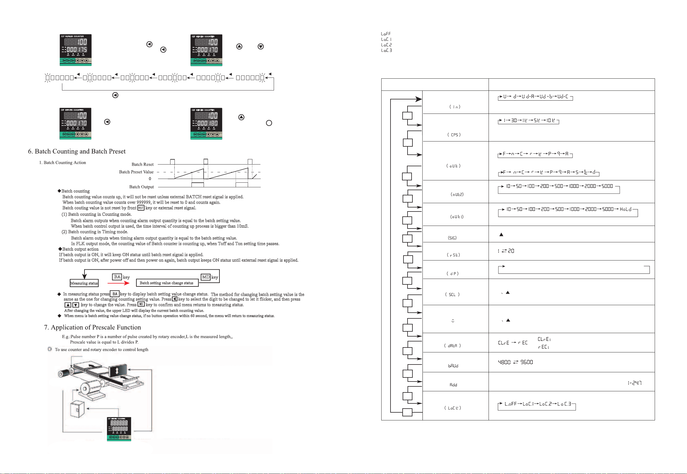
5. Operation Instruction
1. How to change counter setting value (Example: change the setting calue from 175 to 180)
Under Measuring Status, press Key to enter
into Setting Value modify status, Press Key
again m choose digit 5 and let it flickers
Press Key or Key 5 times,
change the digit from “5” to “0”
Under Measuring Status, press Key to enter into Setting Value Modify Status, the flicking digit is from right to left circularly
Press Key again, choose digit “7”
and let it flicker
Press Key for one time, change
Digit “7” to “8”, Press Key for
confirmation and return back to measuring
status
Set 0.069 of prescale value at prescale value set mode
Roller
Encoder
Motor
Cutter
8. Lock Key Setting
Lock Key be used for avoiding mis-operation
9.Setting of Counter Function Modes
( )
MD
→
- - - - - - → - - - - - - →- - - - - - → - - - - - -
MD
MD
MD
MD
MD
MD
MD
MD
MD
MD
MD
Page 04 KKCIE01-A/2-20140318
* * *
( )
( )
MD
MD
( 、▲)
▲
Setting Mode Select setting
Input Type
Max Counting Speed
Output Mode
Time
OUT2 Output
Time
OUT1 Output
Input Logic
Min Reset Time
Decimal Point
Prescale Value
Initial Value
Memory Retention
Baud Rate
Address
Lock Key
Counting Speed means the highest frequency of INA and INB allowed input, if
the setting value is 5K, the error will be existed if the input signal over than 5K.
If the output Mode is S, T and D, then input mode just can choose Ud-A, B, C
※Up Or Down
※Up/Down - A、B、C
Input Mode
Input Mode
Units: ms
Units: ms
▲
or : Choose NPN or PNP input type
Min Signal width of RESET (mm)
▲
▲
Setting range of prescale value is 0.00001--999999
Key: Shift the flickering digit RST Key: Modify prescale value decimal point
Key: Change the Prescale value
▲
▲
Initial Value: display value after Manual or Auto Reset
Key: Shift the flickering digit
Key: Change the Initial value Initial value range: -99999---999999
Power OFF Counting Value Reset
Power OFF Counting Value Save
Communication Baud is 4800 and 9600 can be choosed
Communication Address: Can be setting freely between
(LOCK OFF):Cancel Lock Key Function.
(LOCK LEVEL1):Lock RST Key
(LOCK LEVEL2):Lock and and Key
(LOCK LEVEL3):Lock RST and Lock and and Key
▲
▲
▲
▲
▲
▲
Up Down
F
N
C
R
Up/DownA,B,C
RESET
999999
SV2
SV1
Display
OUT1 Output
OUT2 Output
0
999999
SV2
SV1
0
999999
SV2
SV1
0
999999
SV2
SV1
0
(OUT)
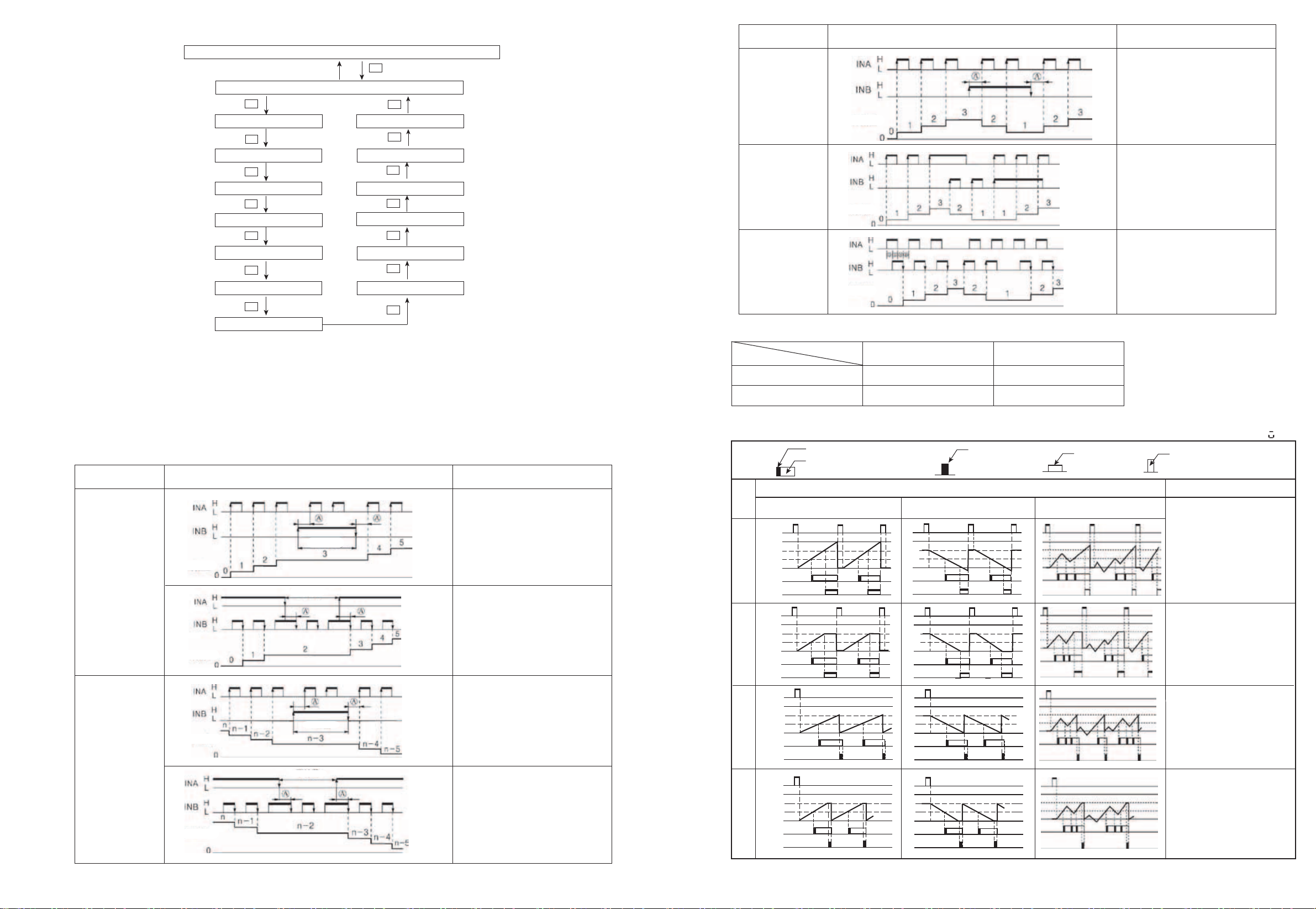
13. Output Operation Mode For Counter
One-shot Output (OUT1 output)
Hold Output
One-shot Output
(OUT2 Output)Hold Output Simultaneous Output
Operation after reached the settingInput Mode
Display will continue to
increase or decrease, output
will be kept to the reset input
Display and output will be
kept to the reset input
Display value will return to the
start status automatically, output
delay will return to the initial status
after reached the setting time.
(Output activity is repeat single
output)
Display value and output will
automatically return to the initial
status after keep to the delay setting
time.
(Output activity is repeat single
output)
RESET
Display
OUT1 Output
OUT2 Output
(OUT)
OUT1 Output
OUT2 Output
(OUT)
RESET
Display
RESET
Display
OUT1 Output
OUT2 Output
(OUT)
Page 06 KKCIE01-A/2-20140318
※Initial Value =0
Ud-a
(Add/ Minus-A)
Order Input
Ud-b
(Add/Minus-B)
Sole Input
Ud-c
Phase Difference Input
Note
Input Type Illustration
INA: Counting Input
INB: Control Input
INB=L; INA pulse input add count
INB=H; INA input pulse minus count
INA input pulse, add count
INB input pulse, minus count
INA before, INB add count
INA delay, INB minus count
Phase difference input
(for rotary encoder)
When using rotary encoder’s A, B ohase output, please connect meter’s INA, INB input terminal, and turn the input mode to Ud-C.
Input Type Voltage Input (PNP) Terminal Input (NPN)
Short Circuit
Open Circuit
H
L
5-30VDC
0-2VDC
Symbol
Counting Value
Counting Value
Counting Value
MD
MD
MD
MD
MD
MD
MD
MD
MD
MD
MD
MD
MD
MD
MD
press for 3 Seconds
Input Mode (IN)
Max Counting Speed (CPS)
Output Mode (OUT)
Output Time (OUT2)
Output Time (OUT1)
Input Logic (SIG)
Min Reset Time (RST)
Decimal Point (dP)
Function Lock Key (LOCK)
Address (ADD)
Baud Rate (BAUD)
Data Storage (DATA)
Initial Value (W)
Prescale Value (SCL)
11. Counter Meter Input Active Mode
U
(Add)
D
(Minus)
※ A:More than Mim Signal Width B:More than half Mim Signal Width
Page 05 KKCIE01-A/2-20140318
3. If the output Mode is S, T and D, then input mode just can choose Ud-A, B, C. If the input mode want to choose UP/DOWN,
then output mode just can chosoe other modes except S,T,D.
4. If the output mode choose D, when counting frequency over than 1Kcps, please choose SSR output.
5. When the Max counting speed is 5Kcps or 10Kcps, if change output mode to D, counting speed will automatically choose 1Kcps.
6. In the mode of function setting,the external input signal can be accepted, after exit, display value and output will be reset automatically.
7. Initial Value over than OUT1 and OUT2 setting value, OUT1 and OUT2 no output
2. If you choose F or N output mode,, when the counting value reached setting value,the output
will be keeped, there is no “OUT2 output time” menu in function setting mode.
1. Under Function Setting Mode. if there is no any operation within 60 seconds, the counter will return back to normal measuring status
10. Active Model Exchange
Measuring Mode (Counting Status)
Note
Input Type Illustration
INA: Counting Input
INB: Control Input
INB=L; INA pulse input add count
INB=H; INA forbid to count
INA: Control Input
INB: Counting Input
INA=H; INB pulse input add count
INA=L; INB forbid to count
INA: Counting Input
INB: Control Input
INB=L; INA pulse input minus count
INB=H; INA forbid to count
INA: Control Input
INB: Counting Input
INA=H; INB pulse input minus count
INA=L; INB forbid to count
No Counting
No Counting
No Counting
Counting Value
Counting Value
Counting Value
Counting Value
No Counting
No Counting
Up/DownA,B,C
S
T
D
SV2
SV1
SV2
SV1
SV2
SV1
Display Value≥Setting Value 1
Display Value≥Setting Value 2
OUT1 and OUT2 meet following
conditions,will keep ON status:
Operation
When display value is smaller than the
preset value “2”, OUT2 keeps OFF
stataus
When display value is smaller than the
preset value “1”, OUT1 keeps ON
stataus
When display value = setting value
OUT1 and OUT2 keeps ON status
When the speed of counter meter setting
to 1kcps, should use SSR output
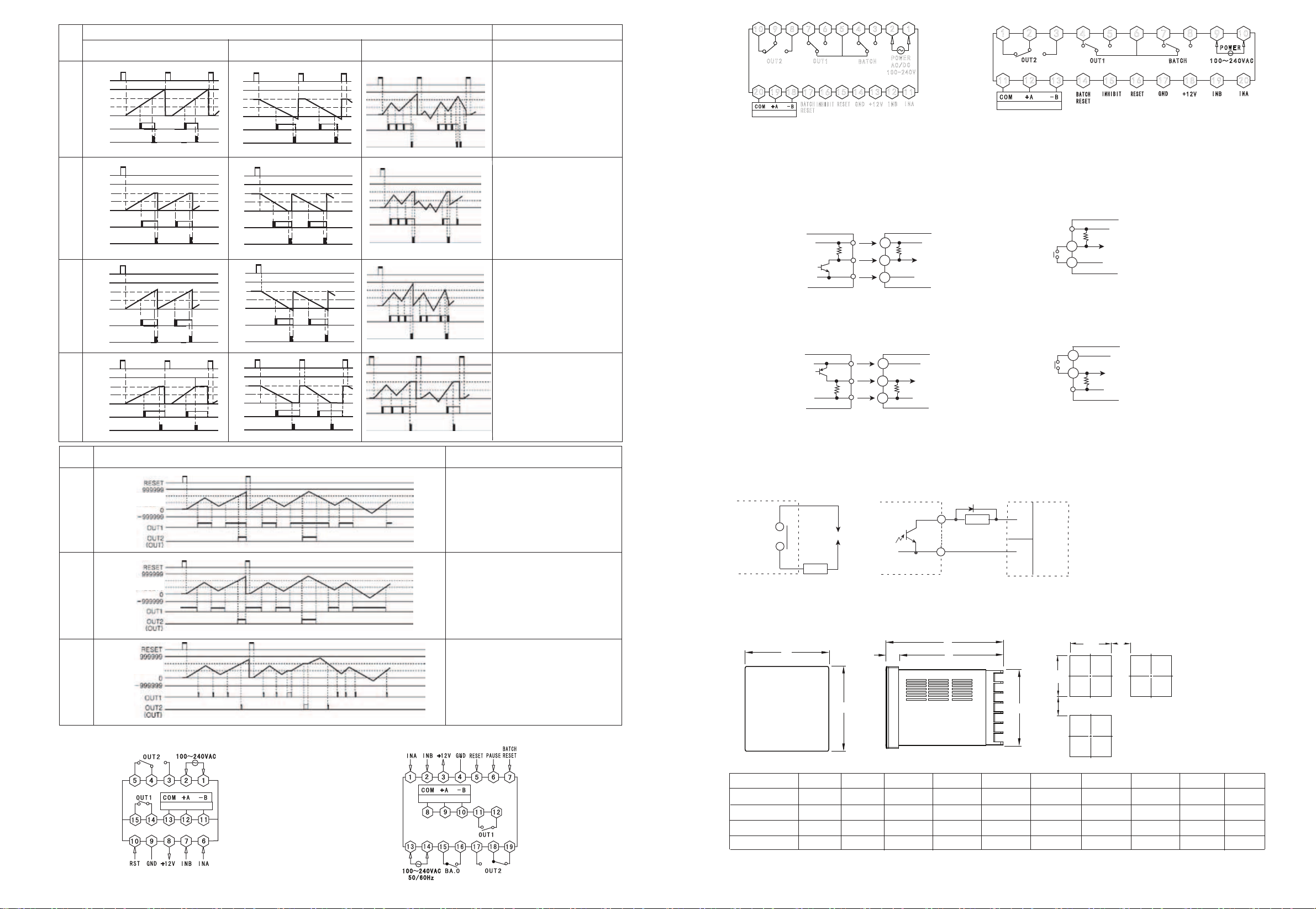
13.Connection Drawing
Up Down
K
P
Q
A
Up/DownA,B,C
999999
SV2
SV1
0
999999
SV2
SV1
0
999999
SV2
SV1
0
999999
SV2
SV1
0
Operation after reached the settingInput Mode
Display value will continus to
increase or decrease until reset
input, output delay will return to
the initial status after reached
the setting time.
(Output activity is repeat single
output)
Display value kept to the delay
time, will display the next cycle.
(In the delay time, the next cycle
counting and timing from initical
status)
(Output activity is repeat single
output)
Display value will continus to
increase or decrease within
output delay time, display value
and output will return to the
initial status after output delay
reached the setting time.
(Output activity is repeat single
output)
Display value and OUT1 output
will be kept to the reset input,
OUT2 output will return to the
initial statusafter reaching the
setting time.
(Output activity is repeat single
output)
RESET
Display
OUT1 Output
OUT2 Output
(OUT)
RESET
Display
OUT1 Output
OUT2 Output
(OUT)
RESET
Display
OUT1 Output
OUT2 Output
(OUT)
RESET
Display
OUT1 Output
OUT2 Output
(OUT)
Page 07 KKCIE01-A/2-20140318
CI7
CI4 RS485
RS485
+12V
5.4kΩ
OV
(CI Series)
Counting Speed: 1 or 30 cps setting (Counter)
+12V
5.4kΩ
OV
(NPN no voltage input) (CISeries)
※
※
+12V
5.4kΩ
OV
+12V
5.4kΩ
OV
(PNPvoltage input) (CI Series)
※
+12V
INA
GND
※
+12V
INA
GND
INA
GND
+12V
INA
Note: If there is any change, please subject to the drawing on the meter!
14. Input Connection
1. Input logic: without voltage input (NPN)
(1). SSR input
Standard sensor: NPN output
Sensor Counter
(2) Terminal Connection
Counter
Inner Circuit
Inner Circuit
2. Input logic : voltage input (PNP)
(1). SSR input
Standard sensor: NPN output
Sensor Counter
(2) Terminal Connection
Counter
Inner Circuit
Inner Circuit
(CI Series)
Counting Speed: 1 or 30 cps setting (Counter)
Load
(DC)
(+)
(-)
15. Output Connection
Relay Output
Timer/Counter
SSR Output
Timer/Counter
Load Power Load
Power
SSR Output:
1. Please use adaptable load and power, SSR output
can not over then ON/OFF, capacity (30VDC, less than100mA)
2. Making sure that the power connected in the right way,
3. When using Inductive load(Relay, etc), Filter circuit(Diode, etc)
must connect to the load ends
Load
Page 08 KKCIE01-A/2-20140318
1
2
3
4
5
6
7
8
9
10
INB
INA
+12V
GND
RESET
INHIBIT
BATCH
RESET
BATCH
OUT1
OUT2
11
12
13
14
15
16
17
18
19
20
AC/DC
POWER
100-240V
CI8
POWER
1 0 0~240 A C0V
1 2 3 4 5 6 7 8 9 10
I N B
INA
+12V
GND
RESET
INHIBIT
BATCH
RESET
BATCH
OUT1
OUT2
11 12 13 14 1 5 1 6 17 18 19 2 0
CI80
CI4:(48*48)
CI7:(72*72)
CI8:(48*96)
CI80:(80*160)
48
72
96
160
Model AH(Min)
G
B C D E F
J
48
72
48
80
97.5
97.5
97.5
96
3
3
3
13
94.5
94.5
94.5
83
45.5
67.5
90
76
25
25
25
30
45.5
67.5
45
155.5
45
67
44.5
155
K
(Min)
25
25
25
30
A
B
C
E
D
F
G
K
J+0.5
-0
+0.5
-0 H
RS485
RS485
16. Dimension
Panel Size Side Face Size Mounting Size

Page 09 KKCIE01-A/2-20140318
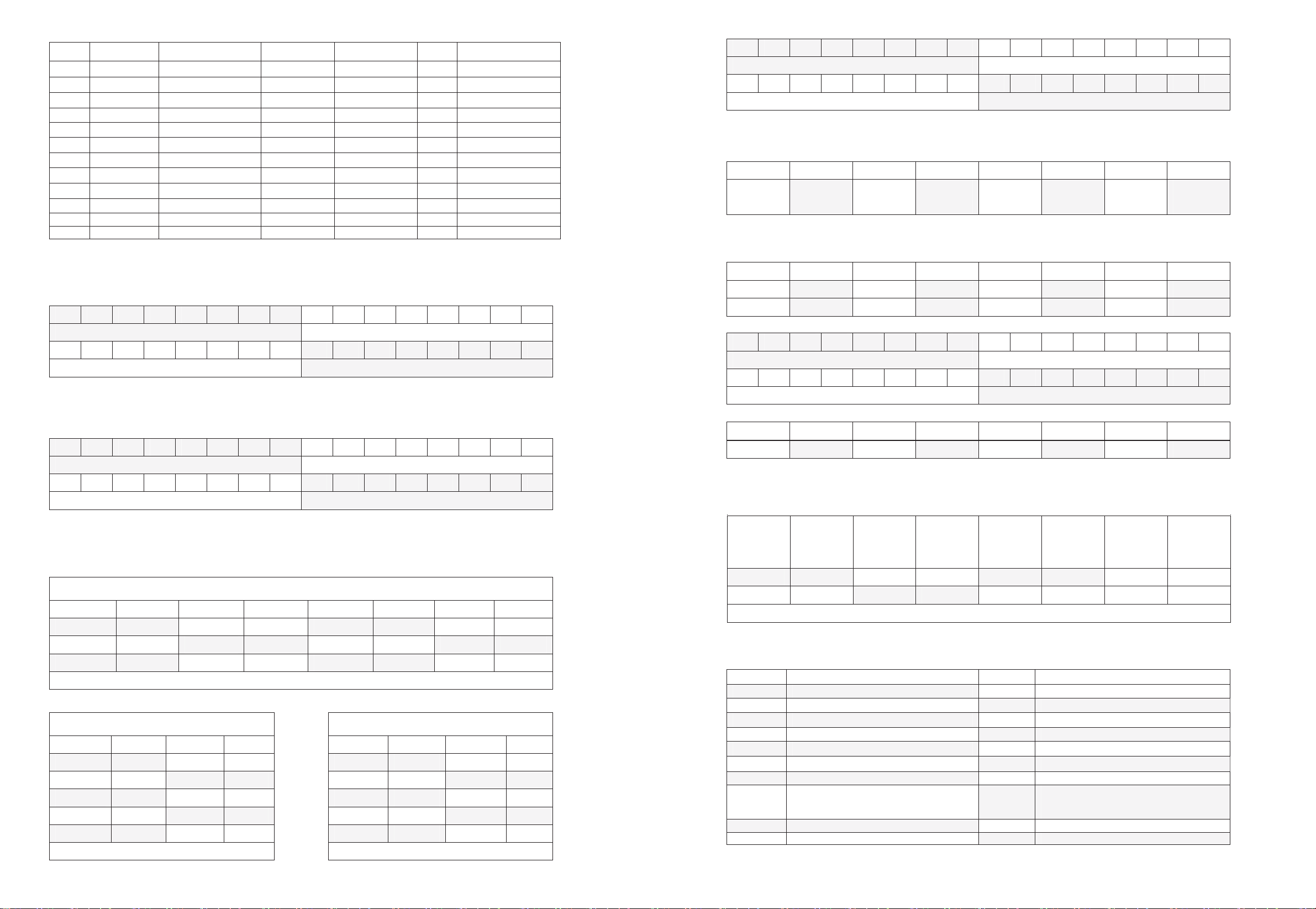
Counter Meter Communication Protocol
1. Type and Format of Communication Data
This series counter meter are using asynchronous serial transmission communication interface, the TTL
accompany to standard RS485 requirement. Communication compatible with standard Modbus RTU
transmission, Start bit of frame data format is one bit, 8 datat bit, un-checked, one stop bit. Baud rate of
communication transmission data is 4800 ir 9600 Bit/S which can set freely.
Frame Data Format
Start Bit Data Bit Checkout Bit Stop Bit
1oN81
2. Transmission Process of Communication Message
When the Communication order of Host computer be send to follow computer, the follow computer
which with the same address of Host computer would accept this order. For example, when CRC check and
order format are both without any question, then the follow computer will carry out this operation and send the
result back to Host computer.
2-1 Meter Address (One Bit)
Meter address be inclused in the message’s address zone, the range of address is 1-247. Host computer
will choose the follow computer whose meter address can accompany to Host computer order’s address
zone.When the follow computer send back the result, it will put it’s own meter address into the
return-message’s address zone, then that the Host computer can recognize which follow computer give reply.
(Meter address is Unique)
2-2 Function Code (One Bit)
Function code be included into the function code zone. Host computer send function code, which can
instruct the operation, to follow computers, When the follow computer make a reply, function code will tell the
host computer whether there is anything wrong.
Function Code Definition
noitarepOnoitinifeDedoCnoitcnuF
0x03 Read Register Read single or many register’s data
0x10 Multi-write Register Put numerous data into register
2-3 Data Area Which be included into the message’s data zone, length of data will be different
according to the function code.
3.Host Computer Order Format and Follow Computer Return Message Format
3-1 Multi-read Register
For Example:Host Computer send out read order, register data of follow computer OUT2 alarm value
Order
format Host Computer Send Out Order Message
Format Follow Computer Return Message
ADD
Zone Meter Address 0X01 ADD
Zone Meter Address 0X01
Function
Zone Function Code 0X03 Function
Zone Function Code 0X03
40X0rebmuNtiBataD00X0tiBhgiH
Start Register
ADD 0CX01tiBwoL50X0tiBwoL
A5X02tiBwoL00X0tiBhgiH
Data Zone
Read Register
Quantity Low Bit 0X01
Data
Zone OUT2
register data
High Bit 1 0XFB
43X02tiBhgiH49X0tiBwoL
Error
Check
Zone
CRC Check
Code 4AX0tiBwoLB0X0tiBhgiH
Error
Check
Zone
CRC Check
Code High Bit 0XC7
Page 10 KKCIE01-A/2-20140318
Note: This is just an example for read single register data’s order and return format, when it is need to
read many registers at the same time, you just should know the register’s start address and the number of read
register. When return the data, low bit data will always before then high bit data.
3-2 Multi-write Register
For Example: Host computer send out order, write data 1000.000 into follow computer, register of OUT2
alarm value.
Order
format Host Computer Send Out Order Message
Format Follow Computer Return Message
ADD
Zone Meter Address 0X01 Meter
Address ADD Zone 0X01
Function
Zone Function Code 0X10 Function
Code Function Zone 0X10
High
Bit 00X0tiBhgiH00X0
Start Register
ADD
Low Bit 0X05
Start
Register
ADD Low BIt 0X05
High
Bit 00X0tiBhgiH00X0
Write Register
Quantity
Low Bit 0X01
Data
Zone Write
Register
Quantity Low BIt 0X01
11X0tiBwoL40X0tibatadetirW
Low Bit
1 0X40
Error
Check
Zone
CRC Check
Code High Bit 0XC8
Low Bit
2
High
Bit 1 0X0F
Data Zone
Data which will
be write into
OUT2 register
Hihg
Bit 2 0X00
Low Bit 0X83
Error
Check
Zone
CRC Check
Code High
Bit 0X87
4. Communication Error Processing
When the meter check out the error which is not CRC check code error, then it will return error
information to Host computer, Follow computer will return those information—function code high bit 1, meter
address, error code—back to host computer.
4-1 Format of Error Code which be returned from Follow Computer
ADD Code Function Code Error Code CRC Check Code
Low Bit
CRC Check Code
High Bit
One Bit One Bit One Bit One Bit One Bit
4-2 Error Code
0X01 Function Code
Illegality The meter didn’t recognize the function code
0X02 Register Add
Illegality Receiving register address exceed the range of register’s address
0X03 Register quantity
Illegality Receiving register quantity exceed the range of register’s quantity
0X04 Data value Illegality Receiving data value exceed the range of register’s data value
Page 11 KKCIE01-A/2-20140318
5. Meter’s Reference Address
No. Register ADD Register Name Data Type Measuring Range Nature Note
0 0x0001 Value PV long ----- R Reserve 3 decimal point
1 0x0002 Batch Value BV Unsigned long ----- R
2 0x0003 Alarm Status Unsigned long -----
R
3 0x0004 OUT1 Alarm (PS1) Unsigned long 1~999999000 R/W
Reserve 3 decimal point
4 0x0005 OUT2Alarm (PS2) Unsigned long 1~999999000 R/W Reserve 3 decimal point
5 0x0006 BA.Oalarm (BA.S) Unsigned long 1~999999 R/W
6 0x0007 Scale Factor SCL Unsigned long 0.00001-9999.99 R/W
Reserve 5 decimal point
7 0x0008 Initial Value W long -99999-999999 R/W Reserve 3 decimal point
8 0x0009 Meter’s Status 1 Unsigned long ----- R/W
9 0x000A Meter’s Status 2 Unsigned long ----- R/W
10 0x000B Meter’s Status 3 Unsigned long ----- R/W
11 0x000C Meter’s Status 4 Unsigned long ----- R/W
* PV, PS1, PS2 will acquiesce in 3 decimal point. Actual data=return data or write in data/1000. If Read PV
register return data=1, the the actual PV value=0.001. At the same time, when write 10000000 into PS2 register,
then the actual OUT2setting value (PS2)=1000.0000.
6. Alarm Status (Add:0x0003)
Bit31 Bit30 Bit29 Bit28 Bit27 Bit26 Bit25 Bit24 Bit23 Bit22 Bit21 Bit20 Bit19 Bit18 Bit17 Bit16
lobmyStuptuOmralAO.ABevreseR
Bit15 Bit14 Bit13 Bit12 Bit11 Bit10 Bit9 Bit8 Bit7 Bit6 Bit5 Bit4 Bit3 Bit2 Bit1 Bit0
OUT2 Alarm Output Symbol OUT1 Alarm Output Symbol
6-1、Bit0-Bit7 OUT1 Alarm Output Symbol:0x00:OUT1 Alarm No Output,0x01:OUT1 Alarm and Output。
6-2、Bit8-Bit15 OUT2 Alarm Output Symbol:0x00:OUT2 Alarm No Output,0x01:OUT2 Alarm and Output。
6-3、Bit16-Bit23 BA.O Alarm Output Symbol:0x00:BA.O Alarm No Output,0x01:BA.O Alarm and Output。
7. Register of Meter Status (Add: 0x0009)
Bit31 Bit30 Bit29 Bit28 Bit27 Bit26 Bit25 Bit24 Bit23 Bit22 Bit21 Bit20 Bit19 Bit18 Bit17 Bit16
OUT2 Output delay time setting menu OUT1 Output delay time setting menu
Bit15 Bit14 Bit13 Bit12 Bit11 Bit10 Bit9 Bit8 Bit7 Bit6 Bit5 Bit4 Bit3 Bit2 Bit1 Bit0
OUT Output type setting value SIG Input terminal SSR choosing
7-1、Bit0-Bit7:SIG Input terminal SSR choosing(choosing range: 0x00-0x01)。
Bit0-Bit7=0x00:NPN Input mode,Meter’s signal input terminal will connect with 12V auxiliary power supply through
inner 7.4K resistance.
Bit0-Bit7=0x01:PNPinput mode, Meter’s signal input terminal will connect with public earth wire through inner5.4K resistance.
7-2、Bit8-Bit15:OUT Meter’s output mode choosing(Choosing range according to current status)。
Bit8—Bit15 Output mode
Bit8—Bit15 Output mode Bit8—Bit15 Output mode Bit8—Bit15 Output mode Bit8—Bit15 Output mode
0x00 F 0x01 N 0x02 C 0x03 R
0x04 K 0x05 P 0x06 Q 0x07 A
0x08 S 0x09 T 0x0a D
Note:Before you are changing the output mode to D , please sure that the count frequency CP≤1KHZ, otherwise it will return the error code!
7-3、Bit16—Bit31:OUT1、OUT2 Alarm Output delay time choosing menu (Choosing range 0x00-0x08).
Bit16—Bit23Corresponding OUT1output delay time Bit24—Bit31Corresponding OUT2output delay time
Bit16—Bit23 Delay time Bit16—Bit23 Delay time Bit24—Bit31 Delay time Bit24—Bit31 Delaytime
0x00 10mS 0x01 50mS 0x00 10mS 0x01 50mS
0x02 100mS 0x03 Sm00120x0Sm002 0x03 200mS
0x04 500mS 0x05 1000mS 0x04 500mS 0x05 1000mS
0x06 2000mS 0x07 Sm000260x0Sm0005 0x07 5000mS
0x08 HOLD
Note::Bit16—Bit23 choosing range(0-8)
Note :Bit24—Bit31Choosing range(0-7)
Page 12 KKCIE01-A/2-20140318
8. Register 2 of Meter Status (Add:0x000A)
Bit31 Bit30 Bit29 Bit28 Bit27 Bit26 Bit25 Bit24 Bit23 Bit22 Bit21 Bit20 Bit19 Bit18 Bit17 Bit16
oPATADesoohCedoMtupninI wer OFF data preserve choose
Bit15 Bit14 Bit13 Bit12 Bit11 Bit10 Bit9 Bit8 Bit7 Bit6 Bit5 Bit4 Bit3 Bit2 Bit1 Bit0
DPDecimal point display choose RSTInput control signal valid length of pulse choose
8-1、Bit0-Bit7:RST Input control signal valid length of pulse choose(Range 0x00-0x01)。
Bit0-Bit7=0x00:Input control signal valid length of pulse is 20mS。
Bit0-Bit7=0x01:Input control signal valid length of pulse is 1mS。
8-2、Bit8-Bi15:DPDecimal point display choose(Range 0x00-0x03)。
Bit8—Bit15 Decimal Point Bit8—Bit15 Decimal Point Bit8—Bit15 Decimal Point Bit8—Bit15 Decimal Point
0x00
No Decimal
Point 0x01
One Decimal
Point 0x02
Two Decimal
Point 0x03
Three Decimal
Point
8-3、Bit16-Bit23:DATA Power OFF data preserve choose(Range 0x00-0x01)
Bit16-Bit23=0x00:Count comes to Zero when Power OFF.
Bit16-Bit23=0x01:Count value will be preserved when power off and will recount from this value from next time power on!
8-4、Bit24-Bit31:INInput mode choose(Range 0x00-0x04)。
Bit24—Bit31 Input Mode Bit24—Bit31 Input Mode Bit24—Bit31 Input Mode Bit24—Bit31 Input Mode
0x00 U 0x01 D 0x02 UD-A 0x03 UD-B
0x04 UD-C
9. Register 3 of Meter Status (Add:0x000B)
Bit31 Bit30 Bit29 Bit28 Bit27 Bit26 Bit25 Bit24 Bit23 Bit22 Bit21 Bit20 Bit19 Bit18 Bit17 Bit16
CPS Count Frequency UPPer limit Choose Menu ADD Meter Communication ADD Setting Menu
Bit15 Bit14 Bit13 Bit12 Bit11 Bit10 Bit9 Bit8 Bit7 Bit6 Bit5 Bit4 Bit3 Bit2 Bit1 Bit0
BAUD Communication Baud Rate Setting Menu LOCK Button Level Setting Menu
9-1、Bit0-Bit7:LOCK Button Level Setting Menu(Range0x00-0x03)。
Bit8—Bit15 Level Bit8—Bit15 Level Bit8—Bit15 Level Bit8—Bit15 Level
0x00 L.OFF 0x01 LOC.1 0x02 LOC.2 0x03 LOC.3
9-2、Bit8-Bit15:BAUD Communication Baud Rate Setting Menu(Range 0x00-0x01)。
Bit8-Bit15=0x00:Baud Rate=9600Bit/S(9600)。
Bit8-Bit15=0x01:Baud Rate=4800Bit/S(4800)。
9-3、Bit16-Bit23:ADD Meter Communication ADD Setting Menu(Range 0x01-0xf7)。
9-4、Bit24-Bit31:CPS Count Frequency UPPer limit Choose Menu(range decide by output mode)。
Bit24—Bit31
Frequency
Uppper
Limit
Bit24—Bit31
Frequency
Uppper
Limit
Bit24—Bit31
Frequency
Uppper
Limit
Bit24—Bit31
Frequency
Uppper
Limit
0x00 1HZ 0x01 30HZ 0x02 1KHZ 0x03 5KHZ
0x04 10KHZ
Note: Output mode is D mode. Bit24-Bit31, choosing range (0x00—0x02), otherwise choosing range is (0x00—0x04)
10. Data Error Code
10-1. Data error code, under the condition of order format, meter address, function code and CRC check code are all correct,
when the host computer write error data into the follow computer, follow computer will return back the error code which is in
corresponding to the host computer, detail as follows:
Error Code Definition Error Code Definition
0x14 OUT1 Alarm Value(PS1)Error 0x15 OUT2 Alarm Value(PS2)Error
0x16 BA.O Alarm Value (BA.S) Error 0x17 SCL Coefficient Error
0x18 rorrEesoohCcigoLtupnIGIS91x0rorrEeulaVlaitinIW
0x1A OUT Output Mode Choose Error 0x1B OUT1 Output Delay Time Choose Error
0x1C OUT2 Output Delay Time Choose Error 0x1D RST Min Reset time Choose Error
0x1E DP Decimal Point Choose Error 0x1F DATA Reserve Count Value Choose Error
0x20 IN Input Mode Choose Error 0x21 LOCK Button Choose Error
0x22 BAUD Communication Baud Rate Choose
Error 0x23 ADD Meter Communication Address Setting
Error
0x24 CPS Max. Count Speed Choose Error 0x25
0x26 0x27
Announcement:
When write the data into the meter through communication port, the write-in time of each storage element is
limited, CI series counter meter
than the provide, it can cause the damage on meter’s storage element!
can accept at least 100 thousand times write-in. If write-in time exceed
This manual suits for next models
5
Other Toky Cash Counter manuals


Popular Cash Counter manuals by other brands

Triton
Triton 9750 Series Quick reference guide

Met One Instruments
Met One Instruments AEROCET 831 manual

CS Instruments
CS Instruments VA 520 instruction manual

Omron
Omron CS1 - Operation manual

DIEBOLD NIXDORF
DIEBOLD NIXDORF DN Series 100D FL operating manual

Parametric
Parametric TCR-EU868 quick start guide

Lightning Protection International
Lightning Protection International LSR2 Technical data sheet

Eaton
Eaton Durant Ambassador 57600-400 Installation and operation manual

ascon
ascon TC 32 user manual

Omron
Omron HJ-325 instruction manual

Spectrum Techniques
Spectrum Techniques ST365 Technical manual

Cashmaster
Cashmaster One Pro user manual


