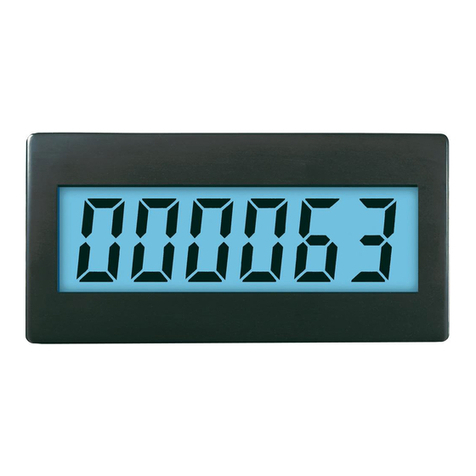
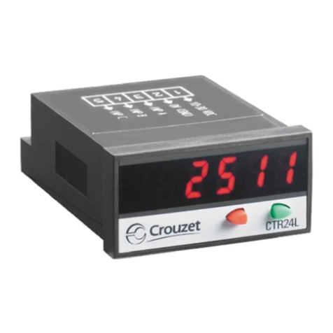
Toky CA-X Series User manual

Features:
⊙Dual line 6 digits LED display
⊙Optional dimension: 48W×48H、96W×48H、72W×72H
⊙Can work with incremental rotary encoder, carry out up and down
counting.
⊙One loop relay output.
⊙Manual reset, auto reset, key lock function, power failure memory
function.
⊙Settable counting coefficient, NPN or PNP input selectable.
⊙Widely applied to the industries relevant to timber machining, food
machinery, packing machinery, steel machining, etc.
V. Connection Diagrams
1
IV. Dimension & Panel Cutout
Panel Size Side Size Cutout Size
CA4:(48×48)
CA7:(72×72)
CA8:(48×96)
48
72
96
Classification Panel dimension Panel cutout
AH(Min)
G
B C D E F J
48
72
48
97.5
97.5
97.5
6.5
9.0
9.0
91.0
88.5
88.5
45.5
67.5
92
25
25
25
45.5
67.5
45
45
67
44.5
K(Min)
25
25
25
Remark Unit:(mm) tolerance +0.5% (unless there is special
specific illustration)
A
B
C
ED
F
G
K
J+0.5
-0
+0.5
-0
H
Note: If there is any change, please subject to the drawing on the meter.
CA8
CA4
10 9 8 7 6
+12V
AC/DC
100~240V
OUT
INB INARST GND
45 3 2 1
CA7
AC/DC
100~240V
OUT
INA INB +12V RESET INHIBITGND
21 3 4 5 6
1413 17 18 19
OUT AC/DC
100~240V
INHIBIT RESET GND INAINB+12V
21 3 9 10
15 16 17 18 19 20
II. Technical Parameter
AC/DC 100~240V 50/60Hz
≤4W
AC 250V/3A
DC 12V±5V(≤25mA)
≥20MΩ
AC 2kV
Power:3000Vp-p、I/0 terminal:1000Vp-p
Power Supply
Total Power Consumption
Relay Capacity
Output Power
Insulation Resistance
Insulation Strength
Anti-interference
Input Signal (sine wave,
square wave)
Counting Input Speed
Counting Range
Delay Time
Coefficient Setting Range
External Signal
Signal Level: Hight:3~30V Low:0~2V
≤1/30/300/5000Hz (4 speed
selectable)
-199999~999999
0.01~499.99s
0.00001~999999
External reset frequency
1、20ms selectable
CA-X Series Digital Counter
KKCAX-A01C-20180120
Digital Counter
CA-X series
Thank you for purchasing TOKY products. Please
read the instruction manual carefully before using this
product, and use the product correctly. Also, please keep
this instruction manual where you can view it any time.
TOKY ELECTRICAL CO., LTD.
No.8, Minke West Road, Shiqi District,
Zhongshan City,
Guangdong Province,
China
TEL: +86-760-23371807
http://www.toky.com.cn
INSTRUCTION MANUAL
Note: If there is no operation for long time, meter will automatically
return back to measuring state (set parameter is not saved.)
SET
(1) Menu key: press it 3 sec to enter or exit setup mode.
(2) Confirm key: confirm and save the modified set value.
Up key
RST Reset key
In modification state, press it to increase set value.
(1) In operation mode or setup mode, press it to
activate the set value modification.
(2) In modification state, press it to move set
value row.
In operation mode, press it to reset PV.
Name Content
Shift key
Set key
III. Panel Illustration
5
SET RST
OUT SV
PV
PRESENT VALUE
(1) Display present value in
operation mode
(2) Display parameter code
in setup mode
Operation indicator
OUT: Turns on
during output
operation
SET VALUE
(1) Display set value in
operation mode
(2) Display parameter set
value in setup mode
UP
RESET
SET
SHIFT
Communication
Display digits
Version
0
6
8
X-A
Size
6 digits display
No communication
RS485 communication
Version A
Alarm RB 1 relay output
FAC/DC 24V
Power
voltage
- AC/DC 100~240V
896(W) X 48(H) X 88.5(D) mm
772(W) X 72(H) X 88.5(D) mm
I. Suffix Code
Code Content
CA
4
Model
□ □-□CA-X series digital counter
48(W) X 48(H) X 91(D) mm
X-□□ □

VI. Operation process
2
Operation Mode
Enter correct password, press SET key to enter Setup Mode.
Press SET key
Press SET key
Press SET key
Press SET key
Press SET key
Press SET key
Press SET key
Press SET key
Setup mode ( key: shift digit, key: modify, SET key: confim)
Input logic
Setting range:NPN、PNP
Default = NPN
Output mode
Setting range:F、N、
C(default)、R、K、P、
Q、A、M
Counting speed
Setting range(unit: Hz):
1、30、1000、5000(default)
Menu password
Have to input 4 digits password correctly, otherwise the Setting Menu
cannot be accessed (default value=0000)
Version
Menu password setting
Setting range:0000~9999
Default value = 0000
Input type
Setting range:U、D、
UD-A(default)、UD-B、
UD-C
Press SET key
Press SET
key
Press SET
key
Press SET
key
Press SET > 3 sec
Input wrong password
for 3 times
Decimal point
Setting range:0
~
3
Default value = 0(no
decimal point)
Prescale value
Setting range:
0.00001~999999
Default value = 1.00000
OUT output delay setting
Setting range: 0.01
~499.99
s
Default value = 1.00s
Data storage setting
Reset counting value after power failure
Remain counting value after power failure (default)
Press SET key 3 sec to confirm and exit
Min reset time
Setting range:1、20ms
Default value = 1ms
= No lock (default)
= Lock RST key
= Lock 、key
= Lock 、、RST key
Key lock
Bulge
POWER +12V
INA CA Counter
GND
OUT
GND
Proximity
sensor
Wheel M
POWER
A
B
GND
CA Counter
+12V
INA
INB
GND
Wheel
MRotary
encoder
Proximity sensor input Rotary encoder input

No counting
3
U
(Add)
D
(Minus)
Input type Illustration Note
※A :> minimum signal width B :> 1/2 minimum signal width
VII. Input Mode
Symbol Input Type
H
L
Voltage Input (PNP)
DC 5-30V
DC 0-2V
Terminal Input (NPN)
Short Circuit
Open Circuit
UD-A
(Add/ Minus-A)
Order Input
UD-B
(Add/Minus-B)
Sole Input
UD-C
Phase Difference
Input
No counting
No counting
INA: Counting Input
INB: Control Input
INB=L: INA pulse input add count
INB=H: INA forbid to count
INA: Counting Input
INB: Control Input
INB=L: INA pulse input minus count
INB=H: INA forbid to count
INA: Counting Input
INB: Control Input
INB=L: INA pulse input add count
INB=H: INA pulse input minus
counting
INA: Control Input
INB: Counting Input
INA=H: INB pulse input add count
INA=L: INB forbid to count
INA: Control Input
INB: Counting Input
INA=H: INB pulse input minus count
INA=L: INB forbid to count
INA input pulse, add count
INB input pulse, minus count
No counting
Counting Value
Counting Value
Counting Value
Counting Value
Counting Value
Counting Value
Counting Value
※When using rotary encoder’s A, B phase output, please connect meter’s INA, INB input terminal, and set the input mode as UD-C.
INA before, INB add count
INA delay, INB minus count
Phase difference input (for rotary
encoder)

4
K
P
Q
A0
0
0
0
Input Mode
Up Down
F
N
C
R
VIII. Output Mode
Up/DownA,B,C
One-shot Output Hold Output Simultaneous Output
0
0
0
Reset
999999
SV
Display
OUT output
Reset
999999
SV
Display
OUT output
Reset
999999
SV
Display
OUT output
Reset
999999
SV
Display
OUT output
Reset
999999
SV
Display
OUT output
Reset
999999
SV
Display
OUT output
Reset
999999
SV
Display
OUT output
Reset
999999
SV
Display
OUT output
0
Operation after reached the SV
M
SV
SV
SV
Reset
999999
Display
OUT output
SV
SV
SV
0
SV
0
Display will continue to
increase or decrease, output
will be kept until the reset input
Display and output will be
kept until the reset input
Display value will return to the
start status automatically,
output delay will return to the
initial status after reached the
setting time.
(Output activity is repeat single
output)
Display value and output will
automatically return to the
initial status after keep to the
delay setting time.
(Output activity is repeat single
output)
Display value will continus to
increase or decrease until reset
input, output delay will return to
the initial status after reached
the setting time.
(Output activity is repeat single
output)
Display value be kept until the
delay time, will display the next
cycle. (In the delay time, the
next cycle counting and timing
from initical status)
(Output activity is repeat single
output)
Display value will continus to
increase or decrease within
output delay time, display
value and output will return to
the initial status after output
delay reached the setting time.
(Output activity is repeat single
output)
Display value will be kept until
the reset input, OUT output will
return to the initial status after
reaching the setting time.
(Output activity is repeat single
output)
When display value=an integral
multiple of SV, OUT output will
automatically return to the initial
status after reaching the setting
time. Display value will keep
accumulating, when display
value is greater than the
maximum display value, it will
automatically overflow.
Other Toky Cash Counter manuals
Popular Cash Counter manuals by other brands
Setra Systems
Setra Systems 3000 Series user manual
NCR
NCR SelfServ 84 Walk-Up manual

Steinberg Systems
Steinberg Systems SBS-CC-500 user manual

Precision Digital Corporation
Precision Digital Corporation Vantageview PD6720 manual
GSR Laser Tools
GSR Laser Tools GT1000C manual
Innovative Instruments & Controls
Innovative Instruments & Controls Cx-428 User's operating manual


