TOLSEN TOOLS 79988 User manual
79988
QUIET INVERTER GENERATOR
INSTRUCTION MANUAL
SAVE THIS MANUAL !
You will need this manual for safety instructions, operating procedures and warranty.
Put it and the original sales receipt in a safe dry place for future reference.
4000W
energy saving
Cleaner power
protectyour electric appliances
<3%

2 SPECIFICATIONS
SPECIFICATIONS
Item No.:79988(CE)
Generator
Output
230 VAC, 50 Hz, 4000W, 1 Phase;
12 VDC 8.3 A; 3500 Running Was; 4000
Maximum Starng Was
Receptacles
2x VDE PLUG (Earthing);
1 x 12 V DC Connecon terminal
2XUSB Point port(5v 1A/2.1A)
Displacement 225cc
Engine Type Horizontal Single Cylinder 4-stroke, OHV
Cooling System Forced air cooled
Fuel
Type 87+ octane, stabilizer-treated unleaded
gasoline
Capacity 12.5L
Engine Oil
Type SAE
10W-30
Capacity 600ml
Run Time @ 50% Load with full tank
8h
Bore x Stroke 58mm x 70mm
The engine's emission control system complies with Eu 5 emissions.
3SPECIFICATIONS
Symbol Definitions
Important safety instructions
Symbol
property or Statement
RPM
Revolutions Per Minute
Hp
Horsepower
WARNING marking concerning Risk of Eye Injury.
Wear ANSI-approved safety goggles with side
shields.
Read the manual before set -up and/or use.
WARNING marking concerning Risk of Hearing Loss.
Wear hearing protection.
WARNING marking concerning Risk of Respiratory
Injury. Operate engine OUTSIDE and far away from
windows, doors, and vents.
WARNING marking concerning Risk of Fire while
handling fuel. Do not smoke while handling fuel.
WARNING marking concerning Risk of Fire. Do not
refuel while operating. Keep flammable objects
away from engine.
Warning! Read all instructions. Failure to follow all instructions listed below may result in fire,
serious injury and/or DEATH. The warnings and precautions discussed in this manual cannot cover all
possible conditions and situations that may occur. It must be understood by the operator that common
sense and caution are factors which cannot be built into this product, but must be supplied by the
operator.
SAVE THESE INSTRUCTIONS

Setup precautions
Operating precautions
IMPORTANT SAFETY INFORMATION
4 SAFETY
1. Gasoline fuel and fumes are flammable, and potentially explosive. Use proper fuel storage and handling
procedures. Do not store fuel or other flammable materials nearby.
2. Have multiple ABC class fire extinguishers nearby.
3. Operation of this equipment may create sparks that can start fires around dry vegetation. A spark arrestor
may be required. The operator should contact local fire agencies for laws or regulations relating to fire
prevention requirements.
4. Set up and use only on a flat, level, well-ventilated surface.
5. All connections and conduits from the Generator to the load must only be installed by trained and
licensed electricians.
6. Connections for standby power to a building electrical system must be made by a qualified electrician.
The connection must isolate the Generator power from utility power, and must comply with all applicable
laws and electrical codes.
7. Wear ANSI-approved safety goggles, heavy-duty work gloves, and dust mask/respirator during set up.
8. Use only lubricants and fuel recommended in the Specifications chart of this manual.
9. Improper connections to a building electrical system can allow electrical current from the Generator to
backfeed into the utility lines. Such backfeed may electrocute utility company workers or others who
contact the lines during a power outage, and the Generator may explode, burn, or cause fires when
utility power is restored. Consult the utility company and a qualified electrician if intending to use the
Generator for back up power.
10. Do not operate the Generator before grounding. The Generator must be earth-grounded in accordance
with all relevant electrical codes and standards before operation.
1. CARBON MONOXIDE HAZARD using a generator indoors CAN KILL you in MINTES. Generator
exhaust contains carbon monoxide. This is a poison you cannot see or smell.
NEVER use inside a home or garage, EVEN IF doors and windows are open.
Only use OUTSIDE and far away from
windows, doors, and vents.

2. Never use a generator indoors, including in garages, basements, crawl spaces and sheds. Opening doors
and windows or using fans will NOT prevent carbon monoxide build up in the home.
3. When using generators, keep them outdoors and far away from open doors, windows, and vents to avoid
toxic levels of carbon monoxide from building up indoors.
4. If you start to feel sick, dizzy, or weak while using a generator, get to fresh air right away. The carbon
monoxide from generators can quickly lead to full incapacitation and death.
5. Keep children away from the equipment, especially while it is operating.
6. Keep all spectators at least six feet from the engine during operation.
7. Fire Hazard! Do not fill gas tank while engine is running. Do not operate if gasoline has been spilled.
Clean spilled gasoline before starting engine. Do not operate near pilot light or open flame.
8. Do not touch engine during use. Let engine cool down aer use.
9. Never store fuel or other flammable materials near the engine.
10. If the plugged in product operates abnormally or unusually slow, immediately stop using the generator
as a power source. Read and adhere to the instruction manual of the product to be powered to make sure
that it can be safely and efficiently powered by a portable generator.
11. Before connecting an appliance or power cord to the generator: Make sure that it is in good working
order. Faulty appliances or power cords can create a potential for electrical shock.
12. Do not exceed the running wattage of the generator. Make sure that the total electrical rating of the all of
the tools or appliances plugged into the generator at the same time does not exceed that of the
generator. Check that the startup surge will not be beyond the limit of the generator.
13. Avoid substantially overloading which will trip the circuit breaker. Slightly overloading the generator
may not trip the circuit breaker, but will lead to premature generator failure.
14. Do not attempt to connect or disconnect load connections while standing in water, or on wet or soggy
ground.
15. Do not touch electrically energized parts of the generator and interconnecting cables or conductors with
any part of the body, or with any non-insulated conductive object.
16. Connect the generator only to a load that is compatible with the electrical characteristics and running
wattage of the generator.
17. Insulate all connections and disconnected wires.
18. Guard against electric shock. Prevent body contact with grounded surfaces such as pipes, radiators,
ranges, and refrigerators.
19. Only use a suitable means of transport and liing devices with sufficient weight bearing capacity when
transporting the generator.
20. Secure the generator on transport vehicles to prevent it from rolling, slipping, and tilting.
21. Industrial applications must follow OSHA requirements.
22. Do not leave the generator unattended when it is running. Turn off the generator (and remove safety
keys, if available) before leaving the work area.
23. The generator can produce high noise levels. Prolonged exposure to noise levels above 85 dBA is
hazardous to hearing. Wear ear protection when operating the generator or when working nearby while
it is operating.
SAFETY 5

24. Keep access doors on enclosures locked.
25. Wear safety glasses and hearing protection during use.
26. People with pacemakers should consult their physician(s) before use. Electromagnetic fields in close
proximity to a heart pacemaker could cause pacemaker interference or pacemaker failure. Caution is
necessary when near the engine’s magneto or recoil starter.
27. Use only accessories that are recommended by Harbor Freight Tools for your model. Accessories that
may be suitable for one piece of equipment may become hazardous when used on another piece of
equipment.
28. Do not operate in explosive atmospheres, such as in the presence of flammable liquids, gases, or dust.
Gasoline-powered engines may ignite the dust or fumes.
29. Stay alert, watch what you are doing and use common sense when operating this generator. Do not use
while tired or under the influence of drugs, alcohol or medication.
30. Dress properly. Do not wear loose clothing or jewelry. Keep hair, clothing and gloves away from moving
parts. Loose clothes, jewelry or long hair can be caught in moving parts.
31. Parts, especially exhaust system components, get very hot during use. Stay clear of hot parts.
32. Do not cover the generator during operation.
33. Keep the generator and surrounding area clean at all times.
34. Do not smoke, or allow sparks, flames, or other sources of ignition around the equipment, especially
when refuelling.
35. Use the equipment, accessories, etc., in accordance with these instructions and in the manner intended
for the particular type of equipment, taking into account the working conditions and the work to be
performed. Use of the equipment for operations different from those intended could result in a
hazardous situation.
36. Do not operate the equipment with known leaks in the engine’s fuel system.
37. When spills of fuel or oil occur, they must be cleaned up immediately. Dispose of fluids and cleaning
materials as per any local, state, or federal codes and regulations. Store oil rags in a bottom-ventilated,
covered, metal container.
38. Keep hands and feet away from moving parts. Do not reach over or across equipment while operating.
39. Before use, check for misalignment or binding of moving parts, breakage of parts, and any other
condition that may affect the equipment’s operation. if damaged, have the equipment serviced before
using. Many accidents are caused by poorly maintained equipment.
40. Use the correct equipment for the application. Do not modify the equipment and do not use the
equipment for a purpose for which it is not intended.
SAFETY6

Parallel Kit precautions
Service precautions
SAFETY 7
TO PREVENT SERIOUS INJURY, DEATH, AND GENERATOR AND/OR EQUIPMENT DAMAGE FROM
ELECTRIC SHOCK AND FIRE:
1. Follow parallel Kit instructions provided with Kit for connection and use of a parallel Kit.
2. Connect only an approved Predator Parallel Kit (sold separately) to the Parallel Kit Terminals.
3. Only connect two identical Inverter Generators together using a Parallel Kit.
4. Connect Parallel Kit only to terminals marked “Parallel Outlets” on the front of the Generator.
5. Do not remove or connect a Parallel Kit while the Generator is running.
6. Do not use a Parallel Kit that is attached to only one Generator.
7. Do not use any other outlet on a Generator that has a Parallel Kit attached.
1. Before service, maintenance, or cleaning:
a. unplug all devices from the generator.
b. Turn the Combination Switch to its “OFF” position.
c. allow the engine to completely cool.
d. Then, remove the spark plug cap from the spark plug.
2. Keep all safety guards in place and in proper working order. Safety guards include muffler, air cleaner,
mechanical guards, and heat shields, among other guards.
3. Keep all electrical equipment clean and dry. Replace any wiring where the insulation is cracked, cut,
abraded, or otherwise degraded. Replace terminals that are worn, discolored, or corroded. Keep
terminals clean and tight.
4. Do not alter or adjust any part of the equipment or its engine that is sealed by the manufacturer or
distributor. Only a qualified service technician may adjust parts that may increase or decrease governed
engine speed.
5. Wear ANSI-approved safety goggles, heavy-duty work gloves, and dust mask/respirator during service.
6. Have the equipment serviced by a qualified repair person using only identical replacement parts. This will
ensure that the safety of the equipment is maintained. Do not attempt any service or maintenance
procedures not explained in this manual or any procedures that you are uncertain about your ability to
perform safely or correctly.
7. Store equipment out of the reach of children.
8. Follow scheduled engine and equipment maintenance.
Refueling:
1. Do not refill the fuel tank while the engine is running or hot.
2. Do not smoke, or allow sparks, flames, or other sources of ignition around the equipment, especially
when refuelling.
3. Do not fill fuel tank to the top. Leave a little room for the fuel to expand as needed.
4. Refuel in a well-ventilated area only.
5. Wipe up any spilled fuel and allow excess to evaporate before starting engine. To prevent FIRE, do not
start the engine while the smell of fuel hangs in the air.

SAFETY
Set up
Grounding
8
READ THE ENTIRE IMPORTANT SAFETY INFORMATION
Section at the beginning of this manual including all text under subheadings therein before set up or use
of this product.
TO PREVENT SERIOUS INJURY AND FIRE: Operate only with proper spark arrestor installed.
Operation of this equipment may create sparks that can start fires around dry vegetation. a
spark arrestor may be required. The operator should contact local fire agencies for laws or regulations
relating to fire prevention requirements.
At high altitudes, the engine’s carburetor, governor, and any other parts that control the fuel-air ratio will
need to be adjusted by a qualified mechanic to allow efficient high-altitude use and to prevent damage
to the engine and any other devices used with this product.
1. The Generator must be properly grounded in accordance with all relevant electrical codes and
standards before operation. Have the unit grounded by a qualified electrician if you are not qualified
to do so.
2. To ground the Generator, connect a #6 AWG grounding wire (not included) from the Grounding
Terminal on the Control Panel to a grounding rod (not included). The grounding rod must be an
earth-driven copper or brass rod (electrode) which can adequately ground the Generator.
3. Refer to local regulations for ground source information.

COMPONENTS AND CONTROLS
9SETUP
Low oil Overload
12VDC breaker
reset button
12VDC
receptacle
230VAC
receptacle
Overload
reset button
Energy saving
switch
Output Circuit
breaker
Ground
terminals
Digital LCD
screen
Parallel
connection
Two usb port
Fuel cap
with vent
Starter
handle
Spark plug
access cover
Combination
switch
Foldable
handle

PRE-Start Checks
Checking and Filling Fuel
OPERATION
SETUP10
READ the ENTIRE IMPORTANT SAFETY INFORMATION section at the beginning of this manual
including all text under subheadings therein before set up or use of this product.
Inspect Engine and Generator looking for damaged, loose, and missing parts before set up and starting. If
any problems are found, do not use equipment until fixed properly.
NOTICE: your Warranty is VOID if the Engine’s crankcase is not properly filled with oil before each use.
Before each use, check the oil level. Engine will not start with low or no engine oil.
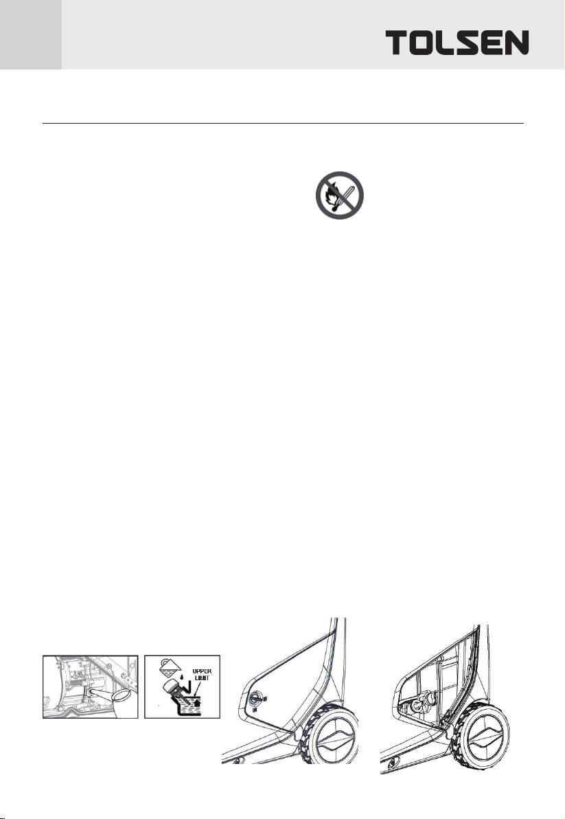
1. Make sure the Engine is stopped and is level.
2. Close vent on Gas Cap.
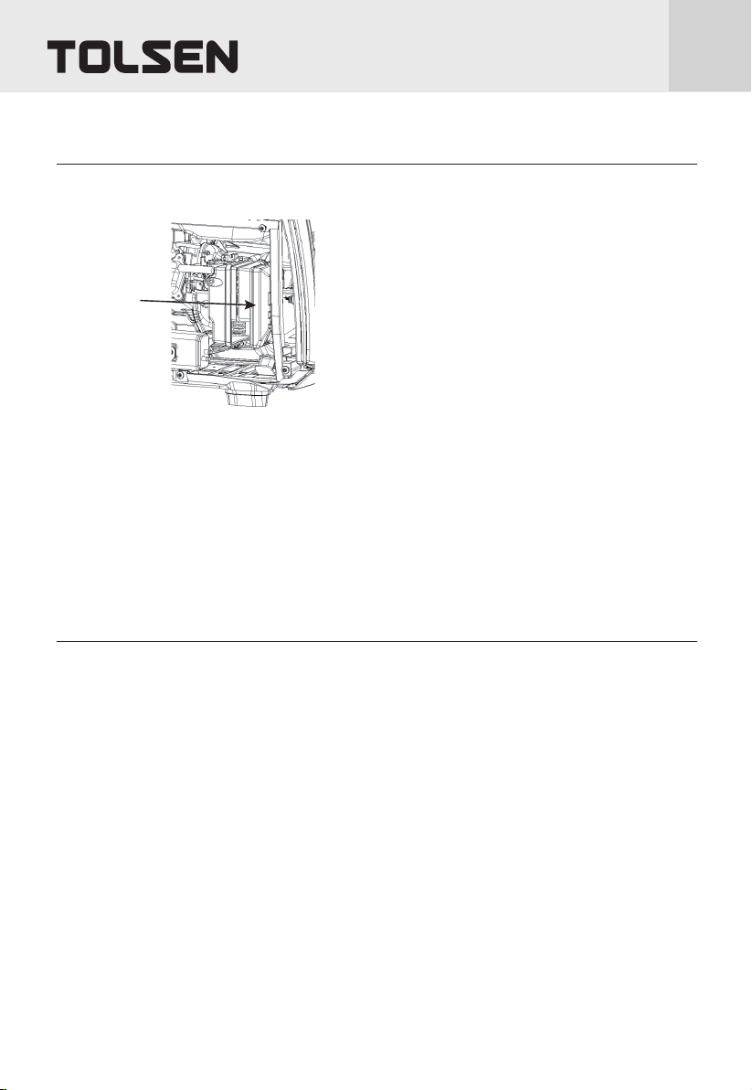
3. On the right side of the Generator, remove the three Screws at the top and remove the Access Panel, as
shown to the right.
4. Clean the top of the Dipstick and the area around it. Remove the Dipstick, turning it counterclockwise.
5. Check the oil level. The oil level should be up to the edge of the hole as shown.
6. As needed, add the appropriate type of oil until the oil level is at the proper level. SAE 10W-30 oil is
recommended for general use.
7. Thread the Dipstick back in clockwise and replace the Access Panel.
NOTICE: Do not run the engine with too little oil. Engine will shut off if engine oil level is too low.
Checking and Filling Engine Oil
WARNING! TO PREVENT SERIOUS INJURY FROM FIRE:
Fill the fuel tank in a well-ventilated area away from ignition sources. If the Engine is hot from use, shut the
Engine off and wait for it to cool before adding fuel. Do not smoke.
1. Clean the Fuel Cap and the area around it.
2. Unscrew and remove the Fuel Cap.
3. Remove the Strainer and remove any dirt and debris. Then replace the Strainer.
NOTE: Do not use gasoline containing more than 10% ethanol (E10). Do not use E85 ethanol.
NOTE: Do not use gasoline that has been stored in a metal fuel container or a dirty fuel container. it can
cause particles to enter the carburetor, affecting Engine performance and/or causing damage.
4. If needed, fill the Fuel Tank to about 1 inch under the fill neck of the Fuel Tank with 87 octane or higher
unleaded gasoline that has been treated with a fuel stabilizer additive. Follow fuel stabilizer
manufacturer’s recommendations for use.
5. Then replace the Fuel Cap.
6. Wipe up any spilled fuel and allow excess to evaporate before starting engine. To prevent FIRE, do not
start the engine while the smell of fuel hangs in the air.
NOTE: Fill Fuel Tank completely before first use. Fuel Tank needs to be completely full to properly prime
Carburetor.
Starting the Engine
Manual Start
OPERATING INSTRUCTIONS 11
Before Starting the Engine
a. inspect the generator and engine.
b. Disconnect all electrical loads from the generator.
c. Fill the engine with the proper amount and type of both stabilizer-treated unleaded gasoline and oil.
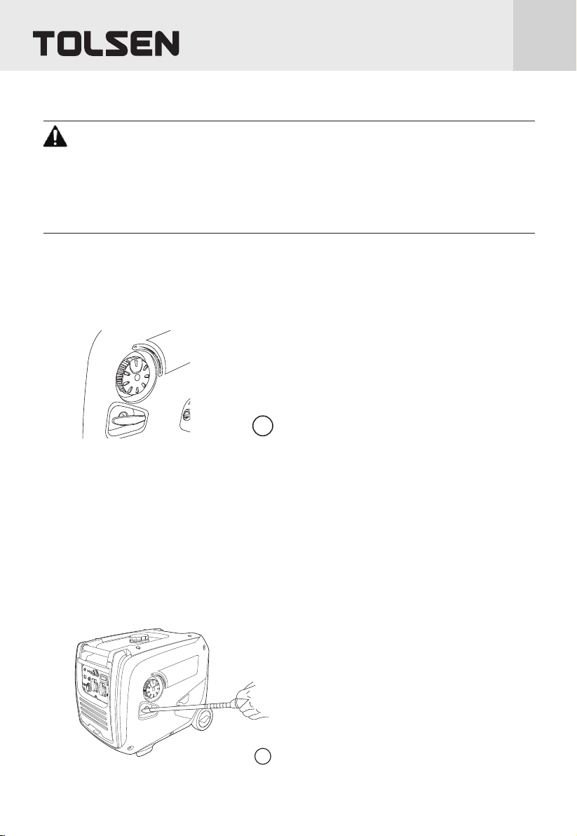
1. Move the Economy (ECO) Switch to the OFF position.
2. Turn the Combination Switch to the CHOKE position.
3. Grip the Starter Handle of the Engine loosely and pull it slowly several times to allow the gasoline to flow
into the Engine’s carburetor. Then pull the Starter Handle gently until resistance is felt. Allow Cable to
retract fully and then pull it quickly. Repeat until the Engine starts. Do not let the Starter Handle snap
back against the housing. Hold it as it recoils so it doesn't hit the housing.
NOTE: If engine does not start, check engine oil level. Engine will not start with low or no engine oil.
NOTE: If warm engine does not start, turn Combination Switch to RUN before trying to start it again.
1/2
3

Nominal 12VDC Output
4. Allow the engine to run for several seconds. Wait for the output light to light up.
5. Then, move the combination switch slowly to its run position.
NOTE: Moving the Combination Switch too fast could stall the Engine.
IMPORTANT: Allow the Engine to run at no load for five minutes with no load aer each start-up so that the
Engine can stabilize.
OPERATING INSTRUCTIONS
12
Break-in period:
a. Breaking-in the Engine will help to ensure proper equipment and Engine operation.
b. The break-in period will last about 30 hours of use. DO NOT exceed 75% of the Generator’s running
wattage during this period.
• Change the engine oil aer this period.
Under normal operating conditions subsequent maintenance follows the schedule explained in the
MAINTENANCE section.
1. Do not use any 230VAC outlet while using the 12VDC outlet.
2. Move the Economy (ECO) Switch to the OFF position.
3. Only use the 12VDC receptacle to charge a 12 volt lead-acid type battery using an appropriate charge
controller. (Battery and controller not included.) The 12VDC output is not regulated.
4. Do not connect any device to the 12VDC terminal that draws more than 8.3 amps.
5. If this 12VDC circuit protection is tripped, reduce the load, and press the Reset Button next to the outlet.
4
5
Move
solwly
Reset
button

Connecting 230VAC Loads to the Generator
OPERATING INSTRUCTIONS 13
Overload Light
NOTE: The OVERLOAD light may turn on for a few seconds as a large device starts up. This is normal for
loads approaching the capacity of this Generator.
1. The total combined load through the outlet on the Generator must not exceed the running power of the unit.
2. If the OVERLOAD light turns on and the Generator stops producing power, it has been overloaded.
3. Disconnect all electrical devices, and compare device requirements to Generator rating. Move anything that may
be limiting Generator ventilation away.
4. Press and hold Overload Reset button above the Dual 120VAC Receptacle until OVERLOAD light turns off.
5. Reconnect devices while being careful to not overload Generator.
Economy (ECO) Switch
1. Turn the Economy Switch ON to limit noise and fuel consumption for lighter generator loads.
2. Turn the Economy Switch OFF to operate engine at full speed:
a. when starting,
b. when a heavy load is applied, or
c. when using the 12VDC output.
Overload
reset button

Stopping the Engine
OPERATING INSTRUCTIONS
14
To stop the Engine in an emergency, turn the Combination Switch off.
Under normal conditions, use the following procedure to shut off the Generator:
1. Turn all electrical load devices off and unplug them from the Generator.
2. Turn the Combination Switch off.
Unplug loads
1
2

Cleaning, Maintenance, and Lubrication Schedule
MAINTENANCE
OPERATING INSTRUCTIONS 15
TO PREVENT SERIOUS INJURY FROM ACCIDENTAL STARTING: Turn the Combination Switch of the
equipment to its “OFF” position, wait for the engine to cool, and disconnect the spark plug cap before
performing any inspection, maintenance, or cleaning procedures. TO PREVENT SERIOUS INJURY
FROM EQUIPMENT FAILURE: Do not use damaged equipment. if abnormal noise, vibration, or excess
smoking occurs, have the problem corrected before further use. Follow all service instructions in this
manual. The engine may fail critically if not serviced properly
Many maintenance procedures, including any not detailed in this manual, will need to be
performed by a qualified technician for safety. if you have any doubts about your ability to safely service
the equipment or engine, have a qualified technician service the equipment instead.
NOTE: This maintenance schedule is intended solely as a general guide. If performance decreases or if
equipment operates unusually, check systems immediately. The maintenance needs of each piece of
equipment will differ depending on factors such as duty cycle, temperature, air quality, fuel quality, and
other factors.
NOTE: The following procedures are in addition to the regular checks and maintenance explained as
part of the regular operation of the engine and equipment.
procedure Before
Each use
Monthly or
every 8 hr. of
use
Every 3
mo. or 50
hr. of use
50 hr. of use
Every 6 mo.
or 100 hr. of
use
yearly or
every 300
hr. of use
Every 2
years
Brush off outside of engine
Check engine oil level
Check air filter
Change engine oil
Clean/replace air cleaner *
Check and clean spark plug
1. Check/adjust idle speed
2. Check/adjus tvalve
clearance
3. Clean fuel tank, strainer and
carburetor
4. Clean carbon build-up from
combustion chamber
** **
Replace fuel line if necessary **
*Service more frequently when used in dusty areas.
**These items should be serviced by a qualified technician.
Checking and Filling Fuel
OPERATING INSTRUCTIONS
16
WARNING! TO PREVENT SERIOUS INJURY FROM FIRE:
Fill the fuel tank in a well-ventilated area away from ignition sources. If the engine is hot from use, shut the
engine
Off and wait for it to cool before adding fuel. Do not smoke.
1. Clean the fuel cap and the area around it.
2. Unscrew and remove the fuel cap.
3. Remove the strainer and remove any dirt and debris. Then replace the strainer.
NOTE: Do not use gasoline containing more than 10% ethanol (E10). Do not use E85 ethanol. Add fuel
stabilizer to the gasoline or the Warranty is VOID.
NOTE: do not use gasoline that has been stored in a metal fuel container or a dirty fuel container. It can cause
Particles to enter the carburetor, affecting engine performance and/or causing damage.
4. If needed, fill the fuel tank to about 1 inch under the fill neck of the fuel tank with 87 octane or higher
unleaded gasoline that has been treated with a fuel stabilizer additive. Follow fuel stabilizer
manufacturer’s recommendations for use.
5. Then replace the fuel cap.
6. Wipe up any spilled fuel and allow excess to evaporate before starting engine. To prevent fire, do not start
the engine while the smell of fuel hangs in the air.
Engine Oil Change
CAUTION: oil is very hot during operation and can cause burns. Wait for engine to cool before changing oil.
1. Make sure the engine is stopped and is level.
2. Close vent on gas cap.
3. Remove the access panel on the right side of the generator.
4. Clean the top of the oil fill plug and the area around it. Remove the oil fill plug, turning it counterclockwise.
5. Place the generator on stands with the oil fill centered over an oil drain pan. Tilt the generator over the oil
drain pan and wait for oil to drain completely. Recycle used oil.
6. Set the generator back down on a level surface. Add the appropriate type of oil until the oil level is at the
proper level. Sae 10w-30 oil is recommended for general use.
7. Check the oil level. The oil level should be up to the edge of the hole as shown.
8. Thread the oil fill plug back in clockwise and replace the access panel.
OPERATING INSTRUCTIONS 17
AIR Filter Element Maintenance
Spark plug Maintenance
1. Remove the Access Panel on the right side of the Generator.
2. Remove the Air Filter Cover and the air filter elements and check for dirt. Clean as described below.
3. Cleaning:
• For “paper” filter elements: To prevent injury from dust and debris, wear ANSI-approved safety goggles,
NIOSH-approved dust mask/respirator, and heavy-duty work gloves. In a well-ventilated area away from
bystanders, use pressurized air to blow dust out of the air filter.
• For foam filter elements: Wash the element in warm water and mild detergent several times. Rinse. Squeeze
out excess water and allow it to dry completely. Soak the filter in lightweight oil briefly, then squeeze out
the excess oil.
4. Install the cleaned filter.
5. Secure the Air Filter Cover and replace the Access Panel before use.
Air filter cover
1. Remove Access Panel from right side of Generator.
2. Disconnect spark plug cap from end of plug. Clean out debris from around spark plug.
3. Inspect the spark plug: If the electrode is oily, clean it using a clean, dry rag. If the electrode has deposits on it,
polish it using emery paper. If the white insulator is cracked or chipped, the spark plug needs to be replaced.
Using an incorrect spark plug may damage the engine.
4. When installing a new spark plug, adjust the plug’s gap to the specification on the Specifications chart. Do not
pry against the electrode, the spark plug can be damaged.
5. Apply anti-sieze material to Spark Plug threads. Install the new spark plug or the cleaned spark plug into the
engine.
• Gasket-style: Finger-tighten until the gasket contacts the cylinder head, then tighten about 1/2-2/3 turn more.
• non-gasket-style: Finger-tighten until the plug contacts the cylinder head, then tighten about 1/16 turn more.
NOTICE: Tighten the spark plug properly. if loose, the spark plug will cause the engine to overheat. IF
overtightened, the threads in the engine block will be damaged.
6. Apply dielectric spark plug boot protector (not included) to the end of the spark plug and reattach the cap
securely.
7. Replace Spark Plug Access Cover and Access Panel.

TROUBLESHOOTING
problem possible Causes probable Solutions
Engine misfires 1. Spark plug cap loose.
2. Incorrect spark plug gap or
damaged spark plug.
3. Defective spark plug cap.
5. Incorrect compression.
1. Check cap and wire connections.
2. Re-gap or replace spark plug.
3. Replace spark plug cap.
4. Use only fresh 87+ octane stabilizer-treated unleaded
gasoline. Do not use gasoline with more than 10%
ethanol (E15, E20, E85, etc.).
5. Diagnose and repair compression. (Use Engine will not
start: COM PRESSION RELATED section.)
Engine stops suddenly
1. Fuel tank empty or full of impure or
low quality gasoline.
2. Low oil shutdown.
3. Defective fuel tank cap creating
vacuum, preventing proper fuel flow.
4. Faulty magneto.
5. Disconnected or improperly
connected spark plug cap.
1. Fill fuel tank with fresh 87+ octane stabilizer-treated
unleaded gasoline. Do not use gasoline with more than
10% ethanol (E15, E20, E85, etc.).
2. Fill engine oil to proper level. Check engine oil before
EVERY use.
3. Test/replace fuel tank cap.
4. Have qualified technician service magneto.
5. Secure spark plug cap.
Engine stops when under
heavy load
1. Dirty air filter
2. Engine running cold.
1. Clean element.
Engine knocks
1. Old or low quality gasoline.
2. Engine overloaded.
3. Incorrect spark timing, deposit
buildup, worn engine, or other
mechanical problems.
1. Fill fuel tank with fresh 87+ octane stabilizer-treated
unleaded gasoline. Do not use gasoline with more than
10% ethanol (E15, E20, E85, etc.).
2. Do not exceed equipment’s load rating.
3. Have qualified technician diagnose and service engine.
Engine backfires
1. Impure or low quality gasoline.
2. Engine too cold.
3. Intake valve stuck or overheated
engine.
4. Incorrect timing.
1. Fill fuel tank with fresh 87+ octane stabilizer-treated
unleaded gasoline. Do not use gasoline with more than
10% ethanol (E15, E20, E85, etc.).
2. Use cold weather fuel and oil additives to prevent
backfiring.
3. Have qualified technician diagnose and service engine.
4. Check engine timing.
Attached device doesn’t
have power
1. Device not plugged in properly.
2. Circuit Breaker tripped.
1. Turn off and unplug the device, then plug it back in
again and turn on.
2. Turn off and unplug device, reset Circuit Breaker, plug
in device and turn on.
Attached device begins to
operate abnormally
1. Problem with device.
2. Rated load capacity exceeded.
1. Immediately unplug device. Have device repaired by a
qualified technician, or replace device.
2. Lower the number of items plugged into the generator
to stay within the rated capacity, or use a more powerful
generator.
3. Product needs service.
4. Old or low quality gasoline.
TROUBLESHOOTING
18
ASSEMBLY DIAGRAM & PARTS LIST
ASSEMBLY DIAGRAM & PARTS LIST 19
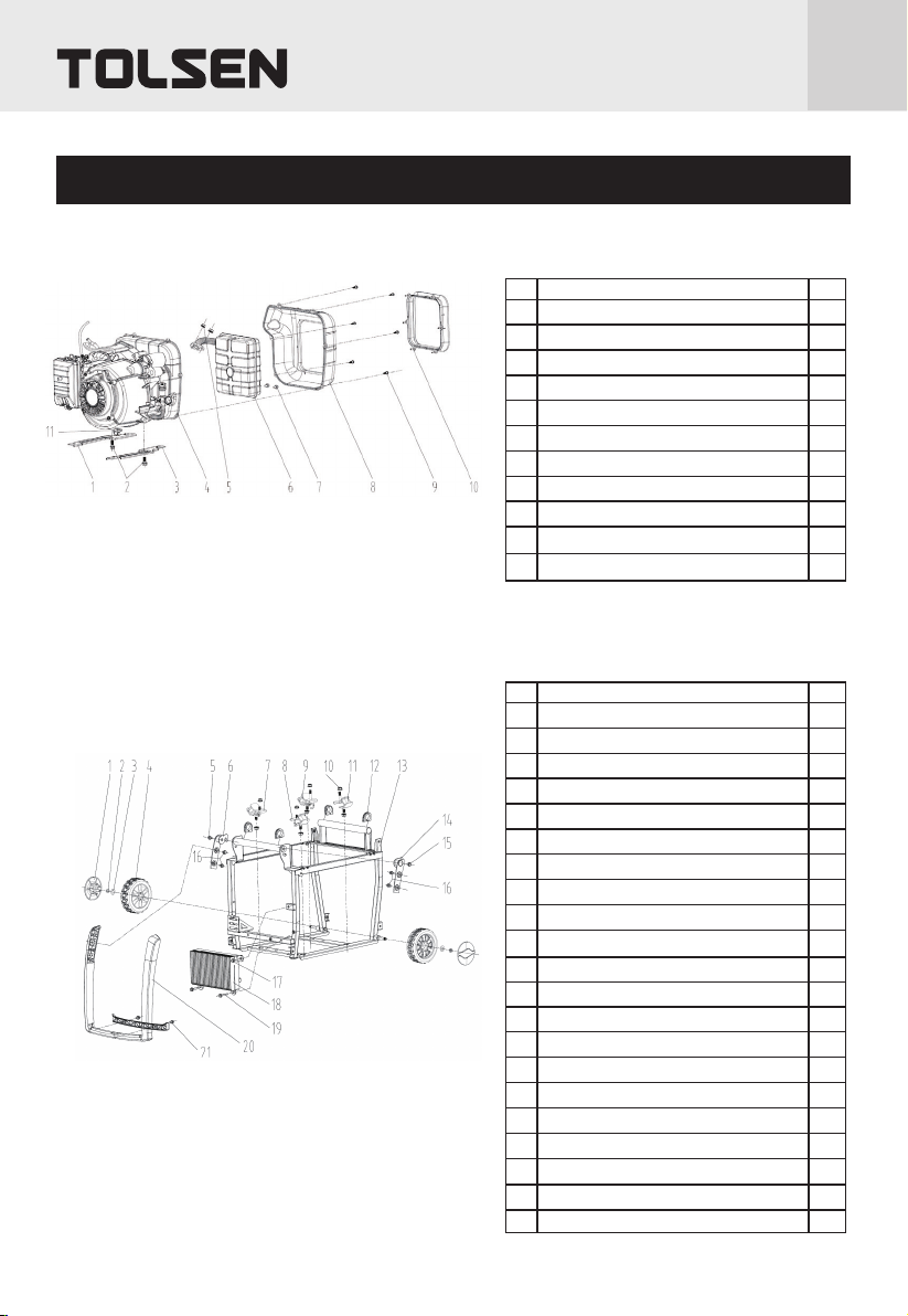
A-ENGINE
NO. Description Qty
1
2
3
4
5
6
7
8
9
10
11
Fixing holder,Engine
Hexagonal flange bolt
Fixing holder,Engine
Engine assy.
Hexagonal nut
Muffler assy.
Hexagonal flange bolt
Muffler tail cover
Cross recessed pan head self threading screw
Air guide sleeve,Muffler
Baffle
1
2
1
1
2
1
2
1
6
1
1
B1-FRAME ASSY
NO. Description Qty
1
2
3
4
5
6
7
8
9
10
11
12
13
14
15
16
17
18
19
20
21
Ornament shell
Steel Hexagonal lock nut
Gasket-grade C
Wheel assy.
Hexagonalal step bolt
Handle hose connecter
Le shock pad assy.
Right shock pad assy.
Le shock pad assy.
Hexagonal flange nut
Right shock pad assy.
Ornament rubber sleeve
Frame assy.
Handle hose connecter
Hexagonal step bolt
Hexagonal flange bolt
Hexagonal flange bolt
Inverter assy.
Hexagonal flange bolt
Handle pipe assy.
Ornament shell
2
2
2
2
1
1
1
1
1
4
1
1
1
1
2
2
1
1
2
1
1

C-OIL TANK ASSY
NO. Description Qty
1
2
3
4
5
6
7
8
9
10
Oil cap assy.
Oil filter assy.
Oil tank assy.
Hexagonal flange bolt
Gasket,Oil tank
Bushing
Shock rubber pad,Oil tank
Clamp
Oil pipe
Oil leveler assy.
1
1
1
4
4
4
4
1
1
1
B2-FRAME ASSY
NO. Description Qty
1
2
3
4
5
6
7
Nut
Square nut
Baseplate assy.
Ornament shell
Shock seat assy.,Frame
Hexagonal flange bolt
Hexagonal flange nut
4
2
1
1
2
2
4
20 ASSEMBLY DIAGRAM & PARTS LIST
Table of contents
Other TOLSEN TOOLS Portable Generator manuals


