TomTec 400 User manual

1
Table of Contents
Preface………………………………………………………………………... 2
CHAPTER 1.......................................................................................... 3
Introduction………………………………………………………………….. 4
QUADRA TOWER Specifications………………………………………….
5
Warnings, Cautions, Notes and Symbols…………………………………... 6
Requirements………………………………………………………………... 7
Installation…………………………………………………………………… 8
CHAPTER 2…………………………………………………………. 8
Getting Started……………………………………………………….……… 9
Program Mode……………………………………………………................. 10
Parameter Values………………………………………….………………… 11
Manual Mode………………………………………………………………... 12
CHAPTER 3.......................................................................................... 14
Quadra Tower Operations………………………………………………….. 15
Advanced Program Features……………………………………………….. 16
Diagnostics…………………………………………………………………… 20
Aspirate and Dispense Logic………………………………………………... 23
Accuracy and Precision……………………………………………………... 23
QUADRA TOWER Sample Programs…………………………………….. 24
CHAPTER 4.......................................................................................... 26
Fuse Replacement............................................................................................ 27
TOMTEC’s Warranty Policy………………………………………………. 29
TOMTEC’s Return Policy………………………………………………….. 29
Quality Control Testing…………………………………………………….. 30
Certificate of Decontamination……………………………………………... 35
Contacting TOMTEC, Inc.…………………………………………………. 36

2
Preface
The Employees of TOMTEC wish to thank you for purchasing our QUADRA
TOWER.
This manual provides general information, installation instructions and operation
for the QUADRA TOWER.
Every effort has been made to avoid errors in text and diagrams; however,
TOMTEC, Inc. assumes no responsibility for any errors, which may appear in
this publication.
It is the policy of Tomtec, Inc. to improve products as new techniques and
components become available. Tomtec, Inc. therefore reserves the right to change
specifications at any time.
We would appreciate any comments on this publication.
TOMTEC, Inc.
1000 Sherman Avenue, Hamden, CT 06514 USA
Phone: (203) 281-6790 Fax: (203) 248-5724

3
CHAPTER
1
General Information
This chapter give background information on
the QUADRA TOWER
Section Includes:
•Introduction
•Specifications
•Accessories
•Standard Warnings, Cautions, Notes
and Symbols used in this Operators
Manual

4
Introduction
Congratulations on the purchase of your QUADRA TOWER
The pipettor instrument is designed to be operated either manually from the front
operator’s panel or through user defined programs.
The overall dimensions of this instrument and the built in flexibility offer a
comprehensive pipetting unit in a very small footprint.
Up to forty Programs can be created and saved within the unit.
CAUTION:
IF THE INSTRUMENT IS USED IN A MANNER
NOT SPECIFIED BY THE TOMTEC
INC., THE PROTECTION BY THE INSTRUMENT
MAY BE IMPAIRED.
NOTE: The Model 400 QUADRA TOWER™ is designated for use with various
liquids and aqueous solutions with a pH near neutral. As the pH of the solution
moves away from neutral, various parts may be affected, depending o the length of
time they are in contact. The user has full responsibility for the selection of
compatible liquids, and for thoroughly rinsing the system after each use.
Damage resulting from improper use of liquids may void the warranty.

5
Specifications
QUADRA TOWER
Environmental Specifications
Operating
environment
INDOOR USE ONLY
•Temperature: 5 °C to 40 °C (41 °F to 104 °F)
•Humidity: 20%–90% (no condensation)
Storage
environment
•Temperature: 0 °C to 60 °C (32 °F to 140 °F)
•Humidity: 5%–90% (no condensation)
Physical Specifications
Dimensions
•Width: 11.75 in. (298.54mm)
•Depth: 14.00 in. (546.10mm)
•Height: 24.50 in. (622.30mm)
Weight
•85.0 lbs (38.55 kg)
Electrical Specifications
Power
requirements
•100 – 120VAC, 50/60 Hz @ 2.0 Amp
or
•230 – 240VAC, 50/60 Hz @ 1.0 Amp
Pneumatic Specifications
Compressed air
requirements
•Internal Compressor supplies required air
(20 – 35 PSI if external supply is used)
6
Warnings, Cautions, Notes & Symbols
Throughout this manual, there may be blocks of text printed in bold type within
boxes or italic type. These blocks are warnings, cautions, and notes, and they are
used as follows:
Note: A NOTE indicates important information that helps you make
better use of the QUADRA TOWER.
Throughout this manual, there may be symbols within triangles, and they are used
as follows:
WARNING:
A WARNING indicates the potential for bodily harm
and tells how to avoid the problem.
CAUTION:
A CAUTION indicates either potential damage to
hardware or loss of data and tells how to avoid the
problem.
The lighting flash with arrowhead symbol, within an equilateral
triangle, is intended to alert the user to the presence of non-
insulated “dangerous voltage” within the product’s enclosure
that may be of sufficient magnitude to constitute the risk of
electric shock.
The exclamation point within an equilateral triangle is
intended to alert the user to the presence of important
operating and maintenance instructions within the literature.

7
REQUIREMENTS
To install the Model 400 Series QUADRA TOWER check that the following
services are available:
Power source: 100 – 125VAC or 220 – 240VAC, 50/60Hz depending on model.
Optional: Compressed air source 35 – 125 PSI unregulated.
The following items supplied with the QUADRA TOWER is required for the
installation:
Line Cord - Catalog Number 827-001-03 for Domestic and Japan, Catalog
Number 827-210-25 for Europe or Catalog Number 827-001-03 for the United
Kingdom.
AIR PRESSURE CONNECTION
TOMTEC Inc. has incorporated a compressor for the QUADRA TOWER.
However, laboratory air may be used with the external air supply kit (CAT. # 430-
10) instead of the on board compressor.
INSTALLATION
•Connect the correct Line Cord to the power module located on the right side of
the QUADRA TOWER.
•Connect the plug to the correct AC power supply.
WARNING:
TO HELP PREVENT ELECTRICAL SHOCK,
PLUG THE QUADRA TOWER INTO A
PROPERLY GROUNDED POWER SOURCE.
THE CABLE SUPPLIED WITH DOMESTIC
UNITS IS EQUIPPED WITH A THREE
PRONGED PLUG TO ENSURE PROPER
GROUNDING. DO NOT USE AN ADAPTER
PLUG OR REMOVE THE GROUNDING PLUG
FROM THE CABLE; USE A THREE-WIRE
CABLE WITH PROPERLY GROUNDED PLUGS.

8
CHAPTER
2
Installation
This chapter tells you how to connect and
operate the QUADRA TOWER
Section Includes:
•Getting Started
•Program Mode
•Manual Mode

9
Getting Started
QUADRA TOWER
Operator’s Panel
Prior to any operations the QUADRA TOWER must be initialized. This simple
procedure allows the system to run a ‘self-check’ sequence, and then enter the
“Standby mode”. The Procedure is as follows:
•Press the <Run> button.
Once this has been accomplished the QUADRA TOWER can now run a program
from its memory, or be put into the “Manual Mode” to create a user program.
Loading & Shucking Tips:
Now that the unit has been initialized the tips can be loaded.
To Load:

10
To load tips onto the pipettor
head, the Tip Jig (filled with the
appropriate tips) must be placed
level into the wash station as
shown to the left. Pressing <Load
Tips> activates the sequence.
Remove the Tip Jig.
To Shuck:
Simply reverse the procedure
above. Place the Tip Jig back into
the wash station, again making
sure it is well seated in place.
Press <Shuck Tips> to activate
the function. Now you can
remove the Tip Jig, filled with the
tips, to whatever your purpose
may be.
Running a Program
In the interest of a ‘quick start’, the operator can run a stored program by using the
following procedure:
•From the QUADRA TOWER banner message, press <SELECT> to select
“Programs XX” (01 thru 40). Use the Program <up/down> arrows to search
for the desired program number.
SELECT UP / DOWN RUN
Selects 1 of 40
programs
Selects Program
number
Executes
selected program
•Press <RUN> to execute the program.
•You can press <Stop> to pause the program operation at any time.
•Press the <Run> key at anytime to resume or <Stop> again to abort.
Program Mode – Operation
Both units have 40 user configurable programs numbered 01 – 40 that are accessed
through the Front Panel in the SETUP mode. Each program consists of four cycles.
Each cycle contains several functions and parameters which are listed below in
table form. During each step in each cycle, the cycle number (1-4) appears as the
first number on the screen. Please note that the front panel programming is
mirrored in the QUADRA TOWER Program Editor program for your Windows™
based computer. Some users may find that programming in the QUADRA
TOWER Program Editor, then downloading this information to the QUADRA
TOWER may be more efficient than programming directly on the unit.
To create a new program, or edit an existing program, use the following procedure:

11
•Turn on the QUADRA TOWER.
•From the QUADRA TOWER banner message, press <SETUP> to select
“Programs XX” (01 thru 40).
NOTE: Use the Scroll <up/down> arrows to search for the desired
program number. Use the Cursor <right> arrow to search for the
desired program parameter.
SETUP SCROLL UP /
DOWN
CURSOR
RIGHT
Selects
Programs
Selects Program
number
(01 – 40)
Selects
Program
parameter
Parameter Value
Tray Station
1 to 5 – 1 to 4 are the sliding trays and station 5 is the wash bath.
NOTE: use the tip load jig on top of the wash reservoir to load and
unload tips
Tip Height #1 Pressing “Run” will cause the pipettor head assembly to come to a
preset height for the selected station. This preset height is
approximately 1/16 inch (1.5mm) from the bottom of the plate or
reservoir on the selected station. The operator may accept this height
or scroll up or down to the desired height for the application.
As, Ds, aG
V#1:
Aspirate liquid (As), Dispense liquid with touch off (Ds) or Agar –
dispense without touch off (aG). Volume set for this parameter using
the <up/down> scroll buttons from 0 to 450ul. If volume is set to 0,
then the following two parameters do not appear.
#1: A, D or G - The As, Ds or aG functions can be set.
S: Pipetting Speed. Values are 1-4. TOMTEC recommends 3 for most
applications. Viscous fluids may require a slower speed.
Mx Cyc: Mix cycles (0 to 99) using <up/down> value buttons
Vo: Volume for mix cycle (0 to 450ul) using <up/down> scroll buttons.
If volume is set to 0, then the following four parameters do not
appear.
Mx Asp Ht: Mix Aspirate Height. Values are 0 to 8630.
S: Pipetting speed. Values are 1-4.
Mx Disp Ht: Mix Dispense Height. Values are 0-8630.
S: Pipetting speed. Values are 1-4.

12
Tip Height #2 Tip height is set to go to a preset height for the plate or reservoir.
During each program cycle, only 1 tray can be selected. The user
may then use the <down> scroll or value buttons to fine tune the tip
movement into the tray.
As, Ds, aG
V#2:
Aspirate liquid (As), Dispense liquid with touch off (Ds) or Agar –
dispense without touch off (aG). Volume set for this parameter using
the <up/down> scroll buttons from 0 to 450ul. If volume is set to 0,
then the following two parameters do not appear.
#2: A, D or G - The As, Ds or aG functions can be set.
S: Pipetting Speed. Values are 1-4. Tomtec recommends 3 for most
applications. Viscous fluids may require a slower speed.
W, M, S: Wash Tips (W) pause minutes (M), or pause seconds (S) using the
<up/down> value buttons.
n: Dependent on W, M or S, the program will wash the tips for n cycles
or pause the program for n minutes or n seconds using the
<up/down> scroll buttons from 0 to 99.
Tips E,K,L,S:
Empty (E) is used to dispense any residual and resets the pipetting
volume to 0ul in the head. Skip (K) is used to continue to next cycle
in program. Load (L) is used to load tips from the tip jig. Shuck (S)
is used to “Shuck” or unload tips into the tip jig.
L, N, P, Q, R: Loop with pause (L) is used to loop cycle. Loop with NO pause (N)
is used to loop cycle. Pause (P) will hold the cycle until user
intervenes. Quit (Q) quits the program at this cycle. Continue or
GOTO (R) continues the program or calls for another program that is
defined in the next parameter.
n: Value for L, N, P, Q or R. Value depends upon previous parameter.
This is the end of the first cycle. Each program contains up to four cycles.
Furthermore, in order to expand the programming capabilities, one program can
call (GOTO) another program.
Both units save each step of the program once the user exits by pressing the STOP
button. There is no need to specify a SAVE command. The unit saves programs
automatically upon exiting the program setup mode.
Manual Mode -Operation
Manual operations on the Quadra Tower are performed using the Manual Mode
Buttons and Tray Buttons. The user may start by:
1. Adding reagent reservoirs or plates as the user finds necessary on the trays.
2. Loading tips onto the pipettor head.
3. Selecting the Aspirate Button without selecting a tray button. This method will
allow the user to pipette and air gap before aspirating liquid samples.
4. Select a tray button then select Aspirate button. This method will allow the user
to pipette directly out of the tray without an air gap.
ASPIRATE:

13
Air gap? <nnn> - Allows user to define air gap µl (0-450ul)
Vol? <nnn> - Volume to Aspirate
AsHt: <nnnn> - A default height is preset. This height is approximately
1/16 inch (1.5mm) from the bottom of the plate or reservoir on that station.
The operator may scroll up or down from this height to the desired height.
This aspirate button with no selected trays will allow the user to define in micro
liter volume, the air gap before pipetting a liquid. Furthermore, with a tray pre-
selected, this function will aspirate a volume (up to 450µl) at a user defined height.
DISPENSE:
Vol? <nnn> - Volume to Dispense
DsHt: <nnnn> - A default height is preset. This height is approximately
3/16 inch (5mm) from the bottom of the plate or reservoir on this station. It
is 1/8 inch (3.5mm) higher than the default aspirate height described above.
The operator may scroll up or down from this height to the desired height.
Once liquid or air has been aspirated, the user may then dispense this sample into a
selected tray, or without selecting trays 1-4 then the pipetting head will dispense
the sample into the wash reservoir. The dispense height is user defined.
LOAD TIPS:
The user must place tip load jig on top of wash reservoir. Furthermore, make sure
that no tips are already on the pipettor head.
SHUCK TIPS:
The user must place tip load jig on top of wash reservoir. The tip load jig must
also be empty before shucking tips off of the pipettor head.
WASH TIPS:
Vol? <nnn> - Volume to wash tips
DsHt: <nnnn> - Dispense height of pipettor head – Aspirate height is
predetermined in the settings
The user must make sure that the tip load jig is removed. The wash tips function
performs a tip wash in the wash reservoir. The aspirate height is user defined.
Function Buttons
<F1> - Upload or Download programs to Quadra Tower Program Editor.
QUADRA TOWER must be connected to a Windows™ based computer via serial
connection. Use <up/down> scroll or value buttons to change parameter.
<F2> - Diagnostic parameters. Tomtec Service uses this tool.
<F2><F2> - Alignment Wizard. The alignment wizard is selected by pressing the
F2 button twice. To use, the operator should place a standard SBS 96 well
microplate on each of tray station 1,2,3, and 4. Pressing <Run> will cause the
pipettor head to move to a height just above the wells. The nest, holding the
microplate, may be aligned to the tips by loosening the four screws securing the
nest. After alignment the screws are retightened.
<SETUP><SETUP> - Global Parameters

14
CHAPTER
3
Technical Data &
Trouble Shooting
This chapter covers a deeper understanding of
QUADRA TOWER usage along with
troubleshooting.
Section Includes:
•QUADRA TOWER operations
•Advanced Program Features
•Diagnostic Display
•Aspirate and Dispense Logic
•Accuracy & Precision
•QUADRA TOWER Sample
Programs
15
QUADRA TOWER OPERATIONS
The QUADRA TOWER is designed for use by a variety of individuals with
various pipetting skills and requirements. For those who have simple aspirate and
dispense tasks, they may not want to set up automated programs. The TOWER has
manual pushbuttons to facilitate this simple type of operation, select the volume,
set the tip height and execute the function.
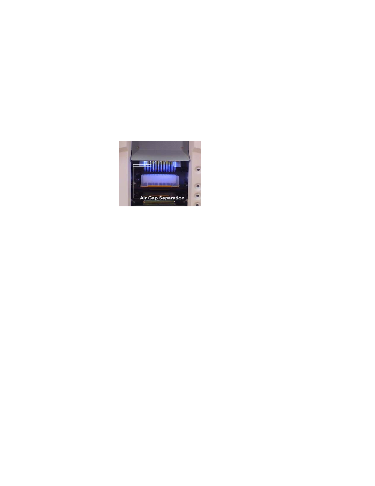
The QUADRA TOWER will accommodate pipeline pipetting. This is aspirating
several aliquots into the tips and separating each with an air gap. The higher
volume buffer or diluents should be aspirated first. The compound, or specific test
reagent, which is normally a smaller volume, should be aspirated last. On the final
dispense, the larger volume buffer is used to wash out the smaller volume reagent.
This will improve your pipetting precision.
When using pipeline pipetting
with separation air gaps, it is
recommended that the first
dispense be made near the top of
the well. This will prevent the air
gaps from creating air bubbles in
the bottom of the well. Air
bubbles can affect the readout on
some applications.
Normally, the dispense function is followed by a mix function using titration. The
QUADRA TOWER program allows setting the number of mix cycles, the volume
to be mixed, the aspirate height, and the dispense height. The number of mix
cycles is dependant on the application. Three is a reasonable number but more
may be beneficial. The aspirate height should be set near the bottom of the well.
The dispense height should be set near the top. This turns the liquid over on each
cycle. The volume should be set for approximately 70% of the liquid volume in
the well.
Again, this facilitates turning the liquid over rather than moving it up and down
within the tip. If the liquid is low in viscosity, i.e., mainly aqueous, you may use
mix speed 3 or 4. However, if the liquid has noticeable viscosity, then mix speed 1
or 2 is desired. If the mix speed is too fast, the liquid will not flow up into the tip
at the same rate the piston moves. That condition is not conducive to good mixing.
Adding Cycles
The programming of the QUADRA TOWER is set up using 4 cycles per program.
Four cycles are not sufficient for many programs. Thus, after 4 cycles in one
program, you may automatically call 4 more cycles in another program. The only
limit is that the memory of the QUADRA TOWER will only accommodate a total

16
of 40 programs of 4 cycles each. As stated above, additional programs may be
stored on a computer and downloaded to the QUADRA TOWER.
The cycles are structured to facilitate programming. The first four steps select a tip
height, a volume, an aspirate or dispense function. This is followed by the
availability of a mix function asking cycles and volumes. If either mix cycles or
volume is set to zero, the mix function is skipped. If a number of cycles is set,
along with a volume, then an aspirate and dispense height are added. This is
followed with another height – aspirate - dispense set of functions.
Having two aspirate/dispense functions in a cycle facilitates aspirating an air gap
then a reagent. This also accommodates the dispense function, followed by a mix
sequence, followed by the dispensing of the blow out air gap.
Following these functions, comes the parameter for the tips. The tips may be
‘Shucked’ (S), ‘Loaded’ (L), or ‘Emptied’ (E). If (S) or (L) is selected, the
program automatically pauses with the pipettor head at the top or home position.
This allows the operator to place the tip jig on top of the wash station. The
operator then must push run to continue the program. If ‘Empty’ (E) is selected,
the pistons will move to their home or empty position. If liquid is in the tips, it will
be dispensed at the present location.
The final parameter is the ‘Loop’ function (L). This causes the cycle that has just
been finished to repeat. A timed delay can be created by selecting ‘Minutes’ (M)
or ‘Seconds’ (S). The other parameter is ‘Pause’ (P) or ‘Run’ (R). A pause stops
the program until the operator presses the run button to commence action. ‘Run’
(R) allows the program to go to the next cycle. The last parameter is the
continuation. If (L) is set, this number determines how many loops are made. If
this is the 4th cycle ending this program, the continuation parameter calls the next
program for an additional 4 cycles.
Advanced Program Features
The desire of a low cost instrument design creates compromise in the operators
interface. Various programming conveniences are provided by creative
multifunctional use of the available push buttons. These special features are
described as follows:
Setting default program heights:
The height of the tips is controlled by a stepper motor drive moving the head
assembly between pipetting stations. The display shows the number of steps the
head is moving from its home or up position. Each step equates to .001 inch of
vertical travel, i.e., 62 steps equals 1/16 inches, 125 steps equals 1/8 inches, 39
steps equal one millimeter.
To facilitate setting heights for each of the stations, the program uses preset
default values. The actual value required, may then be scrolled up or down from
this value. When in the program mode, selecting a tray and pressing run will cause
that tray to extend. (Pressing F2 will cause the tray to withdraw.) The head will
come to the safe height for that tray. The safe height is set in software it brings the
head assembly to a safe height to a selected station. The safe height provides
sufficient room to change the plate or reservoir as necessary.
Pressing F2 and holding it momentarily, will access the tray safe heights. They are
initially preset by TOMTEC to clear a conventional micro plate on station 3 and 4.
The safe height on station 1 and 2 is set to clear a reservoir. These may be changed
to suit operator preference.
The next height selection in the program is for the volume functions. The default
value is preset by TOMTEC to be near the bottom of a conventional micro plate.

17
This is chosen to be approximate, to minimize scrolling to the desired actual value.
You may scroll the value up or down to the required setting for your application.
Pressing “Run” will move the head assembly to this value. Pressing F2 will bring
it up. If set too low, the stage safety error will appear.
Correcting errors during a run:
Errors of various types may occur while running a cycle. The QUADRA TOWER
programming provides several ways of correcting the error to save the work in
progress. During a program, if the error message occurs, the following corrective
action may be taken.
If an error does occur, the program pauses where it is. Pressing the left cursor key
will show the error message on the display. During the error condition, the
operator has access to the manual push buttons to operate the system manually to
make the required correction. Pressing the program upper scroll button will cause
the head to go up to its home or clear position. The tray buttons provide access to
the plates. The manual aspirate and dispense functions are accessible.
After taking the necessary corrective action, the operator has the choice to return
to the program. If corrective action has failed, pressing the yellow F2 button will
tell the program to “retry” that failed function and proceed to the next. Pressing the
green “run” button, will tell the program to “skip” the function and then proceed.
Pressing the red “stop” button will “abort” the running program.
Some of the pushbuttons have multiple functions. Some are accessed with multiple
pushes. Others are activated at a specific point in the program. They are defined as
follows:
NORMAL OPERATION AS DEFINED BY THE
PUSH BUTTON MARKING
Program Scroll Up: Moves the program access number.
Program Scroll Down: Moves the program access down.
Program Select: Selects the program to be run.
Program Set Up: Selects programming mode of operation.
Parameter Cursor Right: Advances parameter steps.
Parameter Cursor Left: Reverses parameter direction.
Parameter Value Upper: Increase parameter value.
Parameter Value Lower: Decrease parameter value.
Following are the additional functions these
buttons provide:
Setup: Pressing this button twice enters the instrument parameter
mode. This controls the various mechanical operations of the
instrument. “R” stands for the ramp setting for the specific
stepper motor. “S” stands for the stepper motor speed. We
suggest using the factory settings, unless otherwise
necessary.
Carriage: Sets the values for moving the head assembly up and
Down.
Tip Loading:
Sets head motor speed for tip loading.
Tip Shuck:
Sets head motor for this function.

18
Aspirate:
Sets ramp speed for an aspirate function.
Dispense:
Sets ramp speed for a dispense function.
Tip Wash:
Sets piston speed for a wash cycle.
Tip Load
Height:
This sets the height the head assembly comes to, to load tips.
From this setting, the head assembly automatically goes down
500 steps to load the tips.
The software looks for activation of the tip load switch, indicating the tips have
been properly loaded. If the tip load switch is not activated after the first 500 step
increments, the software steps down another 500 step increments looking for the
tip load switch activation. If it occurs again, the procedure is applied a third time.
After the third try, if the tip load switch is not activated, a tip load error occurs.
Please note that the software issues the step command. The stepper motor will
follow the step count within its torque capability. If the opposing force exceeds
the stepper motor torque, the stepper motor simply stalls. After the three
successive attempts, the error message is called for operation correction.
NOTE: the stage safety is bypassed when loading tips.
Tip Shuck
Height:
This is the height the head assembly comes to for shucking
tips.
Pump Shuck
Steps:
This is the number of steps that moves the tip shuck plate to
clear the tip “O” rings to shuck the tips.
µL Liter Factor:
This sets the number of steps per microliter. This is a
calibration factor. See the discussion on accuracy and
precision.
Backlash Factor:
This is the number of steps that the software adds to the
initial movement of the pistons on an aspirate or dispenses
function. It is added any time the pistons make a change in
direction. It is used to improve accuracy at small volumes.
See discussion on accuracy and precision.
Z Offset:
This factor is used to compensate for the mechanical,
dimensional variations between instruments. The Z factor is
used to align the software dimensions to the machine
dimensions. It is a global factor affecting the base line for all
dimensions. It is used to align the head dimensions to the
software values if the head assembly is changed.
After installing and aligning the head assembly, a set of tips are loaded. Place a
piece of paper (20 pound offset is typical), on the metal nest plate of station #1.
From the “Z” offset banner press “run”. The head will move down to its calibrated
height. If the tips are not touching the paper, increase the Z factor setting in the
positive direction (program scroll buttons). If the paper is pinned, decrease the “Z”
factor setting. Use the parameter value button to change from (+) to (-). Set the
“Z” factor so you may just slip the paper out from between the tips and the top of
the nest. Pressing stop will enter this value into the program.

19
Tip Load Light
Switch:
“Yes” or “No”
If “No” is selected, then the setting of the tip load switch is ignored. This should
only be done in an emergency until the tip pin switch can be properly set.
Otherwise, there is no checking function that the tips were properly seated and
sealed.
Manual
Aspirate/Dispense
Speed:
This sets the speed for the manual button functions.
Manual Wash Cycles:
Sets the number of aspirate/dispense cycles used for
the manual wash button selection.
Manual Wash
Aspirate Height:
Sets the aspirate height for the manual wash function.
Yellow F2 Button
This button has several functions depending on the mode of the
current operation.
During a Running
Program:
If an error occurs, to pause the program,
the F2 button signals a “retry” after the
error condition has been remedied.
During the Creation of a
Program:
Pressing F2 will cause the head assembly
to go up to its home position.
When the TOWER is at
“rest” or “standby”:
The first push of F2 brings up a display of
the various light switches in the instrument.
These light switches are used as limit
switches to detect the completion of a
motion. A (1) indicates the light switch is
not blocked. A (O) indicates it is blocked.
The light switch diagnostic display is on
the following pages.
Table of contents
Popular Industrial Equipment manuals by other brands

SPX
SPX Power Team HNS150A Parts List, Assembly, and Operating Instructions

ESAB
ESAB Warrior Feed 304 instruction manual

Artos Engineering Company
Artos Engineering Company FC-200 owner's manual

Humboldt
Humboldt PROMAT HM-4187H product manual

ABB
ABB HT575817 Operation manual

Sima
Sima POLINI KIDS FUN 890 Masha and the Bear quick start guide

Aseptico
Aseptico AA-75CF OPERATION, SERVICE MANUAL & PARTS LIST

Vertiv
Vertiv Liebert DA250 Installer/user guide

Telesis
Telesis PINSTAMP TMP4100 Series Installation & maintenance

Graco
Graco SaniForce SPU.A01AAA1AA0C21 Operation

Behncke
Behncke EWT 80-40 installation instructions

Mecc Alte spa
Mecc Alte spa TR1 Series Use and maintenance manual


