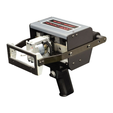
Telesis PINSTAMP TMP4100 Series Maintenance and service guide

Document No. 33480 Rev. D.01
Telesis Technologies, Inc. September 2003
28181 River Drive Change 1 – March 2004
P.O. Box 1000
Circleville, Ohio 43113
Installation/Maintenance
TMP4100-Series
PINSTAMP®Marking Head
This document contains installation and maintenance information
for the Telesis TMP4100 and TMP4100E hand-held markers and
the Telesis TMP4150 and TMP4155 fixture-mounted marking
heads. This document may be supplemented and kept current by
Change Notices and Revisions.


TMP4100-Series Installation/Maintenance
33480D01.DOC i
Change 1
List of Effective Pages
DATES OF MANUAL AND CHANGED PAGES:
First Issued.............................October 2000
Revision A.........................September 2001
Revision B................................... July 2002
Revision C...............................August 2002
Revision D.........................September 2003
Change D.01.............................March 2004
NOTE
The portion of the text affected by the change is indicated by a vertical line in
the outer margins of the page. Changes to illustrations (other than diagrams
and schematics) are identified with a miniature pointing hand. Shading is used
to highlight the area of diagrams and schematics containing a change.
This publication consists of the following pages:
("–" indicates original; integers indicate change)
PAGE CHG NO.
Title Page................................................ 1
i through iv.............................................. 1
v through viii .......................................... –
1-1 through 1-10..................................... –
1-11 through 1-12................................... 1
1-13 through 1-18................................... –
2-1 through 2-20..................................... –
2-21 through 2-22................................... 1
2-23 through 2-24................................... –
A-1 through A-10 ................................... –
INSERT LATEST CHANGED PAGES, DESTROY SUPERSEDED PAGES.
Those responsible for maintaining this publication should ensure that all
previous changes have been received and incorporated.

TMP4100-Series Installation/Maintenance
ii 33480D01.DOC
Change 1
This page intentionally left blank.

TMP4100-Series Installation/Maintenance
33480D01.DOC iii
Change 1
Foreword
Telesis Technologies, Inc. (hereinafter referred to as Telesis) reserves the right to change the information
and specifications contained in this document without prior notice. The reader should consult Telesis to
determine whether such changes have been made.
In no event shall Telesis be liable for any incidental, indirect, special, or consequential damages
whatsoever, including but not limited to lost profits, arising out of, or relating to this document or the
information it contains, even if Telesis has been advised, has knowledge, or should have knowledge of the
possibility of such damages.
Telesis expressly warrants the equipment it manufactures as set forth in the Standard Terms and Conditions
of Sale. Telesis makes no other warranties, expressed or implied, including and without limitation,
warranties as to merchantability or fitness for a particular purpose.
The information contained in this document is confidential and is proprietary to Telesis or its licensors.
All rights reserved. Printed in the U.S.A.
Copyright © 2000 – 2004 Telesis Technologies, Incorporated
Telesis and PINSTAMP are registered trademarks of Telesis Technologies, Incorporated.

TMP4100-Series Installation/Maintenance
iv 33480D01.DOC
Change 1
Safety Summary
The TMP4100-Series markers use high voltage power supplies and high pressure pneumatic supplies.
Accordingly, there is some danger when working with, and near, Pinstamp®marking machines. The
following safety precautions should be observed at all times.
♦Never use the marker in any manner or for any purpose other than that for which it was designed.
♦Eye protection may be required when working in close proximity of an operating marker.
♦Ear protection may be required when working with or near an operating marker.
♦Keep all body parts, jewelry, and clothing clear of the marker while it is operating.
♦Do not remove or defeat the marker’s safety features or protective guards.
♦TMP4100, TMP4150, TMP4155:Do not disconnect the tubing while air pressure is applied to the lines.
Warnings, Cautions, and Notes are placed throughout this document to alert you to important information.
These messages have the following significance.
WARNING
Warnings contain information that is essential to the personal safety of the user.
CAUTION
Cautions contain information that is essential to avoid damage to the equipment.
NOTE
Notes call attention to information of special importance at specific points within the text.

TMP4100-Series Installation/Maintenance
33480D01.DOC v
Table of Contents
PARAGRAPH PAGE
List of Effective Pages.......................................................................................................................... i
Foreword............................................................................................................................................... iii
Safety Summary.................................................................................................................................... iv
List of Illustrations................................................................................................................................ vii
List of Tables ........................................................................................................................................ vii
Section 1
Installation
1.1 Overview.................................................................................................................................. 1-1
1.2 Specifications........................................................................................................................... 1-2
1.2.1 TMP4100 Marking Head................................................................................................... 1-2
1.2.2 TMP4100E Marking Head ................................................................................................ 1-2
1.2.3 TMP4150 and TMP4155 Marking Heads......................................................................... 1-3
1.2.4 Filter/Regulator Unit.......................................................................................................... 1-4
1.2.5 Storage and Handling Requirements................................................................................. 1-4
1.3 Unpacking the Equipment........................................................................................................ 1-5
1.3.1 Accounting For Equipment ............................................................................................... 1-5
1.3.2 Inspecting for Damage....................................................................................................... 1-6
1.4 Installation Requirements ........................................................................................................ 1-6
1.4.1 General .............................................................................................................................. 1-7
1.4.2 Environmental Considerations .......................................................................................... 1-7
1.4.3 Marking Head.................................................................................................................... 1-7
1.4.4 Filter/Regulator Unit.......................................................................................................... 1-7
1.4.5 Facility (Supply) Air.......................................................................................................... 1-8
1.5 Installation Procedures............................................................................................................. 1-10
1.5.1 Marking Head Installation................................................................................................. 1-11
1.5.2 Filter/Regulator Unit Installation....................................................................................... 1-16
1.5.3 Controller Installation........................................................................................................ 1-17
1.5.4 Auxiliary Axis Equipment................................................................................................. 1-17
1.5.5 Installation Adjustments.................................................................................................... 1-17

TMP4100-Series Installation/Maintenance
vi 33480D01.DOC
Table of Contents
PARAGRAPH PAGE
Section 2
Maintenance
2.1 Overview .................................................................................................................................. 2-1
2.2 Maintenance Precautions.......................................................................................................... 2-1
2.3 Adjustment Procedures............................................................................................................. 2-1
2.4 Cleaning Procedures................................................................................................................. 2-2
2.4.1 Filter/Regulator Bowls....................................................................................................... 2-2
2.4.2 Impact Pin / Pin Cartridge.................................................................................................. 2-3
2.4.3 Marking Head Rail............................................................................................................. 2-3
2.5 Troubleshooting........................................................................................................................ 2-4
2.6 Testing Procedures ................................................................................................................... 2-10
2.6.1 Stepper Motor Resistance .................................................................................................. 2-10
2.6.2 Solenoid Resistance ........................................................................................................... 2-10
2.6.3 Extension Cable Continuity............................................................................................... 2-11
2.7 Repair Procedures..................................................................................................................... 2-12
2.7.1 Impact Pin Reconditioning................................................................................................. 2-12
2.8 Replacement Procedures........................................................................................................... 2-14
2.8.1 Impact Pin / Pin Cartridge.................................................................................................. 2-14
2.8.2 Marker Standoff................................................................................................................. 2-15
2.8.3 TMP4100 Solenoid Valve.................................................................................................. 2-16
2.8.4 TMP4100E Solenoid Valve ............................................................................................... 2-18
2.8.5 TMP4150 and TMP4155 Solenoid Valve.......................................................................... 2-20
2.9 Reference Data ......................................................................................................................... 2-21
2.9.1 Replacement Parts.............................................................................................................. 2-21
2.9.2 Ordering Parts.................................................................................................................... 2-23
2.9.3 Telesis Customer Support.................................................................................................. 2-23

TMP4100-Series Installation/Maintenance
33480D01.DOC vii
List of Illustrations
FIGURE PAGE
1-1 General Arrangement – TMP4100-Series Installation.................................................................. 1-10
1-2 TMP4100 and TMP4100E Dimensions........................................................................................ 1-13
1-3 TMP4150 and TMP4155 Mounting Details.................................................................................. 1-15
2-1 Cleaning the Filter/Regulator Bowl.............................................................................................. 2-2
2-2 Pin Cone Angle and Length.......................................................................................................... 2-12
List of Tables
TABLE PAGE
2-1 Troubleshooting the Marking Head .............................................................................................. 2-4
2-2 Stepper Motor Resistance Checks................................................................................................. 2-10
2-3 Solenoid Resistance Checks.......................................................................................................... 2-10
2-4 Marking Head Extension Cable Pin Assignments ........................................................................ 2-11
2-5 Impact Pin Lengths ....................................................................................................................... 2-12
2-6 TMP4100-Series Replacement Parts............................................................................................. 2-21
2-7 Cartridge Assemblies.................................................................................................................... 2-21
2-8 Cartridge Compression Springs .................................................................................................... 2-21
2-9 Impact Pins.................................................................................................................................... 2-22

TMP4100-Series Installation/Maintenance
viii 33480D01.DOC
This page intentionally left blank.

TMP4100-Series Installation/Maintenance
33480D01.DOC 1-1
Section 1
Installation
1.1 OVERVIEW
This section documents the installation of TMP4100, TMP4100E, TMP4150, and TMP4155 marking heads.
The TMP4100, TMP4150, and TMP4155 heads contain a pneumatic pin that uses air pressure to drive the pin
from and return the pin to the pin cartridge. The TMP4100E (electric) head uses no air pressure. The
TMP4100E uses an electric solenoid to drive and an internal spring to assist pin return.
Installation of the marking heads is almost identical. Where variation do exist, they will be clearly identified
within the text to inform you of the differences.
TMP4100, TMP4100E: The TMP4100 and TMP4100E markers are hand-held markers. They may be used in
any orientation except inverted (that is, with the handle pointing upward).
TMP4150, TMP4155: The TMP4150 and TMP4155 are fixture-mounted markers for in-line use. They may be
mounted in any orientation except inverted (that is, with the mounting holes pointing upward). Typically,
they should be mounted on a tooling fixture with the pin pointing downward. The TMP4150 and TMP4155
marking heads employ a protective boot to help prevent contaminants from entering the marking head cavity.

TMP4100-Series Installation/Maintenance
1-2 33480D01.DOC
1.2 SPECIFICATIONS
The marking equipment design and specifications are subject to change without prior notice.
1.2.1 TMP4100 Marking Head
Weight
1...................................... 4.08 lb. (1.85 kg) marking head with handle
5.50 lb. (2.50 kg) marking head with handle and marker cable
Dimensions (L x W x H) 2.............. 9.19 x 4.55 x 7.93 in. (234 x 116 x 201 mm) with 25XL pin & handle
9.44 x 4.55 x 7.93 in. (240 x 116 x 201 mm) with 150S pin & handle
X-axis Travel .............................. 2.0 in. (50 mm) maximum
Y-axis Travel .............................. 0.3 in. (7.6 mm) maximum
Number of Impact Pins............... 1
Pin Type...................................... 25XL- or 150S-series
Pin Material................................. Powered Metal or Carbide (25XL-series)
Powered Metal or Carbide-tipped (150S-series)
Pin Stroke: 25XL-series pin....... 0.125 in. (3.1 mm) recommended; 0.5 in. (12.7 mm) maximum
150S-series pin........ 0.125 in. (3.1 mm) recommended; 0.25 in. (6.35 mm) maximum
Air Consumption
3
At Idle.............................. 0.04 SCFM maximum
While Marking................. 0.80 SCFM maximum
Operating Temperature............... 32° to 122°F (0° to 50°C)
Humidity..................................... 0% to 80%
1.2.2 TMP4100E Marking Head
Weight
1...................................... 4.08 lb. (1.85 kg) marking head with handle
5.50 lb. (2.50 kg) marking head with handle and marker cable
Dimensions (L x W x H) 2.............. 9.91 x 4.55 x 7.93 in. (252 x 116 x 201 mm) with 25XLE pin & handle
X-axis Travel .............................. 2.0 in. (50 mm) maximum
Y-axis Travel .............................. 0.3 in. (7.6 mm) maximum
Number of Impact Pins............... 1
Pin Type...................................... 25XLE
Pin Material................................. Carbide
Pin Stroke.................................... 0.187 in. (4.7 mm) maximum
Operating Temperature............... 32° to 122°F (0° to 50°C)
Humidity..................................... 0% to 80%
Notes:
1) Weight listed includes 25XLE carbide pin and pin cartridge.
2) Length may slightly exceed dimension listed due to bend radius of marker cable and, if applicable, air line
3) Air consumption is dependent on the type of pin being used.

TMP4100-Series Installation/Maintenance
33480D01.DOC 1-3
1.2.3 TMP4150 and TMP4155 Marking Heads
Weight
1.......................................8.7 lb. (3.9 kg) marking head, brackets, and cable
Dimensions (L x W x H) 2..............9.89 x 5.12 x 4.96 in. (251 x 130 x 126 mm) with 25XL pin (w/o boot*)
10.14 x 5.12 x 4.96 in. (258 x 130 x 126 mm) with 150S pin (w/o boot*)
Boot Material...............................TMP4150: Neoprene
TMP4155: Nitrile (synthetic rubber)
* Boot Dimension...........................5.33 in. (135 mm) diameter
X-axis Travel...............................2.0 in. (50 mm) maximum
Y-axis Travel...............................0.3 in. (7.6 mm) maximum
Number of Impact Pins................1
Pin Type ......................................25XL- or 150S-series
Pin Material.................................Powered Metal or Carbide (25XL-series)
Powered Metal or Carbide-tipped (150S-series)
Pin Stroke: 25XL-series pin........0.125 in. (3.1 mm) recommended; 0.5 in. (12.7 mm) maximum
150S-series pin.........0.125 in. (3.1 mm) recommended; 0.25 in. (6.35 mm) maximum
Air Consumption
3
At Idle ..............................0.04 SCFM maximum
While Marking.................0.80 SCFM maximum
Operating Temperature................32° to 122°F (0° to 50°C)
Humidity......................................0% to 80%
NEMA Rating..............................12 (I.P. 55)
Notes:
1) Weight listed includes 25XL carbide pin and pin cartridge; weight does not include any support tooling.
2) Dimensions without marker cable or air line.
Length may slightly exceed dimension listed due to bend radius of marker cable and air line (if applicable).
3) Air consumption is dependent on the type of pin being used.

TMP4100-Series Installation/Maintenance
1-4 33480D01.DOC
1.2.4 Filter/Regulator Unit
TMP4100E: The TMP4100E does not employ a filter/regulator unit. It uses an electric solenoid to drive the
pin and an internal spring to assist pin return.
TMP4100: The filter/regulator unit includes a regulator with a coarse filter and a pressure gauge to control the
drive air. The unit also includes a coalescing filter to remove finer particles. The drive air fires the pin from
the cartridge.
TMP4150, TMP4155: The filter/regulator unit includes two regulators with pressure gauges to control the drive
air and return air. The first regulator contains a filter to help remove contaminants from the supply air. The
drive air fires the pin from the cartridge. The return air pushes the pin back into the cartridge.
Temperature............................32° to 122°F (0° to 50°C)
Operating Pressure..................120 psi (8.3 bars) maximum
1.2.5 Storage and Handling Requirements
Do not drop the containers.
Shock......................................75G/11ms half sine-wave
Vibration.................................1.04G (2-200 Hz) random RMS
Store all containers in a dry, heated, non-condensing environment.
Temperature............................-4° to 113°F (-20° to 45°C)
Humidity.................................5% to 95%
Store all containers away from splashing or sprayed moisture.

TMP4100-Series Installation/Maintenance
33480D01.DOC 1-5
1.3 UNPACKING THE EQUIPMENT
This section provides guidelines for receiving and unpacking the TMP4100-Series marking equipment.
CAUTION
If your equipment arrives during cold weather, allow the components to
warm up for several hours before opening the containers. Exposing the
equipment to room temperatures may cause condensation in the units.
When your marking equipment arrives, check the shipping cartons for damaged corners, holes through the
cardboard, or any other signs of damage. Ask the delivery service to note any damage to the containers on the
delivery receipt. Save all packing materials in case you need to return any components.
1.3.1 Accounting For Equipment
Check the materials against the packing list. Note any discrepancies to your delivery service and request that
they note the discrepancies on the delivery receipt. The marking equipment consists of:
•TMP4100, TMP4100E: Marking head with pre-attached pistol-grip handle
•TMP4150, TMP4155: Marking head with mounting plate.
•Marker cable (pre-wired to head)
•TMP4100, TMP4150, TMP4155: Filter/regulator unit
•TMP4100, TMP4150, TMP4155: Air line(s)
Additional components may be included with the marking equipment. Specific information for optional
equipment may be provided in a separate installation manual. Specific information for custom equipment
may be provided in a custom addendum.

TMP4100-Series Installation/Maintenance
1-6 33480D01.DOC
1.3.2 Inspecting for Damage
Place the components on a table and inspect each one for damage. Report any damage to your delivery service
immediately.
1. Inspect the marking head.
♦Ensure the marking head is not dented or cracked.
♦TMP4100, TMP4100E: Visually inspect the interior of the marking head for loose, disconnected, or
broken components.
♦TMP4100, TMP4100E: Visually inspect the front of the marking head for any debris that may restrict
movement.
♦TMP4100, TMP4100E: Inspect the pistol-grip handle and push-button for cracks and damage.
♦TMP4150, TMP4155: Inspect the protective boot for tears, cuts, or damage and for security of
attachment.
2. Inspect the impact pin and pin cartridge.
♦Ensure the impact pin is not bent or broken.
♦Ensure the pin cartridge is not cracked or broken.
3. Inspect the cable assemblies.
♦Ensure the connectors are securely attached.
♦Ensure the connectors are not damaged and the connector pins are not bent or broken.
♦Ensure the electrical cables are not cut, frayed, or damaged.
4. Inspect the filter/regulator unit.
♦TMP4100, TMP4150, TMP4155: Ensure the fitting threads are not damaged.
♦TMP4100, TMP4150, TMP4155: Ensure the pressure gauge(s) and bowls are not cracked.
5. Inspect the air line(s).
♦TMP4100, TMP4150: Ensure the air line(s) are not kinked, cracked, or damaged.
1.4 INSTALLATION REQUIREMENTS
TMP4100, TMP4100E: These marking heads are to be used as hand-held markers.
TMP4150, TMP4155: These marking heads are to be mounted on a tooling fixture. If the marker is to be
incorporated into a machine or mounted on a tool stand, safeguards must be designed and implemented at the
time of the installation with the other machinery.
If the marker includes custom equipment, refer to the custom Addendum for specific information.
The following items are required for proper installation of the marking head. It is the responsibility of the
installing agency to ensure these requirements are implemented.

TMP4100-Series Installation/Maintenance
33480D01.DOC 1-7
1.4.1 General
•TMP4150, TMP4155: A safety guard may be required to keep operators away from the moving marking
head and impact pin.
•TMP4150, TMP4155: A part-present switch may be installed to allow a START PRINT only when a part is
in marking position.
•Operators may need hearing protection depending on distance from the marker and the part to be marked.
•Operators may need eye protection while operating the marker.
1.4.2 Environmental Considerations
•TMP4100, TMP4100E: The marker should not be exposed to sprays, solvents, chemicals, or other
contaminants.
•TMP4150, TMP4155: These markers may be exposed to light sprays, solvents, chemicals, or other
contaminants.
•Do not operate the marker in an area where flammable mists or fumes are present.
•Certain chemicals may damage the exposed portion of the cartridge.
1.4.3 Marking Head
•The marking head should be visible from the controller. The standard marker cable is 4 m (13 ft.) long.
•TMP4150, TMP4155: Provisions should be made to allow vertical adjustments to the marking head,
allowing the marker to be positioned closer to and further away from the part being marked.
•TMP4150, TMP4155: Provisions should be made to allow horizontal and lateral adjustments to the
marking head, allowing the marker to be positioned along both the X-axis and the Y-axis.
•TMP4150, TMP4155: The marking head can be plumbed to receive internal air pressure. Positive air
pressure within the marker will help prevent contaminants from entering the marking head cavity.
Never exceed an internal air pressure of 2.0 psi (0.13 bars) within the marking head.
•The part to be marked must be solidly fixed into position.
•The marker must be solidly secured (or held) and must not move in relation to the part while marking.
1.4.4 Filter/Regulator Unit
TMP4100E: The TMP4100E does not use air pressure to drive the marking pin. The following section does
not apply to the TMP4100E marker.
TMP4100, TMP4150, TMP4155: The filter/regulator unit inlet receives air pressure from the plant air source.
The drive air outlet supplies air pressure to the marker to drive the marking pin out of the pin cartridge for
marking. Return air pressure retracts, and holds, the pin in the cartridge. For TMP4100 markers, the marking
head contains an internal regulator to control the return air. For TMP4150 and TMP4155 markers, the return
air is controlled by a separate regulator on the filter/regulator unit.
•The filter unit should be installed within 12 ft. (3.6 m) of the marking head; 50 ft. (15 m) maximum.
•A pneumatic lockout valve (supplied by the customer) should be installed upstream of the filter unit.
•A pressure relief valve (supplied by the customer) should be installed upstream of the filter unit.
•The pressure relief valve must be set to a maximum pressure of 120 psi (8.3 bars).
•Do not connect the filter unit to air systems where compressors are lubricated with fire resistant fluids
such as phosphate ester and di-ester types.

TMP4100-Series Installation/Maintenance
1-8 33480D01.DOC
•If the supply air is extremely dirty, additional customer-supplied filters may be needed upstream of the
filter unit.
•The filter unit must be located to allow servicing and draining without damaging other equipment.
•Do not install the filter unit in an area subject to direct sunlight, impact blows, or extreme temperatures.
•Do not install the filter unit where it will be exposed to aldehydes, keytones, alcohol, or hot water.
•Install the regulator so the air flows in the direction of the arrow on the body of the filter unit.
•The filter unit bowls must be mounted vertically with the bowl drains at the bottom to permit draining.
•Each port of the filter unit must be plumbed (e.g., pressure gauge, line fitting, socket pipe plug).
•The customer-furnished supply line to the filter unit should be 1/2-in. (13 mm) inside diameter.
•The filter unit requires a 1/4-in. (6 mm) NPT supply air inlet fitting (supplied by customer).
•Apply a minimal amount of pipe joint compound to the male threads (only) to seal the pipe joints.
•Do not use Teflon®tape to seal the pipe joints. Do not apply pipe joint compound to female threads.
1.4.5 Facility (Supply) Air
TMP4100E: The TMP4100E does not use air pressure to drive the marking pin. The following section does
not apply to the TMP4100E marker.
TMP4100, TMP4150, TMP4155: The marking head requires a clean, dry air supply to drive the impact pin. In
most cases, plant air is acceptable. The following guidelines should help you decide if your air supply is
suitable for use with the marker.
Condensation. The process of compressing air creates heat. The compressed air cools as it travels through the
lines away from the compressor. The cooling process causes any moisture in the air to condense.
Condensation is common in hot climates or when air lines are routed outside during cold weather.
Condensation creates problems in the air valves and small openings within the marking head. Because you
can never remove all the contaminates from an air line, a filtering system should be installed as close to the
marker as possible. This reduces the opportunity for moisture in the supply air to condense.
Filtering. The least expensive way to filter the air is to use a coalescing filter. This type of filter causes a
cyclone effect. Swirling air and the resulting centrifugal force throws the oil and moisture particles to the
outside. There it condenses on a wall and runs down to the bottom of the bowl in the less turbulent, quiet area.
The coalescing filter removes solid particles (down to 0.3 microns). If the collection of contaminants becomes
too great, particles can be picked up and placed in suspension in the air. Therefore, Telesis recommends an
automatic drain on the coalescing filter. In addition to aerosol particles, the air may contain dust, dirt, and
metal shavings. If the air is very dirty, a pre-filter can be used to remove the larger (5 micron) particulate
matter.
Air Flow. The cyclone effect (see above) cannot occur if there is little or no flow of air. Telesis markers use
much less air at idle than when marking. So it’s during the idle time that the aerosol particles have a chance to
cool and condense on the walls of the cartridge and pin. Most filter manufactures recommend a minimum air
flow of 20% of the maximum rated flow for their equipment to be effective. This is not a problem during
marking because the rate of air consumption is relatively high. A controlled orifice opening (open to the air)
can be constructed to keep the flow during idle at or above 20% of the flow rate. The controlled orifice should
be located as close as possible to the marking head.

TMP4100-Series Installation/Maintenance
33480D01.DOC 1-9
Plumbing Factors. Another practice for obtaining clean,
dry air is to ensure the equipment is not at the end of the
air line. Plumb the air supply to go up (vertically) off the
main air supply line, then down to the top of a tee. The
stem of the tee should be horizontal and go to the
marker. The bottom of the tee should be a short stub with
a drain valve or drip leg.
Parameters. The following parameters are easily achievable with a pre-filter and most coalescing filters.
•Humidity non-condensing
•99.97% of the sub-micron particles removed
•0.75 micron largest aerosol particle
•0.30 micron largest solid particle
•40° to 120°F (4.4° to 48.9°C)
•5 micron pre-filter with an auto drain.
Practices. Follow these practices when installing and operating the marker to improve the quality of the air
and increase the reliability of your marking equipment.
•Install the filter as close as possible to the marking head, never more than 50 ft. (15 m)
•Use Polyflo® tubing downstream of filter with brass or plated fittings
•Use copper, brass or stainless tubing upstream of the filter
•Do not use iron pipe or iron fittings.
•Do not use Teflon®tape
•Liquid Teflon®is permissible except:
– on poly-carbonate plastic threaded holes
– on the first thread of male fittings
•Blow down the air system after installation and before use (at least two minutes at full flow).
•Use a top tap off the main line with a drip leg (see Plumbing Factors).
•Do not use poly-carbonate bowls (they will crack when used with synthetic oils).
•Always use the largest available feed line and the shortest available run.

TMP4100-Series Installation/Maintenance
1-10 33480D01.DOC
1.5 INSTALLATION PROCEDURES
Perform the following procedures (in the order listed) to install the marking equipment.
See Figure 1-1 for a general arrangement illustration.
NOTE
It is the responsibility of the installing agency to ensure the installation
requirements are correctly implemented.
Figure 1-1. General Arrangement – TMP4100-Series Installation
This manual suits for next models
4
Table of contents
Other Telesis Industrial Equipment manuals
