A##C & A##S
A SERIES ELASTOMERIC COUPLINGS
Fitting & Maintenance Instructions
2
Preparation
John Crane’s Powerstream couplings are available in many sizes and types. Check prior to any installation that the correct parts are on hand and as
ordered. Type A close-coupled couplings include two close-coupled hubs (with lug extensions), flexible insert, retaining ring and setscrews. Type A
spacer couplings include one close-coupled hub (with lug extensions), one hub (flanged), spacer, bolts with washers, flexible insert, retaining ring and
setscrews. Inspect all components and remove any protective coatings from the bores, etc. Remove any burrs or dirt from the shafts or bores.
Storage
If the coupling is not to be used immediately, it should be stored away from direct heat in its original packing. All documentation supplied with the
coupling should be retained for future reference.
Spares
When requesting spares, always quote the full designation of the coupling. The following spares can be purchased from John Crane:
• Flexible inserts (ref. 1) • Spacer (ref. 5)
• Retaining ring with setscrews (ref .3, 4) • Set of stripper bolts (ref. 7)
• Hubs, bored to your requirement or unbored (ref. 2, 6)
Installation
Remove coupling from packaging and carefully inspect for signs of damage. Pay particular attention to the hub bores and the pilot/recess location
features, which should be free from burrs and other damage.
Installation of hubs
Prior to installing the coupling, ensure that the machinery is made safe. Hubs must be adequately supported during
installation to avoid accidental damage should they slip.
1. Ensure the hub bore and mating shaft are clean.
2. Determine the fit required for your application (i.e. clearance or interference). The hubs are suitable for both interference and clearance fits. For
interference fits, we recommend heating the hubs in oil or an oven and quickly positioning on shafts (do not use spot heat or exceed 350˚F / 175˚C
as this may cause hub distortion). Shaft ends should be flush with the hub face at bottom of lug extensions unless longer or shorter than standard
distance between shaft ends (DBSE) is planned for. In which case, refer to drawing indicating the amount that the hubs should be mounted offset
from the shaft ends in order to obtain dimension E (see alignment).
3. Tighten setscrews when clearance fits are used or tighten screws when using intermediate bushings.
A Series close-coupled type C
• Fit the first close-coupled hub as above and slip the retaining ring (3) over the installed hub.
• Fit the second close-coupled hub.
A Series spacer type S
• Fit the first close-coupled hub as above and slip the retaining ring (3) over the installed hub.
• Fit the flanged hub (6). Shaft end should be flush with the hub face.
• Supporting the spacer (5), locate the spacer flange to the hub pilot and insert the stripper bolts (7)
and tighten evenly to the tightening torque in Table 1.
IMPORTANT Prior to installation of a second close-coupled hub or spacer, make sure the retaining ring is placed over the hub or shaft.
TABLE 1. Tightening Torque for Spacer Hub Stripper Bolts
Coupling Bolt Size Nm lb.ft Spanner A/F Allen Key (Hex. Socket)
A01S M8 19 14 13 mm -
A02S M8 19 14 13 mm -
A03S M10 54 40 - 8 mm
A04S M12 100 74 - 10 mm
A05S M12 100 74 - 10 mm
A06S M16 232 171 - 14 mm
FIGURE 2.
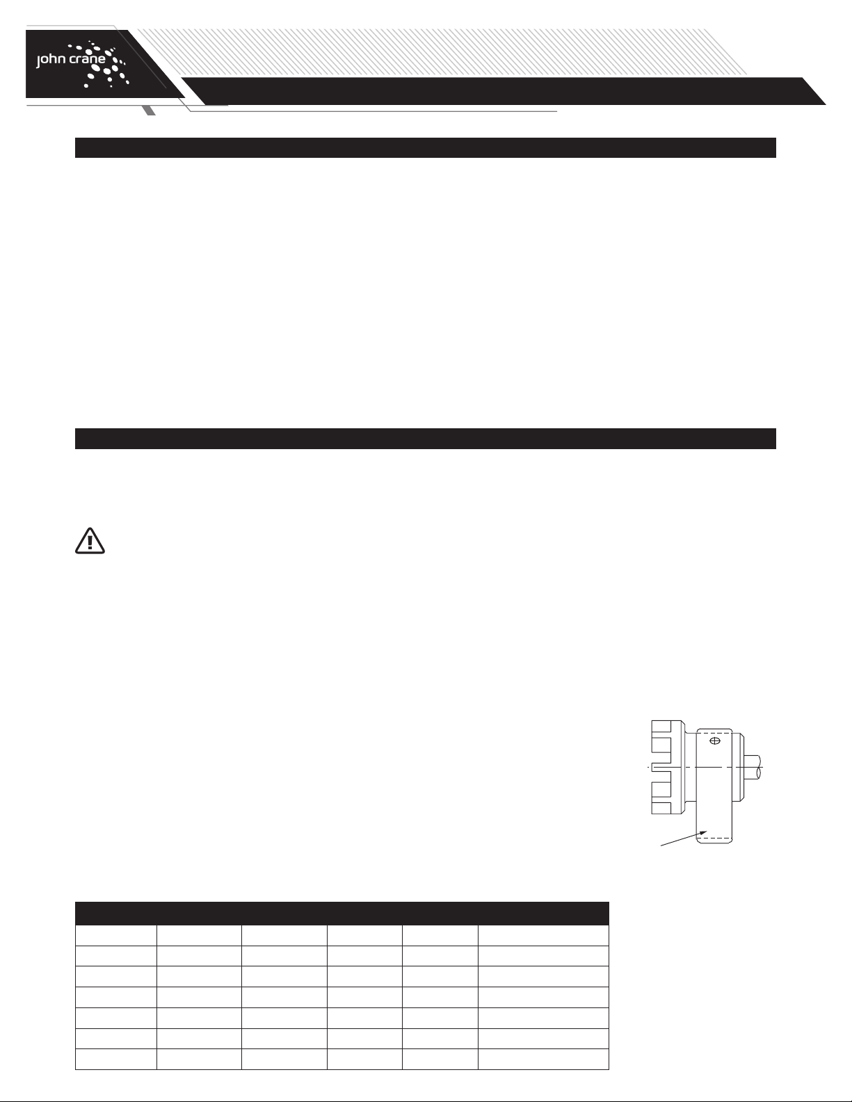
Retainer Ring Installation
Retaining
Ring


