Tone NITRO Guide

INSTALLATION AND USER INSTRUCTIONS
AUGUST 2021
VERSION 2.0
INSTA
DIGITAL MANUAL

DISCLAIMER
Congratulations on purchasing your new TONE product. The information in this
document affects your safety and your legal rights and responsibilities. Read this
entire document carefully to ensure proper configuration before use. Failure to read
and follow instructions and warnings in this document may result in serious injury to
yourself or others, damage to your TONE product, or damage to other objects in the
vicinity. This document and all other collateral documents are subject to change at the
sole discretion of TONE. For up-to-date product information, visit http://www.tone-
swiss.com and click on the product page for this product.
By using this product, you hereby signify that you have read this disclaimer and warning
carefully and that you understand and agree to abide by the terms and conditions
herein. You agree that you are solely responsible for your own conduct while using
this product, and for any consequences thereof. You agree to use this product only
for purposes that are proper and in accordance with all applicable laws, rules, and
regulations, and all terms, precautions, practices, policies and guidelines TONE has
made and may make available.
TONE accepts no liability for damage, injury or any legal responsibility incurred directly
or indirectly from the use of this product. The user shall observe safe and lawful
practices including, but not limited to, those set forth in this document.
Copyright © 2021 by TONE Kaffeemaschinen AG
All rights reserved. No part of this publication may be reproduced, distributed, or
transmitted in any form or by any means, including photocopying, recording, or other
electronic or mechanical methods, without the prior written permission of the publisher.
For permission requests, write to the publisher, addressed at the address below.
TONE Kaffeemaschinen AG
Rheinweg 4
8200 Schaffhausen
Switzerland
+41 52 620 06 06
contact@tone-swiss.com
www.tone-swiss.com

1. INTRODUCTION / GENERAL
2. SAFETY REGULATIONS
3. REQUIREMENTS FOR THE LOCATION OF OPERATION
4. DESCRIPTION OF THE DEVICE
5. INSTALLATION
1.1 General
1.2 Unpacking the device
1.3 Mode of Operation
1.4 Requirements for the beverages
1.5 Technical specification
1.6 Declarations
2.1 General safety regulations
2.2 Electrical hazard
2.3 Operating overpressure
2.4 Danger due to operational cooling
2.5 Danger due to operational heating up
2.6 Danger from sheet edges
2.7 Danger due to flammable refrigerant
3.1 General requirements
3.2 Electrical connections
3.3 Location of operation
4.1 Graphic illustration of the device
4.2 Graphic illustration “NITRO CONTROL PANEL”
4.3 Graphic illustration “SUCTION HOSE”
4.4 Graphic illustration “CLEANING SET”
4.5 Graphic illustration “DRIP TRAY”
4.6 Scope of delivery
5.1 Assembly of the PERLATOR-UNIT
5.2 Assembly of the TAP-UNIT
5.3 First time installation
5.4 Connection of the SUCTION HOSE
5.5 Switching on the device / Ready for operation
5.6 Setting the NITRO effect / foaming
5.7 NITRO or PURE-mode
5.8 Setting the cooling
5
7
8
8
8
9
9
12
9
12
9
12
10
12
10
13
10
14
11
14
15
15
5
7
6
8
5
7
6
8
6
8
7
8
8
TABLE OF CONTENS

6. HYGIENE AND CLEANING
7. MAINTENANCE
8. TECHNICAL DOCUMENTATION
9. TROUBLESHOOTING
EG DECLARATION OF CONFORMITY
6.1 Hygienic handling
6.2 Cleaning schedule
6.3 Equipment areas to be cleaned
6.4 Approved cleaning agents
6.5 Preparation / Switch off machine and remove TAP UNIT
6.6 Cleaning of the TAP UNIT
6.7 Cleaning the PERLATOR UNIT and the MIXER HOUSING
6.8 Preparation of the cleaning liquid
6.9 Dry cleaning
6.10 Empty liquid from device
7.1 Cleaning
7.2 O-rings, Perlators and tap unit
7.3 Air filter
7.4 Condenser fins
8.1 Exploded drawing
8.2 Flow diagram
8.3 Circuit diagram
8.4 Electrical assembly compressor
16
22
23
27
25
16
22
23
22
24
23
24
23
24
16
17
17
18
18
19
20
21
21

05
1. INTRODUCTION / GENERAL
1.1 GENERAL
This manual provides essential information
for safe operation of your NITRO dispensing
system / cold beverage processing system.
Please therefore read the enclosed safety
instructions carefully.
This applies in particular to safety during
installation, operation and cleaning. Please
keep this manual in a safe place
where it is accessible to all users.
Errors and technical changes reserved.
The TONE Kaffeemaschinen AG (in ac-
cordance with its policy) is constant-
ly developing the products further. The
TONE Kaffeemaschinen AG therefore
reserves the right to make changes and im-
provements to the product described in this
documentation without prior notice.
Reproduction of any kind without the prior
written permission of TONE Kaffeemaschin-
en AG is strictly prohibited. All other brands
and names mentioned in this documenta-
tion refer to the corresponding companies
or their products. TONE Kaffeemaschinen
AG claims no right of ownership of brands
or names other than its own.
Disclaimer: Despite careful control of the
contents, TONE Kaffeemaschinen AG ac-
cepts no liability for the content of external
links. The operators of the linked sites are
solely responsible for the content of their
sites.
Please read the operating instructions care-
fully before use and keep them in a way that
they are accessible to all users!
WARNING SIGN
ATTENTION!
MANDATORY SIGN!
PLEASE READ IT.
INFORMATION SIGN!
INFORMATION.
1.2 UNPACKING THE DEVICE
WARNING!
Check immediately whether
any damage can be seen on
the outer packaging of the
device.
Check immediately whether any
damage can be seen on the outer
packaging of the device. Immediately
report any damage to the transporter
or contract partner and document it.
If you do not do this as an entrepreneur,
the goods will be considered
„approved“ and the recipient will no
longer be able to rely on the transport
damage later.
After you have carefully unpacked the
device, please check whether the device has
any external damage.
Keep the packaging in case the device
may have to be shipped by a forwarding
agent. The packaging materials (boxes,
plastic bags) must never be allowed
to fall into the hands of children.
If any defects or damage to the device
are found, please inform the dealer
where you purchased the device
immediately so that the matter can be
dealt with.
INTRODUCTION / GENERAL

06
1.3 MODE OF OPERATION
This cold beverage processing system
combines various functionalities in one
device:
▪ Designed for bag-in-box applications/
sucking a beverage from a pressureless
container
▪ Vacuum switch switches off automatically
when the bag-in-box is empty
▪ Designed for Cold Brew Coffee and certain
other beverages. Suitable for operation with
air, nitrogen and CO2 and adjustable via
„NITRO CONTROL PANEL“ on
the unit or external gas supply
▪ Enrichment of the drink with atmospheric
nitrogen (78%)
▪ Cooling the beverage in the appliance
Cooling block
▪ Tapping the drink in stout-style
1.4 REQUIREMENTS FOR THE
BEVERAGES
WARNING!
The liquids must be filtered
to a filtration grade of at
least 100 µm!
This device was primarily developed
for use with Cold Brew Coffee. However,
use with other beverages such as tea is
also possible if guidelines are followed.
The liquids used must be consumable
liquids. High-proof spirits, syrups
as well as not filtered liquids are
forbidden. It is essential to note that
the liquids must be filtered to a filtration
grade of at least 100 µm (100 microns)
(cf. common disposable filters made of
filter paper), otherwise the pump inside the
device or the PERLATOR UNIT may become
clogged and the device will be damaged.
Furthermore, it should be noted that it is
essential to clean the device after use with
fresh beverages. Only when used with
pasteurized beverages do other cleaning
intervals apply.
Read „CLEANING PLAN AND
INTERVAL“ for information on cleaning-
related issues. Non-compliance will
void the warranty!
1.5 TECHNICAL SPECIFICATION
Produkt / Product:
Typ / Type:
Baujahr / Date of manufacture:
Klimaklasse / Climate class:
Kühlmittel / Refrigerant:
Masse/ Weight:
Serien-Nr. / Serial - No.:
1/N/PE AC 230 V 50 Hz 1,6 A
Getränkezubereitungssystem /
Beverage preparation system
TONE NITRO
2021
N
R290 (50g)
24 kg
TONE-2021-30-1001
SCHULTES MASCHINENBAU GMBH
Am Beetacker 5
63856 BESSENBACH,
DEUTSCHLAND
The weight refers to the machine without
attachments.
WIDENECK
CANISTER
FLEXIBLE
CANISTER
MODE OF OPERATION

07
DECLARATIONS
1.6 DECLARATIONS
We declare under its sole responsibility
that the product „NITRO 2.0“ to which
this declaration refers, complies with the
following directive(s) and standard(s):
LIST OF TECHNICAL REGULATIONS:
• Richtlinie 2006/42 / EG -
Maschinenrichtlinie
• Richtlinie 2014/30 / EU -
Elektromagnetische Verträglichkeit
(EMV)
• Richtlinie 2011/65 / EU - Beschränkung
gefährlicher Stoffe (RoHS)
• NSP-Richtlinie neu 2014/35/EU
All parts in contact with the
medium/liquid and sealants
used in this device comply with
the requirements of the FDA
(Food and Drug Administration) and/or are
made of stainless steel.
2. SAFETY REGULATIONS
2.1 GENERAL SAFETY REGULATIONS
This device corresponds to
the current state of the art.
Operational safety is only
guaranteed if the operating
instructions are followed.
Work instructions must be
followed taking into account the following
dangers.
During the installation and operation of the
NITRO dispensing system we also point out
that the following relevant laws, ordinances,
guidelines and regulations must be observed
and complied with:
1. Equipment and product safety law - GPSG
2. Occupational Safety and Health Act -
ArbSchG
3. Industrial safety ordinance - BetrSichV
4. Food hygiene regulation – LMHV
5. Beverage Dispensing Systems Ordinance
- SchankV (until 30.06.2005)
6. Technical rules for beverage dispensing
systems (TRSK and DIN standards)
7. Ordinance on Hazardous Substances
(Gefahrstoff V)
8. Generally accepted rules of technology
Relevant country-specific rules, guidelines
and regulations are to be applied.
Conversions or changes to safety-relevant
components or elements are generally
prohibited and automatically lead to the
expiration of the manufacturer‘s warranty.
▪ Check the device at least once a day
for visible damage and defects. Contact
a qualified service technician if you need
to make any changes or repair work. The
power cord may only be replaced by
authorized service personnel. Use only
original spare parts and accessories.
▪ Make sure that only authorized
personnel work on the device and that
the operating personnel is provided with
operating instructions and this user manual.
▪ Make sure that no unauthorized person
changes settings on the device or interferes
with the device.
We accept no liability for damage resulting
from the use of non-original spare parts
or accessories, as well as from improper
handling or use outside the device‘s
intended purpose.
2.2 ELECTRICAL HAZARD
Electric shock can be fatal or
lead to serious injury!
Unauthorized interference
with the electrical system is
therefore strictly prohibited.
Water and electricity
produce a deadly mixture!

08
OPERATING OVERPRESSURE
The device is supplied with a moulded
safety plug and may only be connected
to a grounded safety socket. If there is no
corresponding socket outlet with earthing
contact, the connection may only be carried
out by authorised personnel, whereby the
regulations valid at the place of installation
(e.g. in Germany VDE-DIN standard) must
be observed.
2.3 OPERATING OVERPRESSURE
Some components are under
overpressure during
operation and are therefore
a potential source of danger.
Do not loosen or dismantle
any parts that are under
excess operating pressure.
2.4 DANGER DUE TO OPERATIONAL
COOLING
The evaporation temperature
in the coolant circuit can be
as low as -10°C. There is
therefore a potential source
of danger if maintenance,
servicing, cleaning etc. are
carried out on components at the
appropriate temperature without suitable
protective measures.
2.5 DANGER DUE TO OPERATIONAL
HEATING UP
Do not touch the compressor,
condenser, motors and
piping and in particular the
radiator grille on the rear of
the device, as these parts
can heat up during operation,
which may cause injury if touched.
2.6 DANGER FROM SHEET EDGES
There is a residual risk of
injury at sheet edges and
corners despite constructive
prevention.
2.7 DANGER DUE TO
FLAMMABLE REFRIGERANT
The unit is filled with 50g of
flammable refrigerant
(R290). Due to the design
and other precautions, the
risk of flammability can be
excluded as far as possible.
3. REQUIREMENTS FOR THE LOCATION
OF OPERATION
3.1 GERNERAL REQUIREMENTS
Please also observe the technical
regulations for beverage dispensing
systems TRSK 400 „Installation of
beverage dispensing systems“.
Low voltage can damage the compressor.
The same applies if several units are
supplied with power via one power
connection.
The power plug must be freely
accessible.
3.2 ELECTRICAL CONNECTIONS
(see 1.6 Technical specification)
FUSE PROTECTION:
max. 1,6 A
VOLTAGE:
1/N/PE AC 230 V 50 Hz 1,6 A
POWER: 300 W

9
LOCATION OF OPERATION
3.3 LOCATION OF OPERATION
Adequate ventilation and extraction must
be ensured. For this purpose the distance
to the next wall should be at least 20 cm.
Attention:
▪ Never cover and/or block
the air slots. Otherwise
there will be insufficient
cooling capacity and the
cooling system may fail.
▪ Never place the device near
heat sources or direct sunlight.
▪ Under no circumstances should liquid
enter the device, otherwise there is a danger
of short circuit!
4. DESCRIPTION OF THE DEVICE
4.1 GRAPHIC ILLUSTRATION OF
THE DEVICE
These instructions are valid for all
variantes of the NITRO 2.0 Series.
NITRO 2.0
MIXER HOUSING
NITRO CONTROL
PANEL
HANDLE
TAP
BEVERAGE
CONNECTION
POWER CABLE
COOLING GRILL
4.2 GRAPHIC ILLUSTRATION
“NITRO CONTROL PANEL”
NITRO 2.0
1
5
6
4
2
7
3
1
2
3
4
5
6
7
NITRO-SWITCH ON/OFF
NITRO CONTROL DIAL
COOLING CONTROL DIAL
DEVICE SWITCH ON /OFF
1
2
4
5
1
2
4
5

10
4.3 GRAPHIC ILLUSTRATION “SUCTION HOSE”
4.4 GRAPHIC ILLUSTRATION “CLEANING SET”
4.5 GRAPHIC ILLUSTRATION “DRIP TRAY”
NC PLUG-IN CONNECTOR
SCREW CONNECTION WITH WING NUT
DRIP TRAY “SMALL”
CLEANING CANISTER
CONNECTOR
UNION NUT
CLEANING POWDER
CLEANING BALL
CLEANING BRUSH
1
2
3
4
5
6
6
4
2
5
3
1
2
1
1
1
1
2

11
SCOPE OF DELIVERY
Article No Name Description
TO-103010 PERLATOR-UNIT
PERLATOR-UNIT CONSITING OF:
1X TO-103011-FRONT-PERLATOR A “GREEN”
1X TO-103012-MIDDLE-PERLATOR B “GREEN”
1X TO-103013-END-PERLATOR C “GREEN”
TO-108010 O-RING SET
(ALL)
SPARE O-RING SET CONSITING OF:
1X SEALING RING FOR SUCTION HOSE (TRANSPARENT)
4X O-RING PERLAOT UNIT (RED)
2X O-RAING PERLAOT UNIT (BLACK)
TO-104014 HANDLE HANDLE
TO-105010 SUCTION HOSE
WITH NC/CMB -
CONNECTION
SUCTION HOSE FOR NITRO WITH NC/CMB CONNECTION,
2M LENGHT
TO 106018 DRIP TRAY
“NITRO” DRIP TRAY FOR NITRO DISPENSING SYSTEM, SMALL
TO-103010 QUICKMANUAL QUICK START GUIDE LAMINATED IN PROTECTIVE FOIL;
TO-107010 CLEANING
POWDER
3X PACKAGS RELIABLE QUALITY CLEANER WITH ACTIVE
OXYGEN FOR REGULAR
ALKALINE CLEAINING;
TO-106010 CLEAINING
CANISTER 5L FOLDING CLEANING CANISTER WITH 5L CAPACITY AND NC
NC/CMB - CONNECTION
TO-107014 CLEANING BALL BEVI CLEAN BALL, TRANSPARENT THROUGHOUT, NO GAPS
AND VALVES, FOR INTERIOR AND EXTERIOR CLEANING
TO-107015 CLEANING
BRUSH CLEANING BRUSG FOR CLEANING THE MIXER HOUSING
4.6 SCOPE OF DELIVERY

12
INSTALLATION
5. INSTALLATION (STEP BY STEP)
5.1 LOCATION OF OPERATION
2
Front-Perlator A (incl. 2 x black O-rings)
Middle-Perlator B (3 pcs.)
End-Perlator C (has two grooves)
Attention:
Pay attention to the O-rings!
These are located in a groove
on the front and rear side of
the FRONT PERLATOR A!
A ventilated perlator does not present
a significantly increased risk of aerosol
formation. The supplied nitrogen is
sufficiently cleaned by air filters.
To prevent the perlators from being
contaminated with biofilm growth, the
individual perlators (Perlator - A „green“,
!
Perlator - B „green“, Perlator - C „green“)
must be cleaned after use. In addition, the
inserts (103019 Perlator spare part „green“)
should be replaced at regular intervals. Read
„MAINTENANCE“ for information on cleaning
In the front piece Perlator - A „green“ there
are two O-rings: one at the front and one at
the back. Make sure that the O-rings are in
the notch of the stainless steel part before
inserting the perlator-unit into the mixer
Housing. If the O-rings are missing, the tap
cannot seal and the unit will drip on the
mixer Housing
5.2 ASSEMBLY OF THE TAP-
UNIT
1
2
3
1
21
HANDLE
TAP
CONTER NUT
Screw the HANDLE onto the TAP HANDLE.
Then lock it with the CONTER NUT.
5.3 FIRST TIME INSTALLATION
Place the device in its place.
1
2
3
1
2
3
1
23
1
2
3
21

13
CONNECTION OF THE SUCTION HOSE
Attention:
Keep ventilation and
exhaust air slots free and
do not block them under
any circumstances! When
installing the device at a new
location for the first time, it must be left to
stand quietly for at least 30 min. before use.
Insert PERLATOR
UNIT into MIXER
HOUSING.
Attention:
Pay attention to the O-rings! These are
located in a groove on the front and rear
side of the FRONT PERLATOR A!
Screw the TAP HANDLE UNIT onto the
external thread of the MIXER HOUSING and
tighten lightly (hand-hot).
2 X O-RING
Attention:
Under no circumstances
should pliers be used for
tightening!
Screw the SUCTION HOSE WITH THE
SCREW CONNECTION to the rear opening
(BEVERAGE CONNECTION).
Attention:
Clean the SUCTION
HOSE WITH SCREW
CONNECTION and the
BEVERAGE CONNECTION
with disinfectant spray
before use.
5.4 CONNECTION OF THE
SUCTION HOSE
!
2
1
!
Open the valve on the connector by pulling
the snap lock upwards and plug it onto the
coupling. Attention:
Plug the connector flush
onto the coupling. Make
absolutely sure that the
connector is plugged flush

14
SWITCHING ON THE DEVICE
onto the coupling, otherwise the system will
suck in air as well and the system will „spit“
air when tapping and/or the valve inside the
connector will not open and the system will
not suck in fluid.
!
2
1
!
Attention:
Each time the CONNECTOR
is reconnected to the NC/
CMB CONNECTION, the
coupling must be cleaned
using a disinfectant spray.
5.5 SWITCHING ON THE
DEVICE/READY FOR
OPERATION
!
Press the DEVICE SWITCH in the NITRO
CONTROL PANEL so that it clicks into place
and lights up. The unit starts automatically
and switches off after reaching the set
temperature and pressure.
Attention:
The unit is ready for
operation after approx. 15 -
25 min.
Place the glass under the TAP and pull the
HANDLE forward by 90°. The machine sucks
in the liquid and after a short time it flows
out of the tap cooled.
To stop the dispensing process, flip the
HANDLE back up.
!
Press the NITRO SWITCH in the NITRO
CONTROL PANEL so that it locks into place
and lights up. The NITRO function is now
activated.
Now the NITRO settings can be made to
adjust the foaming. More information under
„5.6 Setting the foaming“.
5.6 SETTING THE NITRO
EFFECT/ FOAMING

15
NITRO OR PURE-MODE
TURN FOR MORE NITRO TO THE
RIGHT / CLOCKWISE!
TURN FOR LESS NITRO TO THE
LEFT / COUNTERCLOCKWISE.
Attention:
The fine adjustment is
very sensitive and should
therefore only be carried
out in 5-10° steps. Tap in
between every now and then
and check the result.
If the system only emits
air, proceed as follows:
1. Close tap (fold tap
handle upwards again).
2. Turn rotary switch „NITRO“ at least half a
turn (180°) to the left.
3. Place a glass underneath and pull the tap
handle forward by 90°.
4. If the result still does not meet your
requirements, repeat step 2-3.
A total of about eight (8) rotations are
possible. As soon as liquid flows out of the
tap, fine adjustment (1-2° steps) can be
made during tapping.
The system takes over the adjustment as
soon as a „Pfff“ sound is heard.
If your system is only emitting air, you can
do a SYSTEM RESET.
1. To do this, turn the NITRO dial
counterclockwise until you reach a stop.
A total of about eight (8) rotations are
possible.
2. Then tap. The system should now only
dispense liquid despite activated NITRO
(after 2 glasses at the latest).
3. Turn clockwise for two full turns. Now
proceed as usual when setting the NITRO
effect.
5.7 NITRO OR PURE-MODE
!
Press the NITRO SWITCH in the NITRO
CONTROL PANEL so that it clicks into place
and lights up. The NITRO function is now
activated.
Press the NITRO SWITCH in the NITRO
CONTROL PANEL so that it no longer
engages and stops glowing. The NITRO
function is now deactivated.
Attention:
If NITRO is deactivated, it
may well be that approx. 1-2
glasses still comes out with
NITRO, since there was still
pressure in the system shortly before.
5.8 SETTING THE COOLING
Turn the COOLING CONTROL DIAL clockwise
for more cooling and counterclockwise for
less cooling.
Attention:
The setting of 1-4 are ideal

16
HYGIENE AND CLEANING
for cold brew and tea. From 5-7 the cooling
block can freeze!!!
6. HYGIENE AND CLEANING
6.1 HYGIENIC HANDLING
Please note the respective national
regulations for cleaning
dispensing systems
valid at the installation
site. Since the device
is basically a beverage
dispensing system, we
recommend that you
clean the beverage
lines in accordance
with the applicable
cleaning regulations in
accordance with TRSK
501 „Cleaning of beverage dispensing
systems“. We also refer to DIN 6650-6
(„Requirements for cleaning and disinfection
of beverage dispensing systems“)
▪Before every connection and every
change of beverage type, pipes
and connecting parts and tap
NAME DESCRIPTION WHEN AND HOW?
COLD BREW
COFFEE AND TEA
(FRESH)
COLD BREW (WITH/WITHOUT
ADDITIVES) FRESHLY PREPARED DAILY,
WATER AND DRY CLEANING
COLD BREW
COFFEE AND TEA
(PASTEURIZED)
COLD BREW (WITH/WITHOUT
ADDITIVES) FRESHLY PREPARED EVERY 7 DAYS,
WATER AND DRY CLEANING
FRUIT JUICE
CONCENTRATES
(WITHOUT FRUIT
PULP)
FRUIT JUICE CONCENTRATES (WI-
THOUT FRUIT PULP) WITH/WITHOUT
ADDITIVES FRESHLY PREPARED
DAILY,
WATER AND DRY CLEANING
WINE, OTHER
ALCOHOLIC
BEVERAGES
WINE, OTHER ALCOHOLIC
BEVERAGES DAILY,
WATER AND DRY CLEANING
fittings must be cleaned.
▪Parts that come into contact
with air and drink must be cleaned
daily (especially tap outlets).
▪Follow the instructions of the detergent
manufacturer. Only use cleaning agents that
also meet the requirements of ASI 6.84 and
DIN 6650-6 for cleaning.
6.2 CLEANING SCHEDULE
Please note that different cleaning intervals
apply depending on the beverage and that
the device must be rinsed regularly with
water. The national legal requirements and
regulations apply!
The hygiene of the device is the sole
responsibility of the user! The following
information is only recommendations!
WARNING
There is a risk of severe
burns when handling
cleaning fluids! Always
observe the safety data
sheets during cleaning
work, wear protective
goggles, gloves and
appropriate clothing!

17
EQUIPMENT AREAS TO BE CLEANED
6.3 EQUIPMENT AREAS TO BE CLEANED
In general, the appliance must always be cleaned after use with freshly prepared drinks, i.e.
with a chemical cleaner and subsequent water rinse. This prevents the appliance from being
contaminated and the beverage lines from taking on a different taste.
NAME DESCRIPTION WHEN AND HOW?
TAP OUTLET
NOZZLE (INSIDE
AND OUTSIDE)
WARM WATER, CLEANING BRUSH DAILY
MIXER HOUSING WARM WATER, CLEANING BRUSH DAILY
TAP (OUTSIDE) WARM WATER, CLEANING BRUSH DAILY
CONNECTOR
(INSIDE AND
OUTSIDE) DESINFECTANT SPRAY
WHENEVER THE BAG-IN-BOX
IS RECONNECTED AND RECON-
NECTED, ESPRECIALLY AFTER PIPE
CLEANING
PERLATOR-UNIT WARM WATER, CLEANING BRUSH DAILY
BEVERAGE
CONNECTION DESINFECTANT SPRAY
WHENEVER THE BAG-IN-BOX
IS RECONNECTED AND RECON-
NECTED, ESPRECIALLY AFTER PIPE
CLEANING
COMPLETE SYSTEM WARM WATER, CLEANING BRUSH EVERY 7 DAYS,
WATER AND DRY CLEANING
6.4 APPROVED CLEANING AGENTS
Other cleaning agents may only be used after consultation with and with the express
permission of the manufacturer, otherwise the guarantee may be invalidated.
Article Nr.: 107010
Name: TM Desana Max fp
Producer: Thonhauser GmbH (AT)
Description: Chlorine-free disinfectant cleaner with „colour indicator“
in powder form;

18
PREPARATION
6.5 PREPARATION / SWITCH
OFF DEVICE AND REMOVE TAP
UNIT
!!
!!
!
Press the DEVICE SWITCH in the NITRO
CONTROL PANEL so that it is no longer
engaged and stops glowing. The device is
now switched off.
Attention:
The system is still pressurized
after the power is turned off.
Be sure to continue with the
next step!
Place the glass under the TAP and pull
the HANDLE forward by 90° so that the
remaining pressure or liquid can escape
from the device.
6.6 CLEANING OF THE TAP
UNIT
Unscrew the TAP HANDLE UNIT from the
external thread of the MIXER HOUSING.
Attention:
We recommend keeping a
cleaning towel underneath
to catch any liquid that may
leak out.
!!
!!
!
Press the DEVICE SWITCH in the NITRO
CONTROL PANEL so that it is no longer
engaged and stops glowing. The device is
now switched off.
Attention:
The system is still pressurized
after the power is turned off.
Be sure to continue with the
next step!
Unscrew OUTLET from TAP UNIT.

19
CLEANING OF THE PERLATOR
Attention:
Depending on the order,
a different tap model is
included. The illustration
may differ.
CHECK PIPE and flush with water.
Attention:
Depending on the perforated
plate, the flow rate and foam
formation can be influenced.
Flush the TAP UNIT with water. To do
this, place the tap handle 90° to the front
and then rinse with warm water using the
included CLEANING BOTTLE.
Unscrew the TAP VALVE and rinse with
water.
6.7 CLEANING OF THE
PERLATOR UNIT AND THE
MIXER HOUSING
Unscrew the TAP HANDLE UNIT from the
external thread of the
MIXER HOUSING.
Attention:
We recommend keeping a
cleaning towel underneath
to catch any liquid that may
leak out.
Unscrew the PERLATOR UNIT and rinse
it with water. If heavily soiled, place in a
suitable cleaning solution.
Attention:
With some chemical
cleaners, the stainless steel
rings may become slightly
discolored.

20
PREPARATION OF THE CLEANING LIQUID
Clean the MIXER HOUSING mechanically
using the supplied CLEANING BRUSH and
then rinse with CLEANING BOTTLE.
Attention:
We recommend keeping a
cleaning towel underneath
to catch any liquid that may
leak out.
6.8 PREPARATION OF THE
CLEANING LIQUID
Unscrew the black plastic UNION NUT from
the cleaning canister and remove the NC
CONNECTION.
Take the CLEANING CANISTER by the
handle and pull it apart slightly so that the
volume is increased.
Fill the CLEANING POWDER into the
CLEANING CANISTER.
Afterwards pour lukewarm water into the
CLEANING CANISTER.
Attention:
Always wear gloves when
using cleaning agents!
Carefully release the remaining air from the
CLEANING CANISTER.
Reinsert the NC/CMB CONNECTION into
the opening provided for this purpose and
screw it tight using the plastic UNION NUT.
Attention:
The less air in the tank, the
better the system can be
cleaned.
Other manuals for NITRO
2
Table of contents
Other Tone Brewing System manuals
Popular Brewing System manuals by other brands

Brew Monk
Brew Monk 017.070.30 instruction manual
Curtis
Curtis MILANO G3 user guide
Blichmann Engineering
Blichmann Engineering WineEasy Assembly operation maintenance

BRAVILOR BONAMAT
BRAVILOR BONAMAT Bolero 20 operating instructions
BRAVILOR BONAMAT
BRAVILOR BONAMAT B-Compact operating manual
Curtis
Curtis GEM-120A-10 user guide
Blichmann Engineering
Blichmann Engineering BEPS-MLT-5BBL-SW Assembly operation maintenance
Curtis
Curtis RSTB Service manual
Bunn
Bunn Trifecta Service & repair manual
Ss Brewtech
Ss Brewtech Keg WaSsher manual
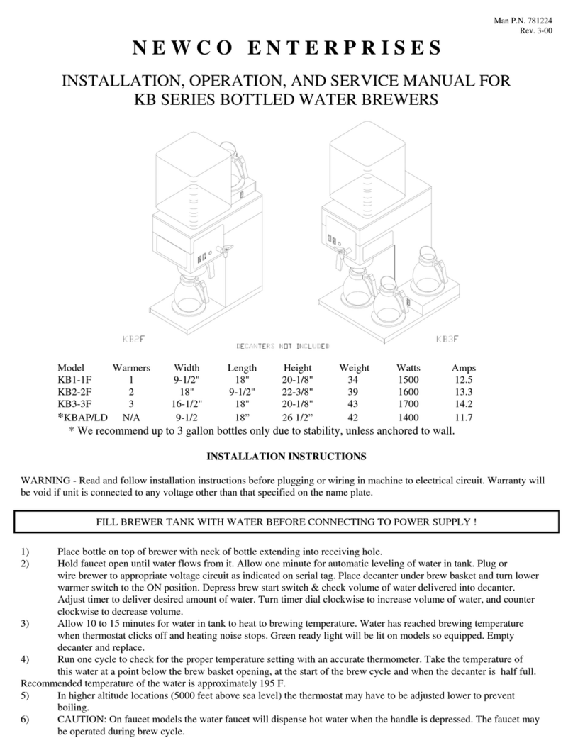
Newco
Newco KB Series Installation, operation and service manual

Keg King
Keg King KEGMASTER XL user manual

