Tool-Temp TT-180 User manual

Manual
BA 1152e
EL 1634 d/e/f/it
07/2007
B-0670
Temperature control unit
TT-180
TOOL-TEMP AG Tel.: +41 (0)71 644 77 77
Industriestrasse 30 Fax: +41 (0)71 644 77 00
Schweiz – Suisse – Switzerland Internet: www.tool-temp.ch

Manual TT-180 - 1 -
Contents page
1. Description..........................................................................................................................................2
2. Technical data.....................................................................................................................................2
3. Safety and use as agreed ...........................................................................................................3 - 4
4. Installation......................................................................................................................................4 - 7
4.1 Fluid connections ...................................................................................................................5
4.2 Power supply..........................................................................................................................5
4.3 Filling......................................................................................................................................6
4.4 Pump rotation check...............................................................................................................7
5. Heat transfer liquid............................................................................................................................7
5.1 Water......................................................................................................................................7
5.2 Heat transfer oil......................................................................................................................7
6. Operations...........................................................................................................................................8
6.1 Setting of the temperature......................................................................................................8
6.2 Change over of the heating power .........................................................................................8
7. Safety devices.....................................................................................................................................9
7.1 Pump......................................................................................................................................9
7.2 Heating...................................................................................................................................9
8. Monitoring devices.....................................................................................................................9 - 10
8.1 Level control...........................................................................................................................9
8.2 Temperature monitoring.......................................................................................................10
8.3 Indication of faults (audible alarm)........................................................................................10
9. Inspection and maintenance (according to DIN 31051)..................................................10 - 11
9.1 Inspection.............................................................................................................................10
9.2 Maintenance.........................................................................................................................11
10. Failure corrective action.........................................................................................................12 - 13
11. Control panel.....................................................................................................................................14
12. Views and dimensions (mm)..................................................................................................15 - 17
12.1 Rear view .............................................................................................................................15
12.2 Front view.............................................................................................................................15
12.3 Connecting dimensions........................................................................................................15
12.4 Inside view............................................................................................................................16
12.5 Inside view switch cabinet....................................................................................................17
13. Temperature controller MP-888.............................................................................................18 - 21
13.1 Programming MP-888: Temperature control units without flow control.........................19 - 21
14. Spare parts and pump spares...............................................................................................22 - 24
14.1 Spare parts....................................................................................................................22 - 23
14.2 Pump spares for pump type E..............................................................................................24
15. Change over water / oil operation ...............................................................................................25
16. Electrics ......................................................................................................................................26 - 28

Manual TT-180 - 2 -
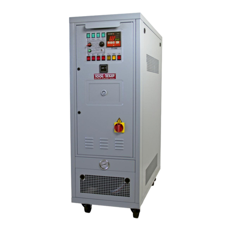
1. Description
The temperature control unit TT-180 is constructed for water operation up to maximum +90°C,
respectively oil operation up to maximum +150°C. For permanent use over +130°C you should use
an other model.
The unit corresponds to the harmonized EU norms as EN 292 / EN 60204 as well as to the relevant
EU directives (see EU conformity declaration) and it is provided with the CE sign.
The TT-180 can be switched from 9 kW for water operation to 3 kW for operation with heat transfer oil.
(see chapter 6.5 and instructions in chapter 15).
serial equipment:
- self-optimizing temperature controller with digital display of the set and actual temperature. Display
in 1/10-° range. Switchable from °C to °F.
- automatic temperature monitoring. Deviation between effective and set temperature activates an alarm.
- switchable from 3 kW oil operation to 9 kW water operation
- heating switchable in stages at 9 kW water operation
- lime-free heat exchanger
- horn for fault messages
- automatic level control to prevent the unit from running dry
- mechanical safety thermostat and electronic temperature limiter installed in the controller
- autom. water refill or manual oil refill
- with main switch, automatic cutout, transformer and motor protection switch
- with castors
2. Technical data
Temperature range Up to +90°C with water / up to +150°C with oil
Temperature control self optimizing microprocessor controller MP-888
heating power water operation: 9 kW, switchable in stages 3/6/9 kW
oil operation: 3 kW
pump capacity connected load 0,75 kW
pressure mode max. 4,5 bar / max. 75 l/min.
suction mode - vacuum max. 8 mWS
cooling power approx. 18 kW at +90°C
filling amount approx. 6 litres
Connections heating medium R 1/2“ female thread
cooling water R 3/8“ male thread
dimensions in mm
(incl. castors)Length: 670
Width: 260
Height: 650
Weight empty ca. 55 kg
category of protection IP-44
Electric In separate switch cabinet, easily accessible from the front
Colour silver grey RAL 7001
heat exchanger low-maintenance
noise level (dBA) < 70 (distance 3 m)

Manual TT-180 - 3 -
3. Safety and use as agreed
The temperature control unit must not be used for other than the described purpose within the fixed
values for temperature and voltage for the temperature control of moulds. Any other use to which we
have not agreed to is strictly forbidden. The use of others than the prescribed heating mediums (water with
9 kW / heat transfer oil with 3 kW - see chapter 5) and/or the use of others than the admitted spare parts
can lead to dangerous operating states and is strictly forbidden. When the unit’s construction state is
changed the operating permission and the conformity declaration become invalid.
Important information in this manual is marked as follows:
remark:
helpful information
CAUTION!
RISKS WHICH CAN LEAD TO MATERIAL DAMAGE
DANGER!
RISKS WHICH CAN LEAD TO PERSONAL INJURY
The TT-180 is equipped with the following pictographs (according to DIN 4844) to mark the remaining
dangers (according to EN 1050) the following:
DANGER! VOLTAGE
DANGER! HOT SURFACE

Manual TT-180 - 4 -
DANGER!
- The temperature control unit must not be used in hazardous location.
- The temperature control unit must not be used in the open air (category of protection IP-44).
- The temperature control unit must not be transported in a horizontal position.
- With 9 kW heating power you are only allowed to use water as heat transfer liquid.
With 3 kW oil operation the admitted heat transfer oils or equivalent products have to be used.
WHEN USING UNSUITABLE HEAT TRANSFER OILS
THE UNIT CAN BE DAMAGED WHICH LEADS TO FIRE RISK
AND THEREFOR TO RISK OF INJURY.
4. Installation
Before starting the unit the external connections of the hydraulics and of the electric have to be mounted.
CAUTION!
WHEN STARTING THE UNIT WITHOUT THE PRESCRIBED
CONNECTIONS THE UNIT CAN BE DAMAGED.
CAUTION!
- THE UNIT HAS TO BE INSTALLED IN A SUITABLE LOCATION
ON EVEN GROUND.
- THE UNIT IS NOT PROTECTED AGAINST SPLASH WATER
AND IS NOT SUITABLE FOR USE IN HAZARDOUS LOCATION.
- THE UNIT MUST NOT BE USED IN THE OPEN AIR.
The starting of the unit has to be done in the order of this chapter.
After the proper starting the unit is ready for use.

Manual TT-180 - 5 -
4.1 Fluid connections
For the hoses of the heating medium circuit and cooling water the following minimum internal diameters
and hose qualities are recommended:
heating medium R 1/2“ female thread
internal hose diameter 13 mm
cooling water R 3/8“ male thread
internal hose diameter 10 mm
water filter at the cooling water inlet R 3/8“ female thread
The use of pressure and temperature resistant hoses is recommended for safety (pressure resistant up to
min. 10 bar). It is important to use hoses which are resistant to heat transfer liquids.
MARK AND TAKE DOWN THE MAXIMUM TEMPERATURE
FOR WHICH THE CONNECTIONS ARE SUITABLE.
Quick release couplings will give reduced flow.
If the recommended tube size cannot be connected to the mould, the connection at the mould should be
reduced and not the connection on the temperature control unit. In this way pressure drops can be avoided.
4.2 Power supply
Mains voltage and frequency according to the serial plate.
Pay attention to the local regulations during the installation of the unit.
CAUTION!
THE CONNECTION TO THE POWER SUPPLY HAS
TO BE DONE BY A COMPETENT ELECTRICIAN.
colours of cables:
phases black / black / black L1 / L2 / L3
earth yellow/green PE
max. power consumption: 10 kW
DANGER!
DO NOT CONNECT THE POWER SUPPLY UNTIL
THE HEATING MEDIUM HOSES ARE CONNECTED.

Manual TT-180 - 6 -
4.3 Filling
filling amount: approx. 6 litres
Automatic filling (only for water operation):
- The unit has to be connected hydraulically and electrically.
- The ball valve (behind the solenoid valve) of the automatic filling has to be open (see chapter 15).
- Switch the unit on.
- After switching on the unit the tank will be filled with water via the cooling connection to the correct level.
- Only when the system has reached the minimum level, the pump will start running.
- We recommend to add an anti-corrosion agent via the filling neck at the rear side of the unit.
CAUTION:
SHOULD THE WATER BE FILLED IN MANUALLY, IT HAS TO
BE CONSIDERED THAT NO WATER WITH CHLORIDE
ADDITIVES SHOUD BE USED. IT IS ALSO FORBIDDEN TO USE
SOLVENTS (FOR EXAMPLE PETROL, TOLUOL, NITRO
THINNER, ETC.)
Manual filling for oil operation:
- The unit has to be connected hydraulically and electrically.
DANGER!
WHEN OPERATING WITH OIL THE BALL VALVE OF THE
AUTOMATIC FILLING HAS TO BE CLOSED (SEE CHAPTER 15).
- Switch the unit on.
- If there is not enough oil in the unit (minimum level not reached) the unit does not start
and the two yellow lamps "level control" are lit.
- Fill oil via the filling neck at the rear side of the unit.
Use a funnel tube to prevent to oil from spilling.
Spilled oil has to be removed immediately and disposed appropriately.
- Fill in the oil till the upper level of the unit is reached and therefore both yellow lamps of the level
control are not lit anymore and the permanent sound of the alarm (in case that it is set to ON)
does not ring anymore. Only when the minimum level in the system is reached, the pump starts.
By pumping away the oil to the consumer the possibility exists that the above lamp
"level control" is lit again (pre-warning) and the horn starts ringing. In this case oil has to be filled in
till the upper level of the system has been reached again.
CAUTION!
- THE FILLING AMOUNT MUST NOT BE EXCEEDED TO
PROVIDE THE BIGGEST POSSIBLE EXPANSION AND
RECIRCULATING VOLUME.
- THE FILLING AMOUNT IS RELATED TO AN AMBIENT
TEMPERATURE OF APPROX. +20°C.
- OVERFLOWN OIL HAS TO BE REMOVED IMMEDIATELY
AND HAS TO BE DISPOSED AS PRESCRIBED BY LAW.
- NEVER LET ANY OIL COME INTO THE SEWAGE SYSTEM
OR SOIL.

Manual TT-180 - 7 -
4.4 Pump rotation check
As soon as the unit has been connected to the mains, hose connections have been mounted and the heat
transfer liquid has been added, the direction of the pump rotation must be checked. The direction of rotation
must be clockwise as shown by the arrow on the ventilation cover.
The direction of rotation can be determined by looking through the ventilation slots.
If the direction of rotation is anti-clockwise invert two phases on the electrical connection.
This has to be done by a competent electrician.
You can also, after the unit has been started, check on the rear side of the unit on the manometer if the
pump is running in the correct direction. If the manometer shows a positive pressure, the pump is running
correctly. If a negative pressure is indicated, two phases on the electrical connection have to be inverted.
This has to be done by a competent electrician.
5. Heat transfer liquid
The unit can be switched from 9 kW heating power for water operation to 3 kW heating power for oil
operation (see chapter 6.5 and change over instructions in chapter 15).
5.1 Water
With 9 kW heating power the unit is for use with water as heat transfer liquid.
The tank can be filled manually or automatically.
CAUTION!
DO NOT USE HEAT TRANSFER OILS OR HEAT TRANSFER
MEDIUM WTF-3 (RESP. POLYGLYCOL) WITH 9 KW HEATING
POWER BECAUSE OF TOO HIGH THERMAL LOAD (CRACKING
OF OIL OR DECOMPOSING OF WTF-3 (RESP. POLYGLYCOL)).
5.2 Heat transfer oil
When using the unit with 3 kW heating power it can be operated with mineral heat transfer oils such as
BP Transcal N, Mobiltherm 605, Shell Thermia Oil B etc. Heat transfer medium WTF-3 resp. polyglycol
can also be used. WTF-3 (resp. polyglykol) affects lacquers and colours, and therefore is not recommended
by TOOL-TEMP AG.
CAUTION!
TOOL-TEMP AG DOES NOT RECOMMEND WTF-3
(RESP. POLYGLYCOL) BECAUSE THIS LIQUID
CORRODES LACQUERS AND COLOURS.
The tank has to be filled manually.
DANGER!
THE USE OF UNSUITABLE OIL SORTS IS NOT PERMITTED
AND IS NOT REGARDED AS USE AS AGREED.
PARTICULALLY DANGEROUS AND THEREFOR PROHIBITED
IS THE USE OF INFLAMMABLE SUBSTANCES.
The used heat transfer oil has to be taken down in a check list. Particularly the maximum operating
temperature according to the specifications of the heat transfer oil manufacturer has to be taken down.

Manual TT-180 - 8 -
6. Operations
For the operating and display elements on the temperature control units see chapter 13 "temperature
controller MP-888 for temperature control units".
6.1 Setting of the temperature
The required temperature on the temperature controller can be adjusted by pressing the flashes
CAUTION!
PAY ATTENTION TO THE MAXIMUM ALLOWED
TEMPERATURES FOR THE USED HEAT TRANSFER
LIQUID AND HOSES.
The lamp in the green switches „heating I – II“ and the red diode in the controller indicate that the operation
mode is HEATING.
Likewise the operating mode COOLING is indicated by the green diode in the temperature controller.
The end user can choose himself if he likes to work with degree Celsius or degree Fahrenheit. When putting
into service the controller the temperature unit will be shown for a short moment.
See instructions „Programming: Temperature controller MP-888“ for details about function and setting
of the controller (see chapter 13).
6.2 Change over of the heating power
Only with a few modifications the unit can be switched over from 9 kW water operation to 3 kW oil operation
and inverse. For the instructions please see chapter 15.
DANGER!
WHEN OPERATING WITH OIL THE BALL VALVE OF THE
AUTOMATIC FILLING HAS TO BE CLOSED (SEE CHAPTER 15).
DANGER!
THE CHANGE FROM WATER TO OIL OPERATION HAS TO BE
DONE VERY CAREFULLY. THE UNIT AND THE PROCESS
MUST BE ABSOLUTELY FREE OF WATER. ONLY A FEW
DROPS OF WATER ARE ENOUGH TO LET THE UNIT EMPTY
BY EXPLOSION AT THE BOILING POINT OF THE WATER.
The change from oil to water operation on the other hand does not need any special measures.
Remaining oil in the water does not cause any problems.

Manual TT-180 - 9 -
7. Safety devices
7.1 Pump
The pump motor is fitted with an overload relay.
7.2 Heating
In the electronic controller the maximum temperature is limited at +150°C.
DANGER:
IT IS NOT ALLOWED TO ADJUST HIGHER TEMPERATURES
THAN 150°C. LOWER TEMPERATURES ARE ALLOWED;
SPECIALLY FOR WATER OPERATION WE RECOMMEND TO
ADJUST THE MAXIMUM VALUES TO 90 – 95°C (DEPENDING
ON THE LOCATION, HIGHT ABOVE SEE LEVEL, THAT HAS
INFLUENCES THE BOILING POINT OF THE WATER).
Exceeding this temperature the heaters switch off.
The temperature of +150°C can be adjusted according to the information sheet „Programming: Temperature
Controller MP-888“.
The mechanical safety thermostat is set to the maximum allowed temperature of approx. +155°C.
Exceeding this temperature the unit stops.
As soon as the temperature falls to approx. +140°C the heaters switch on automatically.
At water operation the maximum temperature on the controller has to be adjusted to +90°C. (Program step
no. 1). The mechanical safety thermostat can be adjusted to +95°C.
8. Monitoring devices
8.1 Level control
The temperature control unit is equipped with two level controls. The yellow lamp above is lit and the
horn (continuous sound) is activated in case that the level is too low.
During water operation the automatic water refill corrects the level. During oil operation oil has to be refilled
on the rear side of the unit.
The unit is still working. The alarm can be set OFF by pressing the horn switch .
If further 2 litres are missing, both lamps are lit. The horn rings with an intermittent sound and the
unit stops. The alarm can be set OFF by pressing the horn switch .
CAUTION WITH OIL OPERATION!
OVERFLOWN OIL HAS TO BE REMOVED IMMEDIATELY
AND HAS TO BE DISPOSED AS PRESCRIBED BY LAW.
NEVER LET ANY OIL COME INTO THE SEWAGE SYSTEM
OR SOIL.

Manual TT-180 - 10 -
8.2 Temperature monitoring
Maximum temperature:
As soon as the maximum temperature has been reached the lamp is lit the horn starts ringing
(intermittent sound) and the unit stops. The alarm can be switched off by the horn switch.
The value of the temperature of the deviation control (factory preset +/- 5°C) can be adjusted on the
controller in program step 02. The starting interlock for temperature deviation control can be switched off in
program step no. 24. See chapter 13 "temperature controller MP-888 temperature control units".
8.3 Indication of faults (audible alarm)
During normal operation the horn should always be switched on.
If the level in the tank drops the horn starts ringing with a continuous sound (pre-warning). The unit
continues to operate. The alarm can be switched off by the horn switch.
If the level falls below the minimum level, the thermal relay of the motor or the mechanical safety thermostat
have been activated, the unit will be stopped and the horn starts ringing with an intermittent sound. The
alarm can be switched off by the horn switch.
9. Inspection and maintenance (according to DIN 31051)
Inspection and maintenance has to be done by trained staff.
Please contact the manufacturer or your supplier for any maintenance or inspection which goes beyond
what is listed.
9.1 Inspection
Before starting the TT-180 has to be checked:
- condition and tightness of the connections for heat transfer liquid and cooling water
- temperature resistance of the hoses
- electrical connections
- with oil operation: suitability of the oil for the choosen operating mode and maximum temperature.

Manual TT-180 - 11 -
9.2 Maintenance
The temperature control unit has to be checked and cleaned periodically.
Before maintenance the unit has to be disconnected from the power supply.
DANGER!
NEVER DO ANY MAINTENANCE WORK ON THE UNIT
BEFORE IT HAS COOLED DOWN. RISK OF BURNING!
The following may be required subject to use and environment:
water filter clean / replace every month
pump motor fan impeller: clean via compressed air every 6 months
hoses and pipes check tightness every 6 months
Bolts and seals check tightness every 12 months
with oil operation:
Heat transfer oil change every 4'000 working hours
Pay attention to the specifications of the oil manufacturer.
These intervals are for standard operation.
For extreme service these intervals must be shortened accordingly.
CAUTION!
WASTE OIL HAS TO BE DISPOSED AS PRESCRIBED BY LAW.
NEVER LET WASTE OIL COME INTO THE SEWAGE SYSTEM
OR SOIL.
Established defects must be repaired.
To guarantee safety the unit must be repaired with original spare parts only.
CAUTION!
DISCONNECT THE UNIT FROM THE POWER SUPPLY
PRIOR TO ANY MANIPULATION ON THE UNIT.

Manual TT-180 - 12 -
10. Failure corrective action
symptom probable cause correction
Green ON/OFF–switch
is not lit, unit is not working - fuse defective
- possibly transformer, relay,
solenoid valve or switch defective
- open the front door
- replace the 5 x 20 mm 1 A fuse
- replace defective parts
Red lamp “motor overload relay ”
is lit.
Horn is activated: - - - - - - - -
The horn can be switched off by the
horn switch .
- Overload relay of the pump motor
has responded.
- the unit switches off (pump)
- possibly 2-phase running
- let the motor cool down
- open the unit’s front door
press the blue button of the
overload relay „motor“
When the motor has cooled down
the unit switches on again.
Red lamp „temperature monitoring“
is lit.
Horn is activated: - - - - - - - -
The horn can be switched off by the
horn switch .
max. unit temperature
reached – thermostat has
responded. The unit switches off
(Pump)
- try to establish the cause – the
thermostat setting may be too low
- check temperature controller
- check contactors
Yellow lamp „level control“
is lit:
Above lamp is lit,
unit is working.
Horn is activated:
The horn can be switched off by the
horn switch
Below lamp is lit, unit is not
working
Horn is activated: - - - - - - - - - -
The horn can be switched off by the
horn switch
preliminary warning
- oil operation:
not enough liquid in the unit
- water operation:
automatic water refill defective or
not connected
actual level below minimum level
- oil operation:
not enough liquid in the unit
- water operation:
autom. water refill defective or not
connected
switch on, check the float
and the electric connections
- oil operation:
refill liquid
- water operation:
open water tap, check solenoid
valve, perhaps clean water filter
- oil operation:
refill liquid
- water operation:
open water tap, check solenoid
valve, perhaps clean water filter
Lamp is lit - There is a fault

Manual TT-180 - 13 -
symptom probable cause Correction
The nominal temperature will not be
reached.
Heating lamp is not lit,
unit is working.
- Temperature delimiter in the
controller switched the heating off.
Perhaps temperature delimiter set
too low.
- Check maximum temperature
setting on the controller
(see „Programming: Temperature
controller MP-888“).
Temperature has stopped rising.
Heating lamp is lit. - solenoid valve of the water cooling
system not closed
- perhaps solenoid valve for water
cooling defective
- maybe too big consumer
- heating defective
- contactor of heating defective
- clean the solenoid valve,
check signal to valve and function
- repair or replace the solenoid
valve
- contact the supplier
- measure resistance of heating
- replace contactor
Unit is working, heating or cooling
system is not working. - temperature controller defective - replace the temperature controller
CAUTION!
DISCONNECT THE UNIT FROM THE POWER SUPPLY
PRIOR TO ANY MANIPULATION ON THE UNIT.

Manual TT-180 - 14 -
11. Control panel
The name plate on the front in the lower left-hand corner shows the following details:
manufacturer and address TOOL-TEMP AG, CH-8583 Sulgen / Switzerland
type TT-180
serial number
Volt
Watt
Hz
sign CE
heating water operation oil operation
I means: step 1 3 kW 3 kW
II means: step 2 6 kW 3 kW
I and II together 9 kW 3 kW see „Programming:
Temperature controller MP-888“
level control lamp:
pre-warning,not enough
liquid in the unit
ON/OFF-switch
unit ON/OFF-switch horn:
ON means that in case
of a defect the horn will
be activated
level control lamp:
dropping below the
minimum level
- Unit switches off
Temperature monitoring –
Temperature deviation control:
max. unit temperature
reached – thermostat has
responded. The unit
switches off (pump)
control lamp:
motor overload relay

Manual TT-180 - 15 -
12. Views and dimensions (mm))
to mould R 1/2“
female thread
from mould R 1/2“
female thread
cooling water out
R 3/8“ male thread
cooling water in
R 3/8“ male thread
mounted water filter
R 3/8“ female thread
fill up point
overflow
drainage point
↻pump rotation in a
clockwise direction
(see from above)
12.2 Front view 12.3 Connecting dimensions
175
150
330
160380
70
260
670
580
650
70
40
12.1. Rear view
manometer
Pressure gauge

Manual TT-180 - 16 -
12.4 Inside view
isolating valve
automatic water refill
pipe to mould
pump with motor
pipe cooling water outlet
by-pass
flat packing for pump
float with rod
float switch
switch cabinet
solenoid valve R 1/4“
(automatic water refill) solenoid valve R 3/8“
(cooling)
terminal box
pipe from mould
pipe cooling water inlet
heating
3 elements each 1 resp. 3 kW heat sensor
controller
tank
tank cover seal heating
Pressure gauge fow
control 40 mm

Manual TT-180 - 17 -
12.5 Inside view switch cabinet
safety thermostat (F10) controller (N1)
horn
(H15)
control fuse
secondary voltage (F8)
main contactor (K1)
control fuse
primary voltage (F7)
contactors for
heaters (K3 / K4)
terminal board for
commutation of
heaters 3kW or 9kW
thermal relay (F1)
pump
transformer for
electric control
(
T1
)
automatic cut-off (F23)
main switch
(Q1)
Indication
lamps
Only 200 – 240 V
50/60 Hz:
Fuse terminals (F27-/2)

Manual TT-188 - 18 -
13. Temperature controller MP-888
cooling switched on
heating switched on
sensor failure
controller is triggered from
external source with a signal of
0-10 V - or 4-20 mA
electronic safety
thermostat
automatic temperature
monitoring / upper and
lower limit contact
programming key:
press the button for
3 sec.
Program steps:
P01 maximum temperature
0-400 °C
(set value +150 °C)
P02 temperature monitoring
limit +/- 20 °C
(set value +/- 5 °C)
see information sheet:
„Temperature controller
MP-888 / programming“
set point
actual value
connections 26 - 28
for external analogue set point
0-10 V oder 4-20 mA
heating
cooling
possible supply voltages –
factory adjusted
current supply
temperature monitoring
(extreme vlaue)
possible heat sensor –
factory adjusted
program version
of the controller
heat sensor connection
set point:
adjustment of the
required temperature
flow control – actual flow value flow control finger tip (reset)
flow control –
minimum flow
flow control
connections 29 + 30
for external analouge actual value
0-10 V

Manual TT-188 - 19 -
13.1 Programming MP-888: Temperature control units without flow control
U = user - parameter, A = agents - parameter, T = TOOL-TEMP – parameter
User code:
Press this touch control for 3 seconds to enter into the program steps
Function Factory adjusted (range) U A T Description
P 1 Maximum temperature 150.0°C / 302.0°F
(0.0...400.0°C)
(32.0...752.0°F)
If the maximum temperature exceeds, the
heating and the cooling will switch off and the
maximum temperature LED lights up.
P 2
Temperature deviation
control
(Deviation between set
and actual temperature)
5.0°C / 9.0°F
(0...20.0°C)
(0...36.0°F)
As soon as the deviation is higher than 5°C
(factory set) the relay and alarm will be
activated.
P 24 starting interlock ON: During heating
up time the temperature deviation control will
only be activated when the set temperature
has been reached for the first time.
P 24 starting interlock OFF: The alarm relay
is activated when the actual value is not in the
range of +/- 5°C – also during heating up
time.
P 3 Flow measurement 0: Manual
1: Automatic
1 automatic: The flow is measured and the
controller presets the alarm value
automatically. At 10 l/min the alarm value is at
30 %, that means 7 litres – at 100 l/min it is
at 10 %, that means 90 litres (adjustable in
program step P 66 + 67). The
green LED lights up as soon as
the flow measurement is
activated.
0 manual: in program step 4 you can adjust
yourself the lower alarm value, independently
from the effective flow.
P 4 Alarm value
Flow 8.0 L
0.1...999.9 L
In case that program step P 3 is adjusted to
manual 0, the lower alarm value can be
adjusted.
P 20 Temperature unit 1: °C
2: °F
Change of temperature unit from degree
Celsius to degree Fahrenheit. When putting
in the controller to operation the adjusted unit
°C or °F will be indicated for a short time.
P 21 Temperature sensor
1: Fe-Ko J
2: NiCr-Ni K
3: Pt 100 2-wire
4: Pt 100 3-wire
Selection of temperature probe/sensor.
Standard temperature control units are
operated with Fe-Ko J.
Newer chillers are used with Pt 100.
See also TOOL-TEMP – controller
adjustment table.
Table of contents
Other Tool-Temp Control Unit manuals