Toolland PM3300 User manual

PM3300
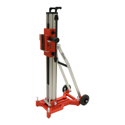
DRILL STAND
SUPPORT POUR PERCEUSE
STANDAARD VOOR BOORMACHINE
SOPORTE PARA TALADRO
STÄNDER FÜR BOHRMASCHINE
SUPORTE PARA BERBEQUIM
USER MANUAL 3
GEBRUIKERSHANDLEIDING 5
NOTICE D’EMPLOI 7
MANUAL DEL USUARIO 9
BEDIENUNGSANLEITUNG 11
MANUAL DO UTILIZADOR 13

PM3300
16/10/2015 © Velleman®nv
2
WPST3
a
Ø5,8 x 21 mm (2x)
b
Ø5,8 x 35 mm
c
Ø5,8 x 50 mm
d
Ø5,8 x 24 mm
e
Ø5,6 x 18,5 mm
WPST4
a
Ø7,64 x 21 mm
b
Ø5,8 x 35 mm
c
Ø5,8 x 50 mm
d
Ø5,8 x 25 mm
e
Ø5,8 x 19 mm

PM3300
16/10/2015 © Velleman®nv
3
User manual
1. Introduction
Thank you for choosing Toolland! Please read the manual thoroughly before bringing this device
into service. If the device was damaged in transit, do not install or use it and contact your
dealer. Damage caused by disregard of certain guidelines in this manual is not covered by the
warranty and the dealer will not accept responsibility for any ensuing defects or problems.
2. Safety Instructions
Keep away from children and unauthorised users.
Always wear a suitable dust mask during use.
Always wear protective gloves during use.
Always wear protective eyeglasses during use.
The drill bit and work piece may become extremely hot. Do not touch with bare hands.
Do not use in an explosive atmosphere.
3. General Guidelines
Refer to the Velleman® Service and Quality Warranty on the last pages of this manual.
Protect this device from shocks and abuse. Avoid brute force when operating the device.
Protect the device against extreme heat, dust and moisture.
Familiarise yourself with the functions of the device before actually using it.
All modifications of the device are forbidden for safety reasons.
Only use the device for its intended purpose. Using the device in an unauthorised way will void the
warranty.
Damage caused by disregard of certain guidelines in this manual is not covered by the warranty
and the dealer will not accept responsibility for any ensuing defects or problems.
Damage to drills, drill bits, work pieces or any personal injury resulting from the use of this device
is not covered by the warranty.
4. Features
base with holes for secure bench mounting
for drills with 38mm or 43mm collar
adjustable drill depth with rule and stop
5. Overview
Refer to the illustrations on page 2 of this manual.
1
base
5
lever
2
column
6
lever support
3
stop
7
preset bolt
4
drill holder
8
ruler
6. Assembly
Insert the column [2] into the base [1] and tighten it securely with the screw(s) [a].
Slide the stop [3] over the column.
Slide the drill holder [4] over the column [2].
Slide the washer and lever [5] over the bolt and use this to secure the drill holder [4] to the
column [2]. Use the included hex key.
Lift the lever [5] and the lever support [6]. Align the holes and insert the bolt [e].
Note: the bolt must be inserted at the side of the lever support [6].
Place a washer over the bolt [e] and tighten the lock nut.
The drill holder [4] has a provision to store the hex key.

PM3300
16/10/2015 © Velleman®nv
4
7. Use
Inspect the drill stand for signs of damage before every use. When damage is noticed, do not
use it. Contact your local dealer for repair and/or spare parts.
Keep the working area clean at all times.
Place the drill stand on a flat and steady surface capable of carrying the weight of the stand and
the work piece. Do not use on slopes etc. …
For security reasons, it is highly recommended to attach the drill stand to the work bench.
Screw 4 screws (not incl.) through the 4 corners of the base [1].
Mark the location of the holes on the work piece.
Place a drill (not incl.) with the desired drill bit (not incl.) in the drill holder [4] and tighten the
bolt [d] and nut. When necessary, use the included plastic reduction ring. Hold the drill holder
[4] with one hand to avoid that it slides down possibly causing damage to the drill bit when it
hits the base [1]. Do not switch on the drill yet.
Pull down the lever [5] and slide down the drill holder until the tip of the drill bit almost touches
the base [1] Slide the stop [3] upwards until it touches the drill holder [4] and secure it tightly
with bolt [b]. This prevents that the drill bit accidentally hits the base during drilling.
Place the work piece on the base [1], align the drill bit with a hole marking and secure the work
piece in such a way that it can not accidentally move during drilling (securing equipment not
included).
Note: Make sure the drill is always above the base [1] when drilling holes.
Lower the drill holder [4] until the tip of the drill bit almost touches the work piece. Tighten the
drill holder [4] securely with bolt [c].
Make sure all bolts are securely tightened before proceeding!
Switch on the drill.
When the drill is at full speed, gently pull down the lever [5]. Depending on the material of the
work piece and the diameter of the drill bit, apply some cooling liquid (not incl.) on the drill bit.
When the desired depth is reached (see ruler [8]), gently lift the lever [5] until the drill bit is
completely out of the hole. Never let go off the lever as this will cause damage to the
mechanism.
Switch off the drill and wait until the drill bit comes to a full stop before handling the work piece.
When multiple holes of the same depth are required, use the preset stop. Release the preset bolt
[7] on the side of the drill holder [4]. Refer to illustration [C].
Drill the hole as described before. When the desired depth is reached, tighten the preset bolt [7].
For the following holes, simply pull down the lever [5] until it will not move any further.
8. Technical specifications
column height
400 mm
column-to-drill centre
105 mm
max. drill depth
60 mm
weight
± 1500 g
Use this device with original accessories only. Velleman nv cannot be held responsible in
the event of damage or injury resulted from (incorrect) use of this device.
For more info concerning this product, please visit our website www.toolland.eu. The
information in this manual is subject to change without prior notice.
© COPYRIGHT NOTICE
This manual is copyrighted. The copyright to this manual is owned by Velleman nv. All
worldwide rights reserved. No part of this manual may be copied, reproduced, translated or reduced
to any electronic medium or otherwise without the prior written consent of the copyright holder.

PM3300
16/10/2015 © Velleman®nv
5
GEBRUIKERSHANDLEIDING
1. Inleiding
Dank u voor uw aankoop! Lees deze handleiding grondig voor u het toestel in gebruik neemt.
Werd het toestel beschadigd tijdens het transport, installeer het dan niet en raadpleeg uw
dealer. De garantie geldt niet voor schade door het negeren van bepaalde richtlijnen in deze
handleiding en uw dealer zal de verantwoordelijkheid afwijzen voor defecten of problemen die
hier rechtstreeks verband mee houden.
2. Veiligheidsinstructies
Houd uit de buurt van kinderen en onbevoegden.
Draag tijdens het gebruik altijd een beschermend masker.
Draag tijdens het gebruik altijd beschermende handschoenen.
Draag tijdens het gebruik altijd een beschermende bril.
De boor en het werkstuk kunnen tijdens het gebruik extreem warm worden. Niet met
blote handen aanraken.
Vermijd gebruik in een explosieve atmosfeer.
3. Algemene richtlijnen
Raadpleeg de Velleman®service- en kwaliteitsgarantie achteraan de handleiding.
Bescherm tegen schokken en vermijd brute kracht tijdens de bediening.
Bescherm tegen extreme temperaturen, stof en vochtigheid.
Leer eerst de functies van het toestel kennen voor u het gaat gebruiken.
Om veiligheidsredenen mag u geen wijzigingen aanbrengen.
Gebruik het toestel enkel waarvoor het gemaakt is. Bij onoordeelkundig gebruik vervalt de
garantie.
Schade door wijzigingen die de gebruiker heeft aangebracht valt niet onder de garantie.
Schade aan de boormachine, de boor, het werkstuk of elke lichamelijke schade valt niet onder de
garantie van Velleman®.
4. Eigenschappen
basis met montagegaten voor bevestiging op werkbank
voor boormachine met boorkop van 38 mm tot 43 mm
instelbare boordiepte met schaalverdeling en dieptestop
5. Omschrijving
Raadpleeg de afbeeldingen op pagina 2 van deze handleiding.
1
basis
5
handvat
2
kolom
6
houder handvat
3
dieptestop
7
afstelbout
4
houder boormachine
8
schaalverdeling
6. Assemblage
Steek de kolom [2] in de basis [1] en bevestig met de schroeven [a].
Schuif de dieptestop [3] over de kolom.
Schuif de houder [4] over de kolom [2].
Plaats de ring en het handvat [5] over de bout en draai vast met de inbussleutel om de houder
[4] aan de kolom [2] te bevestigen.
Hef het handvat [5] en de houder [6]. Lijn de gaten uit en steek de bout [e] in het gat.
Opmerking: Steek de bout langs de kant van de houder [6] in het gat.
Plaats een ring over de bout [e] en draai vast.
U kunt de inbussleutel opbergen in de daartoe bestemde ruimte in de houder [4].
Table of contents
Languages:
Other Toolland Power Tools Accessories manuals
