Toolshop 240-2191 User manual

SAVE THIS MANUAL
You will need this manual for safety instructions, operating procedures and warranty.
Put it and the original sales receipt in a safe dry place for future reference.
For questions about this product, Please call 1-866-915-8626
Operator’s Manual
240-2191
12" DUAL BEVEL SLIDING COMPOUND MITER SAW

2
IMPORTANT SAFETY INSTRUCTIONS
WARNING:When using electric tools, machines or equipment, basic safety
shock, and personal injury.
READ ALL INSTRUCTIONS BEFORE USING THIS TOOL
1. KEEP WORK AREA CLEAN. Cluttered areas can cause injuries.
2. CONSIDER WORK AREA ENVIRONMENT. Don’t use power tools in damp,
wet, or poorly lit locations. Don’t expose tools to the rain. Keep the work area
3. KEEP CHILDREN AND BYSTANDERS AWAY.
away from the work area. Don’t let them handle machines, tools or extension
cords.
4.
5. OBSERVE PROPER PRECAUTIONS REGARDING DOUBLE INSULA-
TION.
6. GUARD AGAINST ELECTRIC SHOCK.
electric shock if you contact a live wire.
7. DO NOT MISUSE THE CORD.
2
immediately.
8. WHEN WORKING OUTDOORS, USE AN OUTDOOR-RATED EXTENSION
CORD.
9. ENSURE THE EXTENSION CORD YOU USE IS OF SUFFICIENT GAUGE
FOR ITS LENGTH.
10. STORE IDLE EQUIPMENT.
reach of children.
11. DON’T FORCE THE TOOL. It
rate for which it was intended.
12. USE THE RIGHT TOOL. Don’t force a small tool or attachment to do the
not intended.
13. DRESS PROPERLY.
Recommended Minimum Wire Gauge for Extension Cords
Amps
from
Tool Nameplate
25’ length 50’ length 75’ length 100’ length 150’ length 200’ length
0-5 amps
5.1-8 amps
8.1-12 amps
12.1-15 amps
15.1-20 amps
!
GROUNDED TOOLS MUST BE PLUGGED INTO AN OUTLET THAT IS
PROPERLY INSTALLED AND GROUNDED.
Bystanders can be a distraction and could be injured.
There should be a low-resistance path to carry

IMPORTANT SAFETY INSTRUCTIONS
SAFETY PRECAUTIONS FOR COMPOUND MITER SAW
14. USE EYE PROTECTION.
or coarse dust.
15. SECURE WORK.
16. DON’T OVERREACH.
17. MAINTAIN TOOLS.
18. AVOID UNINTENTIONAL STARTING. e sure the switch is in the OFF posi
20. DO NOT USE THE TOOL IF IT CANNOT BE SWITCHED ON OR OFF.
21. DISCONNECT THE PLUG FROM THE POWER SOURCE BEFORE MAKING
ANY AD USTMENTS.
if the tool accidentally starts.
22. STAY ALERT.
23. CHECK FOR DAMAGED PARTS.
center. Don’t use the tool if switch does not turn it on and off properly.
24. REPLACEMENT PARTS.
parts.
25. SERVICE AND REPAIRS
shock or injury.
1.
2. WOOD ONLY.
3.
DAMAGED OR WARPED SAW BLADES SHOULD NOT BE USED.
injury.
4.
USE ONLY WITH GUARD IN PLACE.
in use.
5.
REPLACE THE TABLE INSERT WHEN WORN.
part of your saw.
6.
7.
CONNECT YOUR MITER SAW TO A DUST COLLECTING DEVICE IF POSSIBLE.
USE A SAWBLADE SUITED TO THE CUTTING OB AND MATERIAL TO BE
CUT.
19. ALWAYS CHECK AND MAKE SURE TO REMOVE ANY AD USTING KEYS OR
WRENCHES BEFORE TURNING THE TOOL ON.
ALWAYS USE THE BLADE WRENCH TO TIGHTEN THE SAW BLADE ONTO
THE ARBOR.
8.
9. THE MATERIAL SHOULD BE PLACED FIRMLY AGAINST THE FENCE AND
TABLE
ALWAYS USE TABLE EXTENSIONS AND CLAMPS TO SUPPORT THE
MATERIAL WHEN SAWING LONG WORK PIECES.
If this happens, the cutting head could jump out of your hand, or the
workpiece could fly loose, causing serious injury.
.
Use clamps or a vise to hold the work, this will free both
hands to operate the tool.
, k
Watch what you
are doing and use common sense. Do not operate any tool when you are tired,
or using medication which can make you drowsy.
or binding of
;any or mountings, or other conditions
that may affect safe
,

13. Sliding Lock knob
8. Table Extension
14. Blade Spindle Lock knob
SPECIFICATIONS
FUNCTIONAL DESCRIPTION
SAFETY PRECAUTIONS FOR COMPOUND MITER SAW
10. DO NOT START THE SAW WITH THE BLADE IN CONTACT WITH ANY
SURFACE.
cause injury.
11. IF MAKING A CUT USING ONE HAND TO HOLD THE SAW, ENSURE THE FREE
HAND IS CLEAR OF CUTTING AREA.
1
2
3
4
5
6
7
8
910
11
17
1. Trigger Switch
2. Brush Cover
3. Lower Blade Guard
4. Upper Blade Guard
5. Dust Bag
6. Bevel Lock Lever
7. Hold-Down Clamp Assembly
9. Table Extension Lock
10. Miter Lock knob
11. Miter Scale
12. Bevel Scale
13
15. Head Lock Button
15
Contents:Miter Saw,(1)12"x60 Tooth Carbide Blade,(1)Combination Allen Wrench & Phillips Screwdriver,
Laser class: 2 Wave length of Laser: 650nm /DVHURXWSXWP:
(2)Table Extensions,Dust Collection Bag & Product Manual
Voltage: 120 volts AC, 60Hz
Current rating: 15 Amps
Blade Speed: 4000 RPM(No-Load Speed)
Blade Diameter: 12" 60 tooth carbide tipped
Arbor Size: 1"
Positive Miter Stops: 0, 15, 22.5, 31.6 & 45 degree
Miter Angle: 45 degree Left/ 45 degree Right
Bevel cuts up to 45 degree Left & Right
Power Cord: 6 ft
Weight: 36.5 lbs
Cutting Capacity: 90 degree Cross cut 4"x13" 45 degree Miter Cut 4"x8-5/8"
45 degree Bevel Cut 2-3/8"x13" 45 degree Miter/Bevel Cut 2-3/8"x8-5/8"
1
3
4
7
1
11
17
14
potSleveB°0.61
16
12
18
17. Laser Guide
18. Laser Guide On/Off Switch
19
19. Miter Detent Knob
20. Cutting Depth Stop
20
(1)Hold-Down Clamp,
5
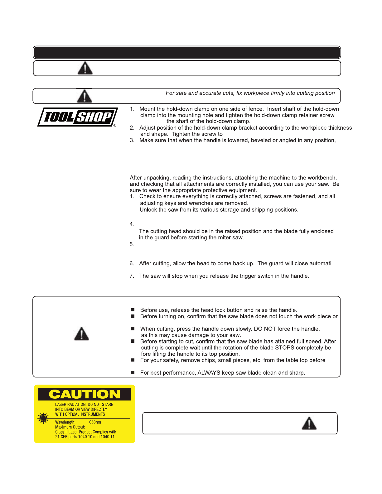
OPERATING PROCEDURES
CLAMPING WORKPIECE:
WARNING: .degamadebyameceipkrowdnalootehtesiwrehto,pmalcnwod-dlohhtiw
no part of the tool contacts the hold-down clamp.
START UP
USING YOUR SAW
CAUTION! Be sure the saw is disconnected from its power source before making
.rewopotwasehttcennoC.3
REMEMBER:
the vise at any position.
-
operation.
-
cally.
Pressing the trigger switch will start the saw.
It can severely damage your eyes.
LASER SWITCH
To turn the switch ON, press the front edge of the switch. To turn the switch
OFF, press the rear edge of the switch (#18 on page 4).
WARNING: Never stare directly at the laser beam.
P:
2.
any repairs or performing any maintenance.
to secure
secure the bracket in place.
To begin cutting, pull the cutting head forward until it is in front of your wood,
then lower the cutting head and push backwards.The lower blade guard
opens automatically.
Table of contents
Other Toolshop Saw manuals


