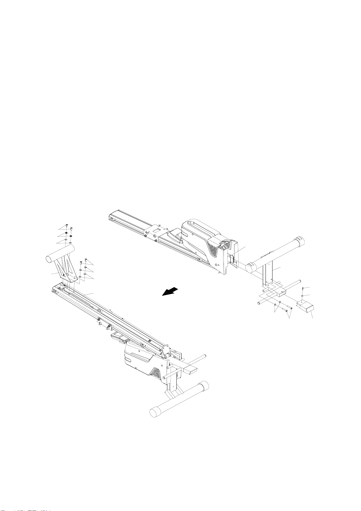
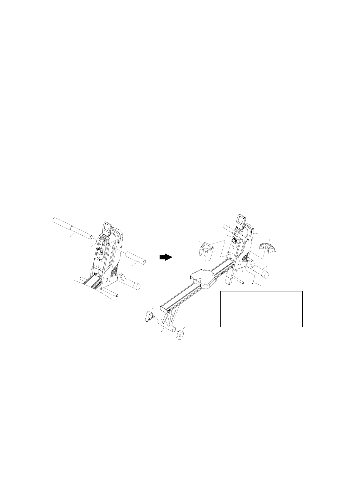
TOORX ROWER ACTIVE PRO User manual

Ed : 09/17 Rev : 00
INSTRUCTION

1
HARDWAREIDENTIFICATIONCHART
This chart is provided to help identify the hardware used in the assembly process. Place the
washers or the ends of the bolts or screws on the circles to check for the correct diameter. Use
the small scale to check the length of the bolt sand screws.
3/16" 1/4" 5/16" 3/8" 1/2"
INCHES
0 1/2 1 1/2 2 1/2 3 1/2 4 1/2 5 1/2 6
0 10 20 30 40 50 60 70 80 90 100 110 120 130 140150
in.
mm.
MILLIMETERS
NOTICE:
The length of all bolt sand screws, except those with flat heads, is measured from below the head
to the end of the bolt or screw. Flat head bolt sand screws are measured from the top of the head
to the end of the bolt or screw.

2
Part No. Description Qty
60
Bolt, Button Head (M8x15mm)
6
61 Lock Washer (M8) 4
62 Washer(M8) 8
63 Cross flat head screws (M6 x 15mm) 5
64 Washer (M6) 5
83
Large Washer(M8)
2
81
Tapping screw (ST4.2X45) 1
84 Bolt, Button Head (M8 x 40mm) 2
85 Bolt, Button Head (M8x20mm) 2
59
Allen Wrench(5mm) 1
69
Allen Wrench w/ Screwdriver 1

3
WHEN YOU OPEN THE CARTON, YOU WILL FIND THE
BELOW SPARE PARTS
1 Main Frame 1pc
3 Base Frame 1pc 21 Seat 1pc 27 Bottle Holder 1pc
28 Front cover 1pc 30 End cap (60mm)
2pcs
Rear Support 1pc 2 Rear Stand 1pc
6 Pedal Shaft 1pc 19 Pedal Cap 2pcs 1 Handlebar 1pc
94 Adapter 1 pc

4
ASSEMBLY INSTRUCTIONS
STEP1
Position the main assembly of the Rowing Machine as shown in illustration A.
Insert the REAR SUPPORT (5) into the BASE FRAME (3) and secure with BUTTON
HEAD BOLTS (M6x15mm) (63) and WASHERS (M6)(64).
Attach the BASE FRAME (3) to the CONNECTION BRACKET (11) with BUTTON HEAD
BOLTS (M8x40mm) (84) and WASHERS (M8) (62).
STEP2
Refer to illustration B. Turn the main assembly of the Rowing Machine upside down.
Attach the REAR STAND (2) to the RAIL (48) with BUTTON HEAD BOLTS (M8x15mm)
(60), LOCK WASHERS (M8)(61), and WASHERS (M8)(62).
48
23
11
62 84
60
61
62
60
61
62
63
64
5
A.
B.

5
STEP3
Refer to the illustration below.
Unfold the RAIL (48), and then attach the CONNECTION BRACKET (11) to the BASE
FRAME (3) with BUTTON HEAD BOLTS (M8x20mm)(85) and WASHERS (M8)(62).
STEP4
Attach the SEAT (21) to the SEAT CARRIAGE (10) with ROUND HEAD BOLTS
(M6x15mm) (63) and WASHERS (M6)(64).
64
63 10
21
64
48
48
85
62

6
STEP 5
Refer to detail view C. Insert the HANDLEBAR (15) through the HANDLEBAR SLEEVE (111).
Slide the FOAM GRIP (22) onto the protruding end of the HANDLEBAR (15). Press the ROUND
PLUG (23) into the end of the HANDLEBAR (15).
NOTE: Lubricate the HANDLEBAR (15) with a small amount of liquid soap or water for easier
installation of the FOAM GRIP (22).
STEP6
Put the END CAP (60mm) (30) into REAR STAND (2).
STEP7
Slide the FRONT COVER (28) onto the LEFT and RIGHT COVERS (17, 18), then attach
to the BASE FRAME (3) with ROUND HEAD SCREW (M4.2x45mm)(81).
STEP 8
To help install the BOTTLE HOLDER (27), loosen the SCREW (M4.2x16mm)(67) on the RIGHT
COVER(18). Push the BOTTLE HOLDER (27) into the gap of the LEFT and RIGHT COVERS (17,
18). Tighten the SCREW (M4.2x20mm)(16) on the RIGHT COVER(18).
15
27
67
17 18 28
81
3
15
103
22
30
30
2
C
( Loosen to install the BOTTLE
HOLDER(27).
Tighten after the installation. )

7
STEP 9
Insert the PEDAL SHAFT (6) through the tube located on the BASE FRAME (3). Slide a PEDAL
CAP (19)onto each end of the PEDAL SHAFT(6). Then secure the PEDAL CAPS (19) with
BUTTON HEADBOLTS (M8x15mm)(60) and LARGE WASHERS(M8)(83) at both ends of the
PEDAL SHAFT (6).You need to use two Allen Wrenches to tighten the BUTTON HEAD BOLTS
(M8x15mm)(60) at both ends of the PEDAL SHAFT (6) at the same time.
STEP 10
Refer to detail view. Plug the ADAPTER (94) into the SOCKET of the DC POWER WIRE (96)
located on the front of the rower. Plug the ADAPTER (94) into an electrical outlet.
83 60
19
83
60
6
19
3
94
96

8
PEDAL STRAP ADJUSTMENT
If you feel it is more comfortable for your workout, you can attach the PEDAL STRAP (20) to the
lower position in the PEDAL CAP(19) as shown in illustration 1 below.
Run the PEDAL STRAP(20) through the opening from the bottom of the PEDAL CAP(19). Pull the
PEDAL STRAP(20) to make the Knot against the bottom of the PEDAL CAP(19).
Run the PEDAL STRAP(20) through the opening in the PEDAL CAP(19) on the other side from
the top as shown in the illustration 1, then make the end of the PEDAL STRAP(20) go up to attach
onto the upper part of the PEDAL STRAP(20) with the Hook & LoopPad.
Attach the end of the PEDAL STRAP(20) to different position with the Hook & Loop Pad to adjust
the length.Refer to illustration 2.

9
STORAGE
1. To store the Rowing Machine, simply keep it in a clean dry place.
2. Move the Rowing Machine with the moving wheels on the Front Stabilizer of the BASE FRAME (3). Lift
the REAR STAND (2) to move the Rowing Machine. Do not use the SEAT (21) to move the Rowing Machine.
The SEAT (21) will move and the SEAT CARRIAGE (10) may pinch your hand or fingers.
3. Refer to the illustration below. You can stand the Rowing Machine on end for storage.
MOVING INSTRUSTIONS
Rise up the rear stabilizer and push the rower machine when you want to move it.

10
COMPUTER INSTRUCTIONS
A. Power up:
a. Connect all of the cables to the monitor.
b. After power up, all LCD segments will light up for 2 seconds and CPU will be reset the
resistance into level 1. The monitor will go to initial mode.
If the connection cables were installed incorrectly, motor will not run. Before asking
service, please examine if all connection cables are well connected and then reset the
power to release the beep sound or press “ START / STOP (Hold to reset) “ button to
restart system. If the motor still don't run, please call service..
B. KEY FUNCTION:
a. START/STOP:
1. To start or pause exercising .
b. FUN/SCAN:
1. Stop condition, press this button to enter parameters Settings
2. Confirm the set values of the parameters and into the next parameter Setting
3. The START state, press this button displays the current fixed parameter values, and
then press the switch for automatic scanning function parameters display
c. ○,
+
▲:
1. In the condition of parameter Settings, increase to adjust parameter values
2. In the START state, increase the resistance movement
d. ○,
-
▼:
1. In the condition of parameter Settings, reduce to adjust parameter values
2. In the START state, reduce the resistance movement.
e. PROG/RESET:
1. STOP state, select the user required movement patterns
2. Any state, long press this button for 5 seconds, electronic watch reset, in addition to
the ODO reset all data
f. A key combination: FUN/SCAN and at the same time the UP (+) button for 3 seconds, into the
introspection of the motor
g. Key combination 2: at the same time, the PROGRAM and the DOWN (-) button for 3 seconds,
examined the ODO values

11
C. FUNCTIONS:
PROGRAM:
Selection of workout mode.
There are total 19 programs P01-P15 ,U1-U4.
TIME:
Exercise time will be shown on the display when exercising. If there is no signal is detected within
256 seconds, enter SLEEP MODE. Work the computer up by pressing any key or signal input or
start work out, all values will reset zero.
Count up: Without setting the time value, the monitor will count up the time from 0:00 to 99:59.
Count down: Setting the exercise time, the monitor will count down from your setting values.
Once reach setting value, monitor will produce BEEP sounds and then stop, press START/STOP
key to count up form 0:00
DISTANCE
The distance will be displayed on the window. The monitor begins to calculate from 1 meter to
999meter and the measure unit is 1 meter. After reach 1 KM, the measure unit become to 0.1
KM (100meter). The monitor will display from 1.000KM to 9.999KM.
Count up: Without setting the distance value, the monitor will count up from 1M-9.999 KM .
Count down: Setting the exercise distance, the monitor will count down from your setting values.
Once reach setting value, monitor will produce beep sounds and then stop, press START/STOP
key to count up form 1 meter
CALORIE
The calories burned will be displayed on the window. Its scope is 0.0-999kcal.
Count up: Without setting the calorie value, the monitor will count up the count from 0.0 to 999.
Count down: Setting the calorie consumption, the monitor will count down from your setting
values. Once reach setting value, monitor will produce beep sounds and then stop, press
START/STOP key to count up form 0.0.
Count:
Count will be shown on the display when exercising. If there is no signal is detected within256
seconds, it will reset zero.
Count up: Without setting the count value, the monitor will count up the count from 0 to 9999.
Count down: Setting the exercise time, the monitor will count down from your setting values.
Once reach setting value, monitor will produce beep sounds and then stop, press START/STOP
key to count up form 0.
WATT
The value of current watt during work out, which will change when the resistance or speed
changes.
STROKES/MIN
It means the movement times of the rower per minute.
D. OPERATION ORDER:
There are total 20 programs and USER can set work out time and then the program divides this
work time into 10 parts ,
If user do not set work time, the program will count up per second, and every parts
count 1 minutes.
Manual program
Preset Program: Program 01- Program 14
1. Press the PROGRAM button to the desired program
2. Press FUN/SCAN button to enter the program.
3. The Time display will flash, and then press the “ up or down” button to set up the desired
time to do the exercise. Press FUN/SCAN button to confirm your setting value
4. The count display will flash, and then press the “ up or down” button to set up the desired
value. Press FUN/SCAN button to confirm your setting value.

12
5. The distance display will flash, and then press the “ up or down” button to set up the
desired distance you would like to reach. Press FUN/SCAN button to confirm your setting
value
6. The calorie display will flash, and then press the “ up or down” button to set up the desired
calorie you would like to reach. Press FUN/SCAN button to confirm your setting value
7. Press the START/STOP button to start work out.
Note:
1. Press FUN/SCAN button to next setting of function.
2. There will be beep sounds when reach the desired value.
If there is more than one desired value, press START/STOP button to continue work out
after beep, and to reach next one.
Competition Program: Program 15
1 Press the PROGRAM button to P15.
2 Press FUN/SCAN button to enter the competition program.
3 The Time display will flash, and then press the “ up or down” button to set up the
desired time to do the exercise. Press FUN/SCAN button to confirm your setting value
4 The distance display will flash, and then press the “ up or down” button to set up the
desired distance you would like to reach. Press FUN/SCAN button to confirm your
setting value
5 Press the START/STOP button to start work out.
Note: 1. Press FUN/SCAN button to the setting of next function.
2. There are two parts of display: the upper and the down part.
The upper: unit work out distance, each bar means 1/10 of desired distance
The down: unit work out time, each bar means 1/10 of desired time
3. When the user reach unit work out time, and the distance is less than unit work out
distance. The distance bars will flash and means user does not reach the desired work
out distance. Otherwise, the bars will increase means the work out is ok.
USER PROGRAM:(U1-U4)
1. Press the PROGRAM button to U1-U4.
2. Press FUN/SCAN button to enter the USER program.
3. The Time display will flash, and then press the “ up or down” button to
set up the desired time to do the exercise. Press FUN/SCAN button to confirm your
setting value
The count display will flash, and then press the “ up or down” button to set up the
desired value. Press FUN/SCAN button to confirm your setting value.
4. The distance display will flash, and then press the “ up or down” button
to set up the desired distance you would like to reach. Press FUN/SCAN button to
confirm your setting value
5. The calorie display will flash, and then press the “ up or down” button to
set up the desired calorie you would like to reach. Press FUN/SCAN button to confirm
your setting value
6. Profile will flash, and then press the “up or down” button to set up the
desired profile value you would like to reach. Press FUN/SCAN button to confirm your
setting value. Setting in same way until finished all profile.
7. Press the START/STOP button to start work out.
Note:
1. There will be beep sounds when reach the desired value..
2. If there is more than one desired value, press any key to continue work out after beep,
and to reach next one.

13
EXPLODED DRAWING
59 69
FRONT
BACK
67
16
67
67
16
16
16
17
18
60
6162
62
62
61 61
60
60
62
61
60
54
54
14
26
91
91
100 99
58 99
8
85
62
66 31
85
66
62
62
61
61
66
65
65
38
38
38
38
62
31
66
85
31
85
31
9
606213
62 60
87 62
5355 75
75
55
53
55
75
62
87
55
75
6266
6266
86
86
437
23
22
22
23
66
62
12
88
76
101
93
1
7
10
45
80
48
27
52
62
62
84
36
82
34
62
85
56
56
3
28
29
29
72
98
68
97
95
96
84
35
24
67
25
15
57
57
33
5
67
67
103
21
64
64
63
63
94
106

14
PARTS LIST
No. PART NAME QTY
1 Main Frame 1
2 Rear Stand 1
3 Base Frame 1
4 Foot Bracket 1
5 Rear Support 1
6 Pedal Shaft 1
7 Rear Spring Hook 1
8 Spring Hook 1
9 Rail Cap 1
10 Seat Carriage 1
11 Connection Bracket 1
12 Magnetic Braket 1
13 Spacer (ø12.8 x 38.5mm) 1
14 Shaft Rod (ø12.8 x 58.5mm) 1
15 Handlebar 1
16 Screw, Round Head Self-Drill (M4.2 x 20mm) 6
17 Left Cover 1
18 Right Cover 1
19 Pedal Cap 2
20 Pedal Strap 2
21 Seat 1
22 Foam Grip 2
23 Round Plug (ø32mm) 2
24 Handlebar Holder 1
25 Strap (13x1.5x1950mm) 1
26 Return Strap (9x2x1700 mm) 1
27 Bottle Holder 1
28 Front Cover 1
29 Wheel Cap 2
30 End cap 2
31 Seat Stopper 4
32 Bearing Housing 2
33 Foot Pad 1
34 Control Motor 1
35 Computer 1
36 Meter Plate 1
37 Foot Stand 1
38 PU Roller 4
39 Return Bearing Housing 2
40 Strap Pulley Shaft 1
41 Strap Pulley 1
42 Bearing (6000RS) 2
43 Bearing (6003zz) 2
44 Pulley 1
45 Bolt, Round Head (M6 x 25mm) 1
46 One-way Bearing (16003) 1
47 Collar 1

15
48 Rail 1
49 Magnetic Flywheel 1
50 Flywheel Shaft 1
51 V-Ribbed Belt (220 PJ3) 1
52 Idler Roller 1
53 Idler Wheel 2
54 Bolt, Button Head (M8 x 20mm) 2
55 Bearing (608zz) 4
56 Round Plug (ø19mm) 2
57 Screw, Round Head (M5 x 20mm) 4
58 Return Spring 1
59 Allen Wrench (5mm) 1
60 Bolt, Button Head (M8 x 15mm) 16
61 Lock Washer (M8) 16
62 Washer (M8) 29
63 Bolt, Round Head (M6 x 15mm) 5
64 Washer (M6) 5
65 Bolt, Flat Button Head (M8 x 32mm) 4
66 Nylock Nut (M8) 9
67 Screw, Round Head (ST4.2 x 16mm) 14
68 Sensor Clip 1
69 Allen Wrench (5mm) w/ Screwdriver 1
70 Bolt, Round Head (M6 x12mm) 6
71 Bearing Housing Cover 2
72 Screw, Round washer Head (M4 x 0.7 x 10mm) 1
73 C Ring (M17) 4
74 Inner C Ring (M35) 1
75 Spacer (ø8 x ø10 x 7mm) 4
76 Retaining Plug 1
77 Eye Bolt (M6) 2
78 Tension Bracket 2
79 Nut (M10) 4
80 Nut (M6) 3
81 Screw, Round Head (ST4.2 x 45mm) 1
82 Screw, Round Head (M5 x 12mm) 4
83 Large Washer (M8) 2
84 Bolt, Button Head (M8 x 40mm) 3
85 Bolt, Button Head (M8 x 20mm) 6
86 Screw, Round Head (M6 x 12mm) 4
87 Bolt, Button Head (M8 x 60mm) 2
88
Bolt, Button Head (M8 x 80mm)
1
89
Spacer (S10)
2
90
Thin Nut (M10 x 1.5, 5mm thick)
3
91
Guide Wheel
2
92
Magnet
2
93
Spring
1
94
Adapter, Output 9V DC, 1A
1
95
Power Wire
1
96
DC
power line
1
97
Female Sensor Wire
1

16
98
Male Sensor Wire
1
99 EVA Pad (180 x 30 x 1mm thick) 2
100 EVA Pad (65 x 15 x 1mm thick) 1
101
Tension Cable
1
102
Bearing (6003RS)
4
103
Handlebar
Sleeve
1
104
Rubber Pad
2
105 Spacer (S17) 1

GARLANDO SPA
Via Regione Piemonte, 32 - Zona Industriale D1
15068 - Pozzolo Formigaro (AL) - Italy
www.toorx.it - info@toorx.it
Table of contents
Other TOORX Home Gym manuals