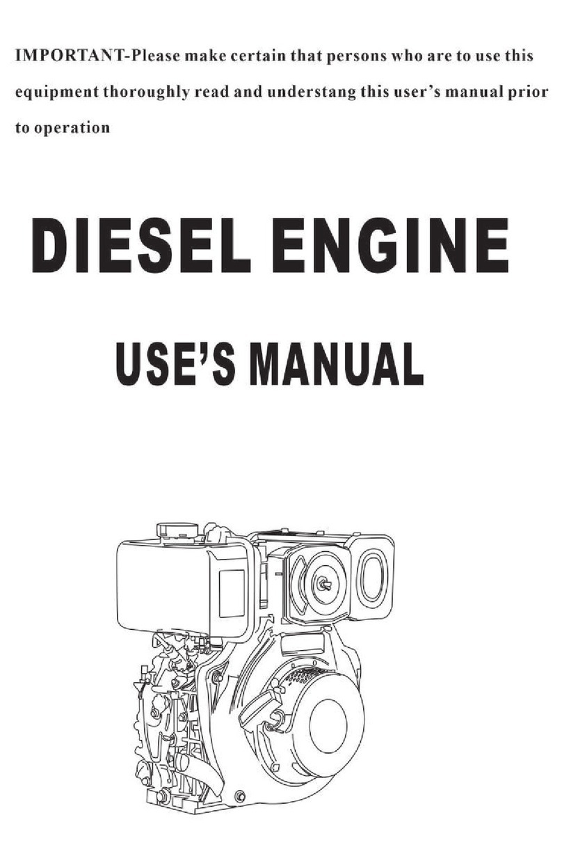
Toowoomba Foundry Southern Cross EF-D User manual

WffiWffiffiffi
MANLIFACTU*?" * AUSTRALa
TOOWOOMBA FOIINDRY PTY. tTD.
AND MARKETED BY
SOUTHERN CROSS MACHINBRY COMPAMES
3+ DIF$[[ Tl\IOIN E
ll/lARK EF-II

4z
this lnrtnrction Manual
* Read through )piraring
'l canefully before Installing or O :
your Engine. -
*. Hang this Instruction Manual in thc
," Errgirre Roorn fqr Future Reference'
3*n*ooJ ,
Remember that this Engine.has beea carefully built' and
has been ,rrr, tr,f,'.,-ti""iiiig iests b"rore -it left the
w""#r. "eil idjurt*"nts are correct and should not bQ,
altered.
A new Engine req i'ffi;^b;;;;;-,;ii;.
lirti t"* days than after the Part:
oughly worked in.
It will take a few days for the various working parts to
set into ,,i." rror#ii".;;iili;"'.*'co"r"q"""tly iny En-
li;;;;;l; b".;;;;'irv ""a carefullv treated at first
wiil rtrn more t*t[i[iv-, itta gttgtallv sive more satis-
factorv results over a longer perrod than one whith has
il;;;";;l,oaded at first'
* This Instruction Manual ht'-!":" preparedto.assist in the In'
stallation, O;;Joi, "oa rvr"i"l""t""e 'of th3 E tet":' :"d
;ffi;;"# ;;i;ir" u"r"re proceedins with the Installation'

SOATHERN CROSS DIESEL ENGINES
Instollcrtion r Opercrtion
and
Mcrintencrnce Imstructions
fur
Wffiffiffiffiffiffiffiffiffiffi
3* H.P. DIHSFL HNGINE
MAR,K EF.D
Page One
14.5/A 1250
r)]tu rr.D&R

L
Page Tu.,o SOUTHERN CRO,SS DIESEL ENGINES
INSTATLATION
The Foundation
The engine should be set up on a firm foundation.
The recommended foundation is a block of concrete as
shown in the illustration, "Genetal Arrangement of 31 h.p.
Diesel Engine, M'ark EF-D", on page 3. The four
foundation bolts supplied with the engine should be set in
the concrete block r'vhen it is made,
The illustration on page 3 also shows the overall
sizes of the engine and the positions of the foundation
bolts. Engine Drive
Engines are supplied for the following types of
dllysg;-
(a) Belt driving from drive end ,of Crankshaft (either
flat or V-Belt Pulley).
(b) Belt driving from extension shaft at flyw,heel end
(V-Belt Pulley).
(c) Direct coupling to driven machine by means of a
fiexible coupling.
(d) Beit driving from 2 : 1 reduction box mounted on
engine (either flat or V-Belt Pulley). Pulley runs
in reverse direction of rotation to engine crankshaft.
(e) Direct coupling by means,of a flexible coupling from
2 : 1 reduction box mounted on engine.
Flexible coupling runs in reverse d'irection of rota-
tion to engine cranhshaft.
INCORRECT
Belt Dtiues
Where a belt drive is being used, the engine will
give you the best ser-vice if you arrange the drive .as
follows:-
The engine should be placed so it will drive with
the tight side of the belt on the bottom side and the
slack side on top ,of ihe pulleys. See illustration, "Belt
Drives", belolv.
The reason for this is to allow the slack side of the
belt to rvrap around the pulleys due to the sag of the
beit, and obtain a more efficient drive by greater belt
contact.
\,VITH FLAT BELT DRIVES ON TO FAST AND
LOOSE PULLEYS, THE BELT, WHEN DRIVING,
SHOULD BE NEAREST THE ENGINE.
Also by use of fast and loose puileys, or a clutch, or
a water by-pass in the case of pumps, or similar arrange-
ment, arrange for the engine to be started free of load.
This will assist starting and enable the engine to attain
its correct rvorking speed quickly.
To Make a Concrete Base
The following instructions are for a concrete base
which is suitable for any of the five types of drives
set out in section "Engine Drive", opposite.
1. Construct a suitable wooden mould. The recommended
sizes for the concrete base are shown .on Page 3.
Nail tu'o pieces of timber across Lhe top of the mould
and then mark on them the positions for the
foundation bolts. The engine sits cenlrally on
the block. Check the distance between the centres
of the bolts diagonally from corner to corn€r. If
the maiking out is correct, the centres should be
12 13/64 inches apart (i.e., 12 3/16in. plus 1/64in.).
Drill I inch holes at the positions marked. Put the
large washers on the foundation bolls and hang them
from these drilled holes. The nuts have to be screwed
on so the tops of the bolts will be 2E inches above
the top of the concrete block. It probably will be
necessary to fit small rvo'oden blocks under the nuts
to act as dislance pieces.
Nail two pieces of timber along the ends of lhe mould
to support it over the foundation hole.
After deciding on the position for the engine, sink
a hole 12 inches to 18 inches deep in the ground
and about 6 inches larger all round than the mould.
The depth of the hole depends on the type of soil-
light soil requiring a deeper hole than hard, well-
packed soil. Holever, always make the block larger
for preference.
Set the mould in position over the hole and check
its position in relation to the machinery it is to drive.
Make sure that the engine will be level by trying a
spirit level across the top of the mould both ways.
If the mould is not level on the top, pack under the
edge until it is.
Arrange some steel bars in the bottom of the hole to
act as reinforcement.
Mix up a batch of concrete, using 4 parts of stone or
rubble, 2 parts of sand, and one part of cement, Fili
the hole to ground level, and then stand a few more
bars in the concrete so they project into the mould.
These will act as reinforcement for the section of
the block above ground level.
DRIVEN MACHINE
CORRECT
2.
4.
5.
6.
7.
8.

\J SOATHERN CROSS DIESEL ENGINES Page Three
I
I
VEE I
PULLEYS-l
ONLY ON
THIS END
'--78
t.2so"
1 24g"
DIA
t. l""sounee
KEYWAYI
t249"
DIA
REDUCTION -"
Box. 6
2.d-----i
L,
General Arrangement of jls H.P. Dieset Engine, Mark EF-D.
r:d I
rcl
r.t6' I
__L__ ______l
When filling the mould, ram it weII, being careful
not to disturb it, and making sure that the mixture
is weII packed under the timber crosspieces. Fill to
the top of the mould.
When the mould is full, smooth off the top with
a mixture of two parts sand and one part cement.
Allow the concrete to stand for .at least 24 hours
before rem,oving the mould. Then dampen the block
and smooth off the sides with a mixture of two parts
sand and one part cement.
9. Lift the engine on to the block and fit a nut and
spring washer on each foundation bolt, but don't
tighten the nuts too tightly until the concrete has set
properly. If the engine does not sit flat on the block,
put thin flat washers in the space before tightening
the nuts,
IT IS IMPORTANT THAT THE BLOCK BE'
ALLOWED TO SET FOR AT LEAST THREE
DAYS BEFORE STARTING THE ENGINE.
Fitting Extension Shaft
Take the extension shaft supplied and fit it to the
flywheel, after seeing that the mating faces are clean.
Fit spring rl'ashers under the heads of the 3 - 2in. x
3in. - 24 U.N.F. setscrervs and bolt up tightly.
Fit starting handle clutch spacing collar on to exten-
sion shaft and screw on the starting handle ciutch and
check for position in relation to the compression, with the
starting handle. By varying the thickness of washers be-
hind the starting clutch, adjust starting handle p,osition
so compression is met on the pull up.
s9"--L-s9"-J I
jr.o8" '" -!
Belt Drive from Crankshaft Pulley
The pulley is supplied in a separate package from the
engine. Fit the key in position and slide the pulley on.
Tighten the pulley locking screw securely.
Belt Drive from Extension Shaft
at Flywheel End
Fit the key in position in the extension shaft and
slide the Pulley on. Tighten the pulley locking screw
securely. Screw ,on the starting handle clutch and pro-
ceed as in section ttFitting Extension Shaft".
Flexible Coupling Drive from
Crankshaft
Where a flexible coupling drive is being used, it is
most important that the c'oupling be very accurately lined
up as its life depends entirely upon the accuracy of the
alignment. The more accurate the alignment, the longer
the life of the coupling will be; but if it is not in line,
the eoupling rubbers will wear out very quickly, and rnay
also cause damage to the engine or driven machine.
1. While the engine block is being made, a suitable
block for the driven machine should be made.
2, Clean the bore of the driving half of the flexible
coupling, and shaft and keyway.

i-
'*.-
Page Four
5.
Lining up Flexible Coupling
Fit the key in place and slide on the driving half of
the coupling until the face of the coupling half is
about 1/16 inch out from the end of the shaft.
Tighten the locking screws.
NOTE: Two locking scre\\,'s are fitted in each coup-
ling half, one on top of the other.
M,ake sure that the bottom locking screw is
tightened firmly in place before fitting and
tightening the top locking screrv.
Fit the driven half of the coupling to the driven
machine. Lift the machine on to the block.
With wooden wedges, adjust driven machine until it
is approximately level, and at the same time see that
it is in line with the engine.
The two halves of the Coupling are the same dia-
meter. Using a metal straigJit edge across the
coupling halves, check if the diameters coincide on
top, underneath, and on either side. Shift the driven
machine and recheck with the straight edge at these
four points until correct.
Then, using a set'of feeler gauges, check the gap be-
tween the Coupling halves ,at the top, underneath,
and on either side. Shift the driven machine until
the gap is the same .a11 round the coupling, and, at
the .same time, check that the diameters coincide,
using the str,aight edge as in (6) above. The driven
m.achine must be adjusted until the maximum mis-
aiignment on the outside of the coupling is less than
.005 inch and the maximum variation in the gap be-
tween the coupling halves is less t,han .010 inch.
When the aiignment is correct, proceed to grout in
the bolts of the driven machine with a mixture of
tw,o parts of cle,an sand and one of cement. When
the holes are full, work the grouting under the
machine base so that it will sit on a firm, level
foundation. This must be very carefully done to pre-
vent the machine from getting out of alignment.
Next day, remove the wedges, tighten the found,ation
bolts, check the alignment, and, with the same grout-
ing mixture, clean up and surface the block.
Next day, shift the driven half of the coupling ,al,ong
the shaft to leave abofi I/32 inch gap between the
halves, and lock it in this position. Fit the rubbers
and pins to the coupling, fit locking nuts with spring
washers under them, and tighten.
The engine can now be started, but not before, as it
is essential that the block be allowed to set for at least
three days before the engine is started.
8.
SOUTHERN CROSS DIESEL ENGINES
Eitting 2:l Reduction Box-
Mark KF-I
1. Take the Pinion supplied *'ith the Reduction Box and
slide it ,on until it is hard up against the Shoulder on
the Crankshaft. The Pinion Locking Screw must be
nearest th,e end of the Crankstraft, and it is important
to see that the Pinion is not put on the wrong way,
Slide fhe key into place and tighten the locking screw
rvith the spanner supplied.
2, Fit the studs supplied with the reduction box into the
Crankcase. Use two nuts locked together to screw
in the studs.
3. Clean the paint from the spigot ,on the crankcase.
Fit the gearbox gasket on to the studs ,and then put
the box in position, fitting spring washers under the
nuts. The reduction box may be mounted in any of
six different positions by altering it on the studs, but
it is preferabie to keep the drive shaft level with, or
below, the Crankshaft level.
4. Undo the nuts ,around the drive shaft bearing hous-
ing, and remove the housing, drive shaft, and bear-
ings. With these parts removed, the nuts c.an be
fitted to the two studs which p,ass through the back
of the box.
5. lVhen replacing the housing, position it so the filling
plug is at tlne 72 o'clock position, and the oil level
plug is at the 8 o'ci,ock position.
6. Remove the oii level plug and the filling plug and
pour Southern Cross Drive Gear Oil-E.P. S.A.E. 90
-into the box until it runs from the oil level hole.
Replace both plugs,
Drives from Reduction Drive Box
1. Belt Drive.
For a belt drive, make sure the key is in position in
the drive shaf't, then slide on the pulley and tighten
the locking screw.
Fit the starling handle clutch spacing collar on to the
drive shaft, and screw on the starting handle clutch.
Check for position in relation to compression with the
starting ,handle. By varying the thickness of washers
behind the starting handle clutch, adjust the starting
handie position, so compression is met on the puli up.
2. Flexible Co,upling Drive.
For ,a Flexible Coupling Drive, fit the parallel key in
the keyu'ay in the crankshaft and slide ,on the driving
half of the coupling until the f,ace of the coupling half
is about 1/16 inch out from the end of the shaft,
Tighten the locking screws.
The remainder of the installation of the flexible
coupiing and the lining up ,are done in a similar
manner to that described in section "Flexible Coupling
Drive frorn Crankshaft", on P,age 3.
Exhaust System
1. If an exhaust pipe is fitted, always turn the end of
the pipe downv'ards, so that any moisture which may
collect in the pipe will run away from the engine.
2, If. a long exhaust pipe is fitted, over 12 feet, use
11 inch pipe and keep it as free from bends as pos-
sible.
Lubricating System
Unscrew the oil filler plug and fill crankcase to the
bottom thread in the filler hole with Southern Cross
Engine Oil-Series 3-D.S. Service (S.A.E. 20). The
sump capacity is 4i pints.
4.
6.
7.
o
10.
11,

SOL]THERN CROSS DIESEL ENGINES
Fitting Oil Bath Air Cleaner
The Oil gith Ai" Cleaner Assembly is to be fitted to
the engine before starting. To do this, fit the Oil Bath
Air Clianer Adaptor to the studs in the Cylinder Head,
and tighten the nuts. IJnscrew the Wing Nut and remove
the Cover. FiIl Oil B,ath up to the oil leve1 mark with
clean engine oil and refit the element and cover.
Fuel SYstem
FilI the fuel tank with fuel which is clean and free
from water. (See page ? for "Fuel Recommendations"')
If in doubt about cleanliness of fuel, strain it through a
fine gauze strainer before filling into tank'
18 Gallon Fuel Tank (Supplied as
o.
1. an Extra)
Disconnect the fuel tank to filter tube and injector
,overflow tube and remove' taking care not to lose
the washers from either side of the banjos.
Remove fuel tank ,and fuel tank brackets from the
engine.
R,emove banjo and collar from the injector overflow
tube by holding them in boiling water for about
4 minute and then withdr,awing and removing them.
The banjo and collar ,are to be fitted to the end of
the longer injector overflow tube, supplied with the
Preparing the Engine For Running
T5 start the engine for the first time, or after an
overhaul, or any operation during whioh the lubricating
oil has been drained fr"om the sump' or after the fuel
tank has been ailowed to run dry, the following instruc-
tions must be carried out in the order given, other^wise the
engine may not statt, ot, if it does, it may be dam,aged'
Check the following (see Pages 4 and 5) :-
1. Fuel in fuel tank.
2. OiI levei in Engine Sump.
3. Oil in Oil Bath Air Cleaner.
Retarding Iniection Timing
(.Export Engines OnlY)
Diesel fuels obtainable outside Australia vary con-
siderably. To assist in starting the engine the injection
timing may be retarded up to 5o from the factory setting.
Degree rnarkings on the flywheei alongside the "Pump"
mark are provided to assist in this 'adjustment.
At the factory, the injection timing is set so that
the fuel ceases to flow when the "pump" mark on the
flywheel is opposite the mark on the fuel pump mounting
plate. (See illustration, "Checking Fuel Pump Timing",
on Page Twelve. )
To retard the injection timing, adjust the fuel pump
r"ocker adjusting screw. Read Section (5), "Check Fuel
Pump Timing", on Page Twelve. Under no circumstances
is the fuel pump timing to be retarded beyond the 5o
marking. Priming Fuel System
IMPORTANT-If you don't follow these instructions
the engine won't start, as the fuel system must be abso-
lutely full of fuel and free from air.
1. Shift fuel stop cock to "on" position by gripping
the knurled sleeve and sliding it downwards as far
as it will go.
2. Disconnect high pressure tube from pump and then
rernove delivery valve connection ("8" on illustra-
tion) and lift the delivery valve off its seat. Replace
valve and connection as so'on as fuel flows without
air bubbles, and be sure the spring is in position.
If the fuel does not flovr after the valve has been
removed, rotate the engine about one turn'
4.
,Page Fiue
engine. Cut this tube to the correct length, and fit
the double banjo and collar supplied with the tank to
the other end. To do this, slide the collar back about
6 inches along the tube and then immerse about 1
inch ,of the tube in boiiing water for about * minute.
Quickly withdraw the tube, slide the collar to ,about
* inch from the end, and push the tube on to the
banjo.
Using the brackets provided, mount the. 18 gallon
fuel tank on.a convenient wall with the bottom of the
tank at le.ast 12 inches ,above the level of the pump
inlet.
Fit the fibre washer provided on the adaptor fitting
and screw it into the bottom of the tank.
Fit the fibre washer provided to the fuel stop cock
and screw it into the adaptor,
7. Cut the fuel tank to filter tube to length and fit it
to the double banjo on the injector overflow tube, and
the fuel stop cock, using the same procedure as above'
Connect the banj,o fittings to the filter and injector,
fitting fibre washers on either side of each banjo.
8. FilI the fuel tank with distillate fuel, which is clean
and free from water (see Page 7 for fuel recom-
mendations,). Never fill the t'ank without pouring
the fuel through the strainer provided in the top of
the tank.
THE INSTALLATION OF THE ENGINE IS NOW
COMPLETE.
See that the contro] rod stop on the fuel pump con-
trol rod is in the running position as shown at "D"
on iilustration (page 6).
Rotate engine until fuel is pumped from the top of
the fuel pump. Then fit the high pressure pipe and
tighten nut at the fuel pump end. Leave the oiher
end of the pipe undone.
Rotate the engine until the fuei is pumped from the
end of the pipe wrlthout air bubbles. Then tighten
nut.
It is important to see that no air is imprisoned in
the fuel line, as it will prevent the engine 'from
starting.
Crank the engine, and, if the fuel is being injected
pr'operly, a decided vibration can be heard and felt
on the high pressure pipe, but if air is still in the
fuel pipe, the fuel vrill not be injected, and it will
be necessary to further bleed the system.
The engine is now ready to,start.
5.
6.
2.
RUNNING INSTRUCTIONS
o.
4.
5.
6.
LIFT VALVE
WITHOUT UNTIL FUEL FLOWS
AIR BUBBLES.
Priming Fuel Sgstem

I
SOUTHERN CROSS DIESEL ENGINES
Page Sir.
3+ H,P. Diesel Engine, Mark EF-D'
To Start Engine
C,heck that, when cranking, the compression is met on
tfte putLup. If not, adjust t'iie position of the starting
rri"ai"-.ti,,iih bv the me[hod desciibed in the installation
instrrrctions, "Fitting Extension Shaft", 'on page 3'
1. Oil Valve Rockers.
2. Check Engine Nuts. (Read Section 9, Page 8')
3. Set belt, clutch, etc., oo that engine can bc started
up without its load.
4. Set fuel pump control rod so that fuel will not be
8. Pour sufficient lubricating oil into the priming plug
("E" on iilustration) to fill it, then put into cylindei'
head plate. Up to four fillings may be necessary in
cold weather, but never use more than four fillings
of oil, or pour oil in while the engine is running,
otheru'ise it may be damaged.
NOTE: Use only sufficient oil in the priming plug to
gil'e easy starting. After some experience r.r'ith st.art-
ing it may be found that it is only necessary to partll'
fill the priming plug.
Raise the val'r'e lift handle on the cylinder head cover
(at "A" on illustr.ation) to the vertical position. This
q'iil release the compression.
Crank the engine rapidly for about two or three
turns, shift valve lift handle to the horizontal posi-
tion, and continue to crank the engine, giving a little
extra efrort on the c'ompression stroke until the en-
gine fires. The engine should start providing the
speed is maintained.
If the engine does not start norv you have not fol-
Iowed the above instructions calefully, In very cold
weather the above procedure may not be sufficient to
start the engine, and, in this case, hold a petrol
s'oaked rag around the air filter tvhile starting.
NEVER POUR PETROL DIRECTLY INTO THg
ENGINE.
o
10.
11.
injected.
Diesel engines rely on the heat generated-by com-
"ression if ttre aii charge for ignition' The faster
ltte eneine is cranked, the more readily it will start'
Fiu.ilff swinging engine over c'ompression-so that the
knack of maiitaining speed at the point of maximum
compression can be acquired.
See that the fuel cock is t'on". The knurled sleeve
should be pushed down as far as it will go.
Shift the control rod stop to the "STARTING POSI-
iiOit'1, as shown in the illustration below. .When the
e Eine'has been started, and reaches running speed,
th6 contnol rod stop wilt drop back to the "RUNNING
POSITION'"
1. To Stop Engine
Push the fuel pump control rod towards the starting
end of the engine, and lift the control rod stop to
hold the control rod in this position.
As soon as the engine has stopped, release the con-
trol rod stop so the fuel pump control rod will be in
the correcC position for the next starting of the
engine,
Do not shut off fuel cock after stopping as this may
cause air to collect in the pipes and cause an air
lock.
IMPORTANT: Never stop the engine by means of
the valve lift.
Engine Speed
The engine as supplied is set to run at 2,100 R'P'M'
on full load, which equils about 2,180 R.P.M' on no load'
The engine must not be run at a greater speed Lhan this'
To reduce the engine speed, unscrew the governor
screw adjusting nut ("C" on illustr,ation). If this nut is
tightened, the speed will be increased'
Where the engine speed is altered from the factory
setting, a tachometer should be used to check the new
setting.
Rated Output of Engine
2 B.H.P. at I,200 R.P.M'
2.5 B.H.P. at 1,500 R.P.M.
3 B.H.P. at 1,800 R.P.M.
3.5 B.H.P. at 2,700 R.P.M'
This engine is rated in accordance with British
Standard Specification 649/L958, that is, it will develop
its rated oulput oontinuously up to altitudes of 500 feet
above sea level at temperatures not exceeding 85o F. A
de-rating of 3t% must be made for every 1,000 feet over
500 feet above sea level; plus a de-rating of2/o for every
10o F. above 85o F.; plus a de-rating of up to 6Vo fot
humidity in accordance with B.S.S. Table for Humidity'
Do not vary the speed on load above 2'100 R'P.M'
or below 1,200 R.P.M.
,
t.
5.
6.
7.
STARTING
POSITIoN
RUNNING

SOATHERN CROSS DIESEL ENGINES Page Seuen
FUEL AND LUBRICATING OIL
RECOMMENDATIONS
Fuel
All engines are tested in the Factory with Diesel Fuel,
and the waranted horsepower and fuel consumption have
been produced with it.
The performance of the engine will, however, be
even better if a distillate fuel is used. Less frequent
cleaning of the fuel filter will be necessary and the
engine will give cleaner and smoother running. We
recommend, therefore, that distillate fuel, as supplied by
any reputable oil company, be used.
The fuel pump and injector n'ozzle will be damaged
beyond repair if power kerosene is used as fuel. In an
emergency, mixing I pint of lubricating oil per gallon of
power kerosene will provide a tempor"ary substitute for
the correct fuel.
DO NOT ON ANY ACCOUNT USE MOTOR CAR
SUMP OIL AS FUEL.
In order to ensure the satisfactory operation of this
errgine, certain maintenance routine is advisable. The
accompanying notes indicate the approximate intervals
between the ditrerent inspection operations. These will
probably vary according to site conditions, but these notes
may be used as a guide when the engine is first operated
until the user is able to form his own time table.
This section df the manual does not deal with over-
haul and maintenance of a major nature. Reference
should be made to the next section of the manual, "Over-
haul Maintenance", where the routine for work of a
major character is set out.
Summary of Procedure
Every Day-
1. Oil valve rockers.
2. Check oil level in crankcase.
3. Clean outside of engine.
Every 100 Hours-
4, Drain crankcase and refill with fresh oil .(use cor-
rect grade as specified).
5. Check oil level in reduction gearbox (if fitted).
6. Clean ,air breather valve assembly.
Every 200 Hours-
7. Clean Oil Bath Air Cleaner.
Every 400 flqups-
8. Check valve clearance.
9. Check engine nuts.
Every 500 !trours-
10. Drain oil from reduction box and refill with fresh oil.
Every 1000 Hours-
11. Fit new element to Fuel Filter.
Lubricating Oil
The following lubricating oils are recommended for
use in the Diesel Engine, Mark EF-D:-
Southern Cross Engine Oil Series 3-DS Service-S.A.E.
2O-(Obtainable from the nearest Southern Cross Dis-
tributor).
Or-
If Southern Cross Oil is not available, any other Heavy
Duty Detergent Lubricating Oil, S.A.E. 20, which is re-
commended by,a reputable oil company for service c,ondi-
tions cl,assified by the American Petroleum Institute as
Service DS.
The lubricating oils specified have been scientifically
blended to satisfy the requirements o,f the engine. Engine
life and performance will not be improved by the introduc-
tion of ,additional additives to the lubricating oil.
WARRANTY NULL AND VOID-
If oil other than that recommended for Service DS.
is used, the warranty on the Engine is rendered null and
void.NOTE: It is recommended that with a new engine the
first lubricating oil change should be made after 50 hours'
running. After this, the oil changes should be made in
accordance with the routine as set out in the next section,
"Running M.aintenance".
Doaling with each of the above points in more
detail:-
1. Oil V'alve Rockers:
Every day put a small quantity of oil into the two
oilers in the cylinder head covers. Do,not use an
excessive quantity of 'oil. About half a teaspoonful
in each oiler is sufficient. (Refer "F" in illustration,
Page 6.)
2. Check Oil Level in Crankcase:
The oil level should be checked daily before the
engine is started up. Do not rernove the filling plug
while the engine is running. Keep the oil level up
to the bottom thread in the filling plug hole. Lubri-
cating oil recommendations are given above. Never
use lubricating oil of an unknown brand.
Clean Outside of ,Engine:
After every run, or at least once a week, the engine
should be wiped down and closely inspected.
The cooling fins on the cylinder and cylinder head
must always be kept clean. Any oil or dust on these
fins will hinder the cooling and may result in the
engine being damaged due to overheating.
Dnain Crankcase and Refill with Fresh Oil:
Refer above for lubricating oil recommendations.
Good clean oil increases the life of the engine
and to get the best results it is necessary to drain
the crankcase and refill with fresh oil every 100
hours.
RUNNING MAINTENANCE
o.
4.

Page Eight
T,he oil is to be d1a]n9d when th-e engine is hot; i.e.,
after it has been running fo" ui i.uJi'io.r".
To drain the crankcas","ru*ouu- tiiu i"ui., plog and
the oil will florv out. When the oit-.iop. fi,orving,
replace drain plug.
Then refill crankcase with fresh oil up to the bottom
thread in the filiing pl".e i,oi". -'- *r w
5. Check Oil Level in Reduction Gearbox:
Remove both the oil lev^el plug and the filling plug
and pour in Southern Cloi. b"i"J d"iu" Oif_n.p.
S.A.E. 90-until it runs f""- tn"-rif ilJ"f Irotu. tt un
replace both plugs.
6. Clean Air Breather Valve Assembly:
IJnscrew the air breather valve assembly from the
cylinder head cover and immerse iil;;i;" kerosene.
Remove assembly momentarily, ufio*i"g- dirty kero_
sene t_o drain, and then immerse again. nupuui-tf,i,
procedure several times and tf."" ifl"* all kerosene
to drain from the asseinbly ;;;;;i;* it in the
cylinder head cover..
7. Clean Oit Bath .Air Cleaner:
Remove cover and element and lift off oil bath and
gmrytv out dirty oii. Wash elemeni ani lnsioe of oil
bath with clean netrol. o" t uro.urru a;;-"ii". to dry.
Refit oit bath in nositi"" u;;-;;;,irlo*oii'ruu"r *u"t
with clean engine "ii t;f;" "iiiii"g ""i"*"nt and
cover,
NOTE: In dusty conditions, carry out this procedure
every few days.
8. .Check Valve Clearance:
Check the clearance between the valve rocker and
the top of the vatve stems. _ Th;-";l;;." jould have
the following clearances *f."" 1ir"'Liig.#e is cold:
SOUTHERN CROS., DIESEL ENGINES
Inlet, .012in.; Exhaust, ,014in. Crank the engine
very slowly until tbe .o*pr"rrio., -is -feft. Release
the compression ,and trr"r;h;-lfwtriei stowly untlt
the top dead centre *u.L o"-tt u-'fiu*fr""f is opposite
the mark on the^fuei pump mount"i.,g ptutu. Check
the clearance. rl th9 ir.ur'u""" ir'"oi- cror."ct, ad;.ort
by l,oosening the locknut ""A"" if." "iier enA of the
rocker and then adjusting th;-.;r;;;til the ciear_
ance is correct. .Then tig:hten tf* l""f.""t. Recheck
clearance after tightenirr! trre i;;i;:"
9. Check Engine Nuts:
Before starting engine for the first time, or after an
overhaul, check all nuts-on the ""irfa"'"i the engine,
paf ing particular atte"tio" to cyli"a"" fr""a stud nuts
and nuts rouird the FtywhJ E;J;;;;;"s.Housing.
Repeat this procedur" ;ru"-if*'ilr;:; ,hours, run-
ning, and thereafter, each 400 h;;. -'
10. Drain Oil from Reduction Gearbox and R.efill with
Fresh Oil:
Rerno'e the drain prug and atow a' the oil to drain.
R.eplace plug. Remove fotn ttre oiiferluipros and the
filtirrg ptug and po^ur j; S;";h;;;'b"#ruo"iuu c.""
.Oi]-E.P. S.A.E. 90-u"tff itl"", i.o"Jtr.u oil level
hole. Then replace lotL plugr...^
11. Fit N^ew Paper Element to Fuel Filter:
The fuel fiiter has an elemenl wh-ict i. ,rot intended
to_ be cieaned and must Ue discard-e-J-#u, "i,ofoua.
The period at which it *iii-;;;;i,,rj'iru."..u"y to
change the fiiter element *iri"".vl"1#atng to the
type of.fuei _being used,..utitirrg o"" !*"iiirt"ring uu_
fore_filling the fuel tank, and -tf," "iniitio,.,s under
N'hich. the engine is working.
The fitting ,of a new "l"*ufri ,at.approximately every
1000 hours mav he premature ir, ,o*u l,ur"s but it
should prevent any trouble due to the filter not flow_
ing sufficient ruer.' Howlvl;;tf ;; ;';".tu!a to outuin
the maximum iife from "u.t, "iu_uJt;;;;;;" elemenr
should be kept on hand to prevent unne&ssary delay
when a change has to be m^ade.
t\ew elements are obtainable from the nearest
Southern Cross Sales^.Office. Whe-n ;;l";i;e., specify
that the etement is for a-C.A:V.'ili;;il020 Fuet
Filter.
Jo. frla new element to_the filter, proceed as follows:
(a) Tho-roughiy clean the outsidJ if"tlfr"u'?tit"" *itl, u
cloth.
(b) Unscrerv the central cap nut to release filter
. element and sediment borrl. -
(c) Remove the dilty elemenf and throrv it away.
No attempt should be made to ;i";;;h" element.
Remove any stu.dge ,"a irlu.t ;;;;" sediment
. .. bo*l rvirh petr.cl arrd a11orv fo j; "''
(d) See. thrt the top and bottom seah"ng rings are in
. position and in good order.
( e ) Reassemble the filter with the new element and
scre\1' up cap nut iightly. Undue force should
not be used in an attempt to .r;;l;;s.".
(r) proceed to bteed ilr "l; ?;; i"r.l"roJi3u.r"_ ,,
in "priming Fuel System", F;;;;. -"' "
Checking V alue ClearanceCrAgn)

OVERHAUT MAINTENANCE
This section of the manual deals with the major
overhaul of the engine, and the summar-y of procedure
beiow indicates the approximate intervals between the
various overhaul operations. These intervals may vary
according to conditions, and are given .only as a guide
when the engine is first ,operated until the user is able to
form his ou,'n time table.
Summary of Procedure
Every 500 flopys-
1. Remove Injector Nozzle and Ciean.
Every 1,OO0 Hssas-
2, Grind Valves and Decarbonise.
Every 4,000 Hours-
3. Inspect Piston and Cylinder.
4. Inspect Bearings.
5. Check Fuei Pump Timing.
6. Ciean Exhaust System.
7, Check Governor Adjustment.
Dealing with each of lhe above points in detail:-
1. Remove Injector Nozzle and Clean:
First read section 'on "Fuel Injection Equipment" on
page 14.
Remove the injector and fuel pump to injector tube
and refit the tube to the fuel pump so the injector
can be connected outside the engine.
If the injector is difficult to remove, screw nuts
troosely on to the injector studs and then fiil starter
plug with lubricating oil and put into cylinder head
plate. Crank engine and the injector will be freed.
Crank the engine, and it may be found that the fuel
comes out of the injector nozzle in aimost a solid
stream, and does not atomise. The fuel should be
delivered in a finely atomized spray, and there should
be a distinct snap at the commencement and finish
of the discharge.
If atomization is satisfactory it is oniy necessary to
clean the carbon from around the injector nozzle
with a wire brush, after whioh it can be replaced in
the engine. If it is not, proceed 2s fe|l6rvs;-
(a) Arrange to have a clean bench to rvork on, and
have a small tin of clean diesel fuel or kerosene
available. Absolute dust free cleanliness is
essential.
(b) Remove cap nut which holds the injectot nozzle
to the injector body with the spanner provided,
and examine the nozzle,
The small plunger should work freely in the
nozzle, and to test it, lift the plunger in the
body 1/16th inch .and then it should fall back
on its own weight.
(c) If it does not, remove it and clean it and the
body carefully, and then test again. Very fine
particles of grit will prevent this working, and
it is essential to see that the parts are peifectly
clean before testing. When re-assembling, hold
the parts in clean diesel fuel to exclude ali dust
and grit.
(d) If the_ plunger is still tight, inspect it, and it is
probable that, a small bright spot will show at
some point. This is due to the injector nozzle
warying and binding the plunger. Sometimes it
is possible to correct this by larefully freeing
the plunger in the body. Use a liquid polish,
such as "Brass,o", and pr.oceed as foliows:-
(e) Hold the plunger carefully in a vice by the stem
at the top. Then pour the polish into the nozzle
and work it up and down on the plunger, spin-
ning it at the same time.
(f) Then thoroughly wash jn kerosene and apply
test as to I'hether the valve will fall freelv in
Lhe nozzle.
(g) Reassemble the parts, making sure that the face
of the injector nozzle and the injector body
where they join, is perfectly clean. Tighten the
nut s,o that it is reasonably tight.
(h) Connect the injector to the high pressure tube
again and test before putting in engine,
NOTE: Fit the copper washer on the injector
before replacing it in the engine,
After a considerable amount of running the
injector nozzle will finalty becorne so worn that
it will not function properly, as too much fuel
will leak past the valve. The only remedy for
this js to replace the nozzle.
Grind Valves and Dec,arbonise:
To remove cylinder head, grind valves and decar-
bonise, proceed 2g fell6rrs;-
(a) Disconnect the fuel pump to injector tube and
put protecting plugs in the ends of the tube.
Put pr'otecting caps on the injector and fuel
pump,
(b) Unscrew the injector leak-off connection stud
ald remove the injector overflow pipe. Remove
the injector.
(c) Disconnect the exhaust pipe from the cylinder
head and remove the air cleaner and adaptor.
(d) Remove the two screws holding the fuel tank
brackets to the cylinder head plite. Then loosen
the screws at the b,ottom of the brackets enough
to allow the top of the brackets to sit clear of
the cylinder head plate.
(e) Undo the cylinder head cover nut and remove
the cyiinder head cover and gasket.
(f) Undo the valve rocker support nuts and remove
rocker gear.
(g) Undo cylinder head nuts and the cylinder head
and plate can be lifted off.
Freeing Injector N ozzle
2"

Page Ten
(h) Depress valve springs and remove valve collets,
after rvhich the valves can be withdrawn from
the head.
(i) Ciean away all carbon from the cylinder head,
piston, and inside the combustion chamber.
(j) T" Grind Valves: Light grinding can be done by
the use of grinding pasLe, but if the seats in the
head show any pitting the only satisfactory way
to correct this is to have the seats reground by
the use of a high-speed valve resurfacing
m.achine, such as a Vibro-Centric. The seats are
so hard that the average grinding paste does
not make much impression upon the surface, and
the result is that t^he valve is gr'ound and not
the seat. If the seating is reground, see that the
total rvidth of the seat does not cxceed 3/32 inch.
If it does, by the use of 15 degree and 70 de-
gree grinding wheels reduce the width of the
seat so that it is u'ithin the desired dimensions.
The seat must not be less than 1/16 inch.
NOTE: If the inlet valve seat in the head has
to be reground, use care, as an insert is not
fitted.
If, when the valves require attention, the seating
face of the valve is shouldered so that the
shoulder is sitting on top of the valve seat, the
valve should be refaced to present a flat seating
face at 45 degrees.
(k) After regrinding the valves, thoroughly clean the
cylinder head, valves, valve guides, etc., to re-
move all traces of grinding paste, and then re-
place valves, valve springs, washers, and collets.
(I) See that the cylinder head gasket is in good con-
dition and then replace cylinder head and plate,
putting nuts on loosely.
(m) Now tighten the nuts which are diametrically
opposite and not those adjacent, as this is likely
to distort the cylinder head or cylinder. If a
Torque Wrench is being used, set it at 47 ft. Ibs.
(n) Replace valve rockers.
(o) After replacing Lhe valve rockers, and before
the cylinder head cover is put in position, check
the clearance betrveen the rockers and valve
stems as set out on page 8, ,'Check Valve
Clearance".
(p) Replace rest of parts, reversing the order in
which they were removed.
(q) See that the fuel is being injected properly
after the fuel pump to injector tube has been
fitted, by cranking the engine and listening for
tl.re decided vibratlon r,vhich can be heard if the
fuel is being injected correctly.
3. Inspect Piston and Cylinder:
(a) To r,vithdraw the piston, first remove the cylin-
der head cover and cylinder head as described
above.
(b) Shift the fuel stop cock to the ,,off" position
and disconnect the fuel filter to fuel pump tube
at the pump. Also, remove the fuel pump to
injector tube and put protecting plugs in the
ends of the tube and protecting caps on the in-
jector and fuel pur:lp.
(c) Remove the fuel pump tappet cover, and slowly
turn the flyi,vheei in the normal direction of
rotation. The fuel pump end of the fuel pump
rocker u'ill move up, and then dor,vn. When the
fuel pump end of the rocker is at the bottom of
SOATHERN CftOSS DIESEL ENCINES
the stroke, turn the flywheel another half a turn,
and le'ave it in this position, Replace fuel pump
i,appet c'over.
Undo the nuts around the fuel pump mounting
plate and remove it, being careful not to dam-
age the gasket.
Undo the connecting rod setscrews and remove
the big end bearing cap.
Using a sharp knife, clean away all carbon de-
posits from the top of the cylinder. Then re-
move the ridge from the top of the cylinder with
a sharp bearing scraper or a special ridge cutting
tooi, if available. Remove all of the ridge but
do not cut down into ring travel.
\\Iithdrarv the piston and connecting r.od.
Cylinder: The cylinder will probably give good
selvice until it is u'orn .012 inch oversize. It
nal'be used until it is.015 inch oversize if new
pistcn rings are carefully fitted, but it is recom-
mer.ided that it be rebored to suit an .020 inch
ovelsize piston ri'hen ri'orn .012 inch oversize.
The bore of the c]'linder rvhen nerv is 2.?50
inches, and it shouLd be rebored to 2.??0 inches
to suit a .020 inch or-elsize pist,on.
^{f:er a lebole. run the engine very carefully
fol a ferv da1-s until it is properly run in. Do
noi put it on load for at least four hours after
st:.i'tng up.
Care of Piston: The piston and rings may be
cleaned *-ith soft soap and r,vashed with hot
soda and l'ater, that is, if they are not very
dir-t1-.
If thei'e is much carb,on deposit, or if the rings
are stuck, they must be removed and cleaned.
To Lemove the gudgeon pin from the piston and
rod it is necessary to first remove the circlips.
In some instances, it may be necessary to im-
merse the rvhole assembly in boiling water to ex-
pand the piston sufficiently to ,ailorv the gudgeon
pin to be removed.
The pin must fit the piston tightly in this man-
ner', otherrvise it rvould be to,o slack when the
engine is hot, because of the difference in ex-
pansion betu'een the alloy piston and the steel
gudgeon pin.
To Remove Piston R.ings:
The piston is fitted rvith the following rings -
a "Torsional Chlomol" compression ring in the
top groove, a plain "Torsional" compression
lirg in tite second gtcoye, four segnrents of
"Colcls" rir-igs in the thii.d g1.oo\:e, and an oil ring,
con:isirng' of an erpiitCei' anci tl'o segileuts, iu
the ioulth gioo\-e. To rer.r.rove the t\-,-o contpres-
sion lir.ig-.. lr'olk ilel lc,ose and then spr.ing one
lir.tg cper and pusit :at'i.or.r' .trips of thin sheet
tneial be:r'een r'.ng and piston at four different
point:. \-iork rir:3' oi along the strips of metal-
do not foi'ce liirs ol it rvill break. Repeat this
plocedure r-.'ith the othet compression ring.
To remove the "Cords" Segments, push a finger
nail undel one end of the top segment at the
gap. Lift end of segment and it will unwind off
piston. Repeat this procedure rvith the remain-
ing "Colds" segrnents.
\\rhen lemoving the oil ring from the fourth
groore, push a finger nail under ,one segment at
the gap. Lift the end of the segment and it u'ilI
un-,r'ind off the pislon. Repeat this pr,ccedure
tith the other segment. Lift out the expander.
(d)
(e)
(f)
(e)
(h)
(i)
(i)

vSOUTHERN CROSS DIESEL ENGINES
(k) Testing Piston Rings and Fitting New Piston
Rings:
It is recommended that piston rings be replaced
as a full set when sufficient wear in any one of
the rings in the engine warrants its repl.acement.
Clean the top portion 'of the cylinder to remove
all traces of carbon.
Put a piston ring in place in the top of cylinder.
By inserting bottom of piston into cylinder,
move ring down about 1 inch. This will square
the ring in the cylinder.
Examine gap in ring. If it is more than 1/16
inch, renew ring, Repeat this procedure with
each compression ring,. and each "C.ords" ring
segment.
To fit new rings to the worn cylinder, proceed as
foilows:-
Fit one of the compression rings into the cylinder
and then insert bottom of piston and shift ring
down into the unworn portion at the bottom of
the cylinder; i,e., about 1 inch from the bottom.
Check the gap, and, if it is less than .008 inch,
file joint to obtain this gap. Repeat this pr,o-
cedure with the other compression ring. For the
t'Cords" Segments, use the same procedure, but
make the gap .011 inch with the ring in the un-
worn portion at the bottom of the cyiinder,
To hold "Cords" Segments while filing, make a
hacksaw cut in the edge of a piece of timber,
and use this cut to steady segment while it is
being filed.
Check segments of the fourth groove oil ring in
the unworn portion 'of the cylinder to ensure a
gap of at least .014 inch.
Test compression rings in their respective piston
grooves by rolling them around in the grooves
to see that they do not pinch anywhere.
Piston rings must be fitted to the piston in the
correct order, as foliows:-
Fourth Groove:
Place the expander in the fourth ring groove,
making sure the coloured ends butt together, and
d,o not overlap, that is, so that both colours are
visible. Insert one end of a segment into the
ring groove and wind it into the groove.
Repeat this procedure r.vith the other seg-
ment, on t'he other side of the expander.
Position the gaps in the segments so that they
,are on the same side of the piston, but opposite
the join in the exp,ander. Before replacing the
piston in the cylinder, check that both ends of
the expander are visible, and, if they are over-
lapped, rectify by separating the ends with a
small screwdriver or similar tool.
Page Eleuen
Third Groove:
Special care must be taken to see the segments
are fitted correctly. Each segment is "dished" or
"cupped", and, to determine which is the
"cupped" side, place segment on a flat surface
and press a finger on it at one point. If segment
remains flat, the "cupped" side is f'acing down-
wards, but if the free part .of segment rises, the
"cupped" side is facing upwards. (Refer iliustra-
tion, "Cupped Side of Cords Segments".)
The first segment is put ,on with the cupping
upwards, the second with the cupping down-
wards, the third upwards and the fourth down-
wards. (Refer illustration, " Cords' Segments in
Piston Groove", which shows a sectional view.)
To fit ",Cords" Segments to the piston, do not
spring them open and slide them on using metal
strips as for the other rings. Insert one end of
the segment into lhe groove, allowing the re-
mainder of segment to lie naturally. Then simply
"wind" segment into groove. Repeat this pro-
cedure rvith each segment, taking care not to
cross segments, and also see that the cupping is
correct. All gaps in the segments should be in
line with gudgeon pin ends. Place gap in first
segment over the end of pin, Place gap in second
segment over opposite end of pin, and alternate
each succeeding gap in this manner.
Cupped Sides of "Cords" Segments
ii',.-E-,,-T.:iElT!=,,i-i,,iri,,il ij:r;".!,,-:r.ii1-r,'!-,.:. aT.. .TiE .E :iili,'!
Cupped Stde Downwards
!i:
llili
!j!i
+ 11#f-k#ii
i:l:Lq,r!i.:.Fi-:,.flEF-,:r,:rll;it- i;i"1.il!hi:l:-,i.1.;:,i:.r5!::11.{,.:ti;ijii
"Cords" Segments in Piston Grooue Cupped Side Upwards

r
Page Tutelue
Second and Top Grooves:
After the "Cords" segments have been fitted,
examine the trvo compression rings and it will
be noticed that the outer surface is more highly
polished on one ring. The hishly polished one is
the "Torsional Chromol" ring and must be fittcd
in the top groove. Also it lvill be noticed that
one of the corners on the inside of each ring is
chamfered. The rings must be fitted with this
chamfered corner at the top.
Using metal strips, slide the two compression
rings on to the piston.
(l) Checking Piston: A new piston should be fitted
if the wear on the piston skirt exceeds .015 inch,
or if the side clearance on a new piston ring ex-
ceeds .005 inch. The diameter of the piston skirt
when nerv is between 2.743in. and, 2.742in. al
the bottom. When fitting a new piston, test the
rings in the piston grooves to see they do not
pinch.
(m) To R,eplace Piston:
First make sure the gudgeon pin circlips are
carefully fitted, otherwise the gudgeon pin will
rvork along and score the cylinder.
Turn the compression rings so the gaps are on
opposite sides of the piston and not in line, and
coat piston and rings with lubricating oil,
NOTE: Check that the gap in alternate "Cords"
segments are in line with opposite ends of the
gudgeon pin, and that the ends of the expander
in the fourth groove are not overlapped.
Use a piston ring compressor to compress the
rings when replacing the piston in the cylinder,
One side of the connecting rod is marked "Fly-
wheel Side", and should be fitted nearest the
flywheel.
When refitting the big end of the connecting rod,
make sure the plain half of the bearing is in the
cap and grooved half is in the rod. Fit the
dipper in place on the bottom 'of the rod and
make eure the numbers on the cap and rod are
on the same cide.
When the big end setscrews are tightened up,
turn up the edges of the tab washer to prevent
the setscrews coming loose, If a Torque Wrench
is used to tighten the big end setscrews, set it
at 20ft. lbs.
T.o reassemble the rest of the engine, reverse
the order in which the parts were removed.'
NOTE: When refitting the fuel pump mounting
plate, make sure the eap is in position on the fuel
pump rocker adjusting screw.
4. Inspect Bearings:
The main bearings on the crankshaft are tapered
roller bearings. Unless it is considered that these
bearings are badly worn and need close inspection,
it is sufficient to try them by pushing the crank-
shaft back and forth. When the bearings are pro-
perly adjusted it should be just possible to detect
end play.
If the movement is very noticeable, then adjust as
follows'-
Remove the flywheel end bearing housing from the
crankcase and remove .one packing and refit housing.
Check again for end play, making sure that when
finally adjusted the crankshaft can be easily turned
by hand.
SOATHERN CROSS DIESEL ENGINES
Connecting Rod Big End Bearing:
This bearing is bolted together without any shims.
It must not be filed or ad'justed in any way.
After many hours' running the bearing may wear and
need replacing, In this case, fit a new standard bear-
ing or a .002 inch undersize bearing; or, if necessary,
have the crankpin reground to suit a .010 inch under-
size bearing. To check if the crankpin should be re-
ground, check its diameter with a micrometer and if
it is less than 1.6225 inches, have it reground to
1.615 inches diameter and fit a .010 inch undersize
bearing.
IMPORTANT: When fitting the bearing into the con-
necting rod, make sure that the grooved half is fitted
into the rod and the plain half into the cap,
Connecting Rod Small End Bush:
The inside diameter of this bush is machined to spe-
cial limits afrer it is pressed into the connecting rod,
and, if a nerr- bush is required, it is recommended that
a replacement rod be installed rvith a new bush
alreadl' fitted. This may be done by pr,ocuring a new
connecting rod ol a "sen'ice" rod which has previously
been fitted rvith a nerv small end bush. The connect-
ing lod rrith the worn bush may be returned for in-
spection, freight prepaid, to the Southern Cross S,ales
Office flcm rvhich the engine was obtained and, if
thel- find it suitable for repair, they will make an
allorvance fol it.
Where a customer decides that a local engineering
workshop or g'arage has equipment suitable for press-
ing in a nerv small end bush and boring it to precision
limits, a nes' small end bush will be supplied rough
bored on the inside diameter together with a sheet
detailing the finish boring size.
Timing Camshaft:
If the crankshaft is removed for any reason, make
sure the valve timing is correct when it is replaced.
The marked tooth on the camshaft gear should mesh
between the marked teeth on the crankshaft pinion,
See iilustration, "Timing Camshaft".
PUNCH MARK
Ttming Camshaft

i'vA'LvEr ANo'spRrNG REMovfD
,---._ -..-.. --.-.-ffi
lif; Ffifi t: f Gl.iP-,,U $'lF
vSOUTHERN CROSS DIESEL ENGINES
Checking Fuel Pump Ttming
Check Fuel Pump Timing:
Read this before altering pump tappet setscrew other-
wise pump will be damaged,
It is not necessary to alter this setting under
ordinary circumstances, but it is advisable to check
the pump timing whenever a major overhaul is in
pr,ogress, so that any wear may be adjusted.
Proceed ss fell6ri/s;-
(a) Crank the engine until the compression stroke
is felt, then release the compression wilh the
valve lifter and turn the flywheel until the
"pump" mark is nearly opposite the mark on
the fuel pump mounting plate. Make sure the
control rod stop is released so that the fuel pump
control rod is in the running position.
(b) Remove the fuel pump to injector tube. Then
remove the delivery valve, delivery valve spring,
and delivery valve connection from the pump.
The Delivery Valve Connection should then be
screwed back in and tightened, Fuel will now
flow freely fr,om the pump,
(c) Now turn the flywheel in the normal direction
of rotation until the fuel stops flowing. It will
be necessary to turn the flywheel very sl,owly to
find this point and recheck the position several
times by turning the flywheel backwards and
then slowly forwards to the point where the cut-
off takes place. The mark on the fl:,'wheel
m,arked "pump" should be opposite the mark on
the fuel pump mounting plate'when the fuel
stops flowing.
Page Thirteen
(d) If it is necessary to adjust the pump timing to
take up wear, then remove the fuel pump tappet
cover, No. 62.
(e) With the pump mark on the flywheei opposite
the mark on the fuel pump mounting plate, if
the injection is retarded, undo the locknut on the
fuel pump rocker ,adjusting screw and screw out
very slowiy until the fuel just ceases to flow. If
timing is advanced, screw in very slowly until
fuel ceases to flow.
(f ) Retighten locknut and rec,heck timing as before.
(g) After the setting is correct, wash the delivery
valve and spring in clean diesel fuel or kerosene
and replace, Then connect the fuel pump to in-
jector tube to the fuel pump and pump aII air
from the tube before connecting the other end
to the injector.
Do not put a gasket between the fuel pump and
the machined face on which it sits.
Do not attempt to take the pump to pieces. If
it requires adjustment, return it to the Southern
Cross Sales Office from which the engine was
purchased, or a recognised Fuel Injection Equip-
ment Service Agent.
,Clean Exhaust System:
Periodic cleaning of the exhaust pipe, if fitted, and
silencer is necessary. If the exhaust pipe is clogged
ttre engine will appear overloaded, and will not per-
form well. An engine running on light loads for long
periods may clog up the exhaust pipe or silencei.
To clean the silencer it should be removed from the
exhaust pipe .and tapped sharply on the outside with
a hammer. Then shake the loosened deposit from it.
Check Governor Adj,ustment:
The governor lever adjusting screw in the governor
lever is adjusted,at the Factory and does not normally
require further adjustment, but when a major over-
haul is being carried out it is a good idea to check
the adjustment.
To do this, proceed as follov/s:-
(a) Set fuel pump control rod stop in the ,,starting',
position.
(b) Loosen the locknut on the governor lever adjust-
ing screw,
(c) Fxamine the fuel pump control rod stop and, if
it is not already touching the fuel pump, screw
out the governor lever adjusting screw until it
does touch,
(d) Then very slowly screw the adjusting screw in
until the control rod stop is just starting to move
away from the fuel pump. Leave the adjusting
screw in this position and tighten locking nut.
WARNING: Do not alter the setting of the governor
lever adjusting screw to,alter the engine speed as the
governing of the engine will be affected.
6.
5.
7.
3aq)

r
Page Fourteen SOUTHERN CROSS DIESEL ENGINES
FUEL INJECTION EQUIPMENI,
Extreme care must be taken when handling any of
bhe injection pump and nozzle parts.
They are very accurately made, and if any dirt or
foreign matter gets amongst the working parts, they
will quickly give trouble.
No attempt should be made by the operator to make
any adjustments to the fuel injecLion equipment beyond
those set out in this instruction ma,nual.
If at any time the pump or injeetor does require any
further adjustment, it should be returned to the nearest
Southern Cross Sales Office or a recognised Fuel Injec-
tion Equipment Service Agent.
Fuel Pump
The fuel pump forces the fuel under very high pres-
sure to the injector, which discharges the fuel in a spray
through a fine hole into the combustion chamber.
The fuel pump does not require any adjustment
other than an occasional drop of oil om the control rod,
Injector
The injector is set correctly, and should not be in-
terfered with in any way, beyond ocoasionally cle,aning
the nozzle, if necessary.
When making any adjustments to a nozzle, always
have a tin of clean diesel fuel handy to wash the parts
in. Iniector Setting
The correct injection pressure is 125 atmospheres.
If the injection pressure is tested at any time, and
it is found that the pressure has risen above the correct
setting, the rise is probably due to a partially or wholly
stuck plunger in the nozzle. The nozzle should be freed
as set 'out in the section, "Remove Injector Nozzle and
Clean", on page 9, and the injection pressure retested,
If the pressure is still incorrect, the setting may be
altered, but it is important that no alteration be made to
the setting until a check has been made to see that the
plunger is free in the nozzle.
d%ffi
#ffi
Setting Iniector in an Emergencg
If at an1' time the setting of the adjusting screw at
the back of the nozzle holder is altered by mistake, or if
a ne\\' nozzle is fitted, the nozzle holder with nozzle
should be -:en: to the nearest Southern Cr.oss Saies Office
or lecogn-sed Fuel Injection Equipment Service Agent to
har-e the in.:ec:ol reset to 125 atmospheres,
In an ernergency, an approximate setting can be
made b1' adjusting the screw on the back of the nozzle
to the Cimen-.ror shorvn in the illustration.
Hor,-ever an exact setti,ng can only be obtained by
using specral equipn:rent, and an engine fitted rvith an
injectcr rvhich has been set by the approximate method
shorvn above, will not run as rvell or efficiently as one
with an exact setting.
The above approximate setting should therefore only
be used until such time as it is possible to have the in-
jector set by a Service Agent.
Cleanliness of Fuel
Rernember that the life of the fuel pump and injec-
t'or depends upon the quality and cleanliness of the fuel
used.Nerer use fuel of an unknown quality.
Never run an engine without the fuel filter in posi-
tion.\er-el i'eplace the fuel filter with any type other than
bhat oliginally fitted without first seeking the advice of
your Southern Cross Service Agent.
l
Ua%

!v
.SOATHERN CROSS DIESEL ENGINES Page Fifteen
TROUBTES AND THEIR REMEDIES
Compression ignition engines depend entirely on the
heat generated by process of oompressing the afu to a
very high pressure, and it is this heat only which ignites
the fuel when it is injected into the combustion chamber.
When tracing any troubles, the essential points to
remember are:
(1) Is the compressi'on satisfactory?
(2) Is the fuel being injected properly?
(Refer to Nos. I,2,3,6, 8 under "Failure to
Start" below).
To test the oompression, attempt to crank the engine
over the compression stroke, and unless it takes
quite an effort to do this the compression is not satisfac-
tory, and the reason for the loss of compression can be
located from the faults set out under "Failure to Start,"
Nos. 4, 5 and 7.
Failure to Start
1. Fuel Tank Empty.
2. Failure to Inject.
3. Injector stuck or worn.
4. Exhaust Valve sticking.
5. Exhaust or Inlet Valve leaking.
6. Filter clogged.
7. Piston Rings stuck in grooves.
8. Broken High Pressure Fuel Pipe.
The above may be traced as follows:
(1) Fuel Tank Empty: If the fuel tank is run dry the
fuel system will become air locked, and on refilling
the lank it wiII be necessary to prime the fuel sys-
tem in the same manner as in starting for the first
time. (Refer page 5, "Priming FueI System") and
remove all ,air bubbles fr.om the pipes.
(2) Failure to Inject: This may be caused by:-
(a) air in fuel pipe; (b) Ieaking high pressure fuel
pipe; or (c) leaking delivery valve on fuel pump.
(a) Air in the fuel pipe will sometimes allow the
engine to fire several times and then it will stop,
The air acts as a cushion and prevents the fuel
from being pumped through the pipe. R,efer to
page 5-"p1iming Fuel System"-and correct.
If the fuel cock is shut off overnight, it may
cause air to collect in the pipes and produce an
air lock.
(b) A teaking high pressure pipe will prevent
satisfactory injection. The leak should be re-
paired or a new pipe fitted. AIso, before start-
ing the engine again, make sure there is no
blockage in the injector to have caused the break-
age of the pipe.
(c) If the delivery valve on the fuel pump is leaking,
no fuel will be injected. To correct, remove the
delivery valve, clean it. and inspect.
(3) Injector Stuck or 'Worn: To locate a stuck or faulty
injector, first remove the injector and injector slee.r,e,
reverse the injector on its studs, and co,nnect it to the
high pressure fuel tube outside the engine. Now
crank the engine and it may be found that the fuel
is not being sprayed properly or is being sprayed
erratically. If this is the case, the injector requires
attention. This applies providing the fuel is being
pumped to the injector. Refer to page 9 to correct.
(4) Exhaust Valve Sticking: Where an engine is lightly
Ioaded or overloaded, or where the lubricating oil
leaks past the piston rings, the exhaust valve will get
a gummy deposit on the stem and it will stick to the
guide, preventing the valve from seating properly,
with a resulting loss of compression.
This can usually be freed by pouring kerosene around
the stem and giving the end of the rocker over the
valve a few light blows with a hammer, and at the
same time rotating the engine. In an obstinate case,
turn the flywheel until the "pump" mark lines up
with the mark ,on the fuel pump mounting plate, re-
move the rockers and the collets, washer ,and spring,
and work the valve up and down while ,adding kero-
sene. To replace valve springs, etc., turn flyw,heel so
"Top Dead Centre" is opposite m,ark on plate, This
will hold valve in position for reassembly.
(5) Exhaust or Inlet Valve Leaking: Leaking Valves can
be detected by the sound of air leaking from either,
but before removing the head to grind the f,aulty
valve, it is p'ossible sometimes to correct the trouble,
which may only be due to a small particle of carb.on
lodging between the valve and the seat,
To remove this, crank the engine, and, at the same
time lightly strike the end of the rocker over the
faulty valve with a hamrner.
This should blow the obstruction ,away and restore
the compressio,n, but if Lhis fails, it will be necessary
lo remove the head and grind the valves (pages 9
and 10).
(6) Filter ,Clogged: The symptoms of a clogged filter
will be as follor,r's:
The engine will start and fire several times, and then
stop. After a few minutes it can be started anci will
stop again.
This happens because the filter will not pass suf-
ficient fuel to feed the pump. While the engine is
siopped it will fill the pipe line and for the first
few revolutions the pump will get sufficient fuel,
then the fuel will be used, and the filter will not
ggpply fuel quickly enough and the engine will stop.
(Refer to page 8 fo fit new paper element.)
(7) Piston Rings Stuck in Grooves: Loss of c,ompressiom
may be caused by the piston rings sticking in the
grooves of the piston and not sealing the compression
properly.
To check for this, remove the crankcase cover plate,
cra,nk the engine and the leakage past the rings c.an
be heard.
A further check is to remove the cylinder head
(refer to pages 9 and 10) and inspect the cvlinder
walls. If any of the rings are stuck, there will be a
brown mark on the cylinder wall where the blow-by
has occurred.
The remedy is to remove the piston and free the
rings, and if inecessary, replace with new rings. (Re-
fer to page 10-'(Testing' Piston Rings and Fitting
New Piston Rings.',

-3
,€
Page Sizteen
Engine Stops
If the engine stops suddenly it will be due to one of
the following:
(1) Fuel Tank Empty (refer io No. 1, page 15).
(2) Air in FueI Pipe (refer to No.2, page 15).
(3) Stuck Injector (refer to No. 3, page 15).
(4) Clogged Filter (refer f.o No. 6, page 15).
Knocking
With a diesel engine there is always a certain,amount
of compression knock which must not be associated with a
bearing knock. Knocking may be caused by:
(l) Exhaust Valve Sticking in Guide: This will be a very
severe hammering, and may sometimes be heard
when the engine is starting, stopping, or after it has
been running ,on an overload.
What happens is that the piston strikes the exhaust
valve before it has time to close.
To free it, pour some kerosene down the exhaust
valve stem while the engine is running (refer "Ex-
haust Valve Sticking", page 15).
A sticking exhaust valve is caused through dirty
running due to the engine running on an overload,
or the engine being out of adjustment; amd this must
be c,orrected otherwise the effect of the kerosene
wiil only be temporary.
(2) Too Early Injection: If the timing is altered or the
Camshaft is replaced with the timing in advance, the
pump will inject the fuel too soon, and this will
produce a severe knock which will be very sharp
and distinct.
Refer to page 13, "Check Fuel Pump Timing", and
correct-
(3) Stuck Injector: If the engine runs unevenly and oc-
casionally a sharp knock is heard, it is generally
caused by a stuck injector (refer to page 9, No. 1,
to correct).
(4) Carbon on Injector Nozzle: If, after the engine has
v'armed up, a knock which sounds like, but proves
not to be early injection, is heard, it is gener,ally
due to a carbon deposit forming at the point where
fuel is injected from the r;ozzle, This carbon gets
red hot and ignites the fuel as it enters the combus-
tion chamber, and pr,oduces an early combustion. Re-
move injector nozzle and clean carbon off the end
of the mozzle and replace in the engine, This carb,on
SOATHERN CROSS DIESEL ENGINES
is usually the result of using diesel fuel with the
engine on very light loads, and the remedy is to
change to a Blended Distillate (refer to page 7).
(5) Loose Flywheel: Occasionally a loose flywheel will
produce a very severe knock, lvhich can be quickly
stopped by tightening the flywheel nut. The fly-
wheel fits on a taper o,n the end of the crankshaft
and the nut must be tightened very tightly. Ham-
mer the spanner r,ound with a hammer.
(6) Loose Boarings: A knock from a loose bearing will
be exactly the same on a light lo,ad as on full load,
and can be rec'ognised as it is a dull knock, not
sharp and distinct.
The connecting rod big end bearing can be tested
by removing the crankcase cover and testing the con-
necting rod for up and down movement. If any up
and down piay can be felt, the bearing should be
checked for wear (refer to page l2r "Inspect
Be,arings.")
Overload and Dirty Exhaust
White or grey smoke from the extraust is caused by
Iubricating oil getting up past the pistons due to badly
fitting rings or overfilling the crankcase with lubricating
oil. If the engine shows black smoLe from the exhaustr
it is a sure sign that it is overloaded. Do not continue to
nun the engine but correct the cause of the overload.
Overloading may be caused by:
(a) A load greater than the rated output of the engine.
In this oase, reduce the load. An increased load
could be the result of a iault in the driven machine.
(b) A fault in the engine which is limiti,ng its perform-
ance. In this c,ase the engine can be overloaded on
loads less than its rated output.
This may be caused by: (1) Fuel not being injected
properly in the cylinder; (2) Leaking Valves; (3)
Sluck Piston Ri,ngs,,or (4) General Wear. For causes
7, 2 and,3, refer to section, "Failure to Start" on
page 15. H'owever, if the overload of the engine is
caused by poor perform,ance due to general wear, a
major overhaul should be carried out,
The performance of an engine whicb is run on an
overload will become progressively woroe, so do not eon-
tinue to run the engine but oorrect the oauge of the
overload.
q)q)

-\
SOUTHERN CROSS DIESEL ENGINES Page Seuenteen
"@ss
f
"-B
' J -'t- -rrGl I 'i
---------^O.-'y '198
o
_j

!
Page Eighteen SOATHERN CROSS DIESEL ENGINES
o
/Qt
Its
il
)t) +
;;\
,oo\\ \
,r8r\\ \
N
*s
tol' ,9
/a
,/l
//
":/ (
Table of contents
Popular Engine manuals by other brands
Beckhoff
Beckhoff AS2000 Series Operation manuals
Kohler
Kohler KD27V12 Operation and maintenance manual

TEM
TEM 50V AC Series Operation and maintenance manual
Danfoss
Danfoss H1B 160 cc parts manual

ZIEHL-ABEGG
ZIEHL-ABEGG ZAtop SM180.24/B Original operating instructions

Siemens
Siemens SIMOTICS T-1FW6 Configuration manual


