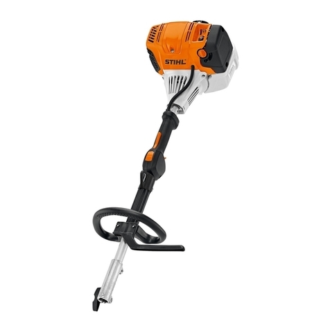
Transmax TR Series User manual


TR Series
Europe Technology & Design
Helical Geared Motor

6
SUMMARIZE
MODEL MARK
RELEVANT PARAMETER
TYPE SELECTION MANUAL
MEANS FOR TYPE SELECTION
SELECTION TABLES COMMENTS
TYPE OF COMBINATION
PERFORMANCE PARAMETER
OUTLINE DIMENSION SHEET
LUBRICANTS
TYPES OF LUBRICANTS
LUBRICANT FILL QUANTITY
INSTALLATION
INSTALLATION POSITIONS DIAGRAM
INSTALLATION POSITIONS
INSTALLATION METHODS
MAINTENANCE
STORAGE
NOTICE FOR ORDER
MALFUNCTIONS
ADDENDUM
CHARGE CHARACTERISTIC CHART
7
Page
8
9 - 12
14
13
15- 16
34 - 105
106 - 185
186
186-187
188
189-193
194
195
196
197
198-199
200-201
CONTENTS
YAD
®
RATIO AND MAX TORQUE
17- 31
SELECTION TABLE
32 - 33
TR2007

7
TR2007 1
SUMMARIZE
TR Series helical gearmotor is a new generation mechanic-electrical integrated product, which
designed basing on the modular system. It can be connected respectively with motors such as normal
motor, brake motor, explosion-proof motor, frequency conversion motor, servo motor, IEC motor and so
on. It can be mounted discretionary six orientation in solid space. This kind of product is widely used in
drive fields such as textile, foodstuff, beverage, chemical industry, automatic arm ladder, automatic
storage equipment, metallurgy, tobacco, environment-protection, logistics and so on.
1. Transmission ratio with fine stage covers a wide range;
2. Compact structure takes up small room;
3. low vibration; low noise; low energy dissipation;
4. Refined design; reliable and wearable; wide usage;
5. Modular, multistructure, can be combined in many forms to meet needs of all kinds of transmission
conditions.
TR Series helical gearmotor
of 1-stage, 2-stage or 3-stage
helical gears
unit and motor. The
helical
gear
which use the material of high quality alloy steel with the surface hardened takes shape through
processing of high-precision equipment. Except the TR..28 housing with aluminum alloy, all are cast iron
housing. housing is exactly processed to ensure the shape and position precision. And it reaches advanta-
geous performance such as: strong bearing capacity, long service-life; small volume; big ratio; light weight,
high efficiency, low noise.
TR Series helical gearmotor
has more than ten models. Combined with TRF series, the multi-stage
gear reduction can be achieved. Power 0.12-160KW; Ratio 1.3-27001;Torque 69-18000Nm. It can
connect (foot, flange) discretionary and use multi-mounting positions according to customers’ require-
ments.
SUMMARIZE
PERFORMANCE CHARACTERISTICS
YUEMA ASIAN DRIVE
®
TR..27
Housing

8
TR2007 3
MODEL MARK
yuema asian drive
®
MODEL MARK
TR F 87 II - YDT 112 M 4 / BMG / HF / TF - 27.88 - M6 / 270
Example:TR47 - YDT71D4 - 121.87
TRXF67 - YDT90S4 / BMG - 1.86 - M1 / R
TRF57III - AM80 - 80.55
1 2 3 4 5 6 7 8 9 10 11 12 13 14
NO
COMMENTS
1TR: code for gear units series
2
I,II,III:B5 output flange specification, default Inot
1). No code means foot-mounted
2). F: B5 flange mounted
3). Z: B14 flange mounted
4). X: single-stage foot-mounted
5). XF: single-stage flange-mounted
to write out is ok
3Specification code of gear units 28, 38,… …
4
51). YDT: motor code
2). AM: IEC input couplings
6Specification code of motor (high in motor centre )
7Length code of stator core D, K, L, M, ML, N, S
82, 4, 6, 8rotomforebmuneloP
91). No code means no brake
2). BMG: brake
10
1). No code means no manual release device
2). HF: manual release device with self-locking function
3). HR:
manual release device with outself-locking function
11 1). No code means no motor heat-protection device
2). TF: motor heat- protection device
12 Transmission ratio of gear units
13 M1: Mounting position,default mounting position M1 not
14 Position diagram for motor terminal box default position
0 (R) not to write out is ok
1) No code means foot-mounted, no flange
2) F: foot-mounted,B5 output flange
3)
to write out is ok

9
YAD
®
TR2007
4
RELEVANT PARAMETER
3) i Transmission ratio i
4) Torque
1) Power
Usually transmission ratio is decimal fraction with 2 radix point tagged in selection tables.
RELEVANT PARAMETER
5) fsService factor fs
The effect of the driven machine on the gear unit is taken into account to a sufficient level of accuracy
using the service factor fs. The service factor is determined according to the daily operating time and
n1
n2
Gear units input speed
Gear units output speed
M2
M2n
P1
η
fs
Output torque
Selected output torque
Input power
Transmission efficiency
Service factor
P1
P2
P1n
fs
η
Input Power
Output Power
Selected Motor Power
Service Factor
Transmission Efficiency
i = n1
n2
M2=9550
•
P1
•
η
n2
The efficiency of TR Series gear units varies with the number or gear stages, between 94 % (3-stage),
96% (2-stage) and 98% (1-stage)
2) Rotation speed
which in selection table means the motor rotation speed 1400/min. If driven by the external gearing,
1400r/min or lower rotation speed is suggested so as to optimize the working conditions and prolong
the service life. Higher input rotation speed is permitted, but in this situation, the rated torque M2
will be reduced.
P1n
≥
P1
• fs[kW]
P1=P2
η
[kW]
M2n
≥
M2
• fs[Nm]
[Nm]
starting frequency Z. Three load classifications are considered depending on the mass acceleration factor.

10
TR2007
Load classifications see the addendum.
5
RELEVANT PARAMETER
YUEMA ASIAN DRIVE
®
Jc
fa
=Jm
To keep the service-life of gear units, the use factor fsselected from the catalogue must be equal or
slightly higher than the calculated use factor fs
1000 1200 1400800600400200
16h 8h
24h
0.8
0.9
1.0
1.1
1.2
1.3
1.4
1.5
1.6
1.0
1.1
1.2
1.3
1.4
1.5
1.6
1.7
1.2
1.3
1.4
1.5
1.6
1.7
1.8
run time (h/day)
start up frequency Z(1/h) #
Service factor ( fs)
#Starting Frequency Z: The cycles include all starting and braking procedures as well as change
over from low to high speed.
Load classifications :
Uniform, permitted mass acceleration factor
≤ 0.2
Moderate shock load, permitted mass acceleration factor ≤3
Heavy shock load, permitted mass acceleration factor ≤10
The mass acceleration factor is calculated as follows:
fa Mass acceleration factor
Jc All external mass moments of inertia ( kgm 2 )
Jm Mass moment of inertia on the motor end ( kgm 2 )
If mass acceleration factors fa>10, please call our Technical Service.
C
B
A
A
B
C
You can read off the service factor applicable to your application in following Figure. The service factor
selected using this diagram must be less than or equal to the service factor as given in the performance
parameter table.

11
YAD
®
TR2007
6
RELEVANT PARAMETER
6)
Radial loads & axial loads Fr2
The overhung loads exerted on the motor or gear shaft is then calculated as follows:
Fr2
Md
d0
fz
Radial loads [N]
Orque [Nm]
Mean diameter of the mounted transmission element [mm]
Transmission element factor
When determining the resulting radial loads, the type of transmission elements, mounted on the shaft
end must be considered. Various transmission elements are corresponding with following
transmission element factors :fz
:
M
d
• 2000 • f
z
Fr2
=
[N]
d
0
The basis for determining the permitted radial loads is the computation of the rated service life LH10
of the bearings (according to ISO 281). For special operating conditions, the permitted radial loads can
be determined with regard to the modified service life Lna. The permitted radial loads Fr for the output
shaft of foot-mounted gear units with a solid shaft are listed in the selection tables.
Contact our company in case of other versions.
The permitted radial loads given in the selection tables must be calculated using the following
formula in the event of force application not in the center of the shaft end. The smaller of the two values
FxL (according to bearing service life) and FxW (according to shaft strength) is the permitted value for
the radial load at point x. Note that the calculations apply to M2 max.
Transmission element Transmission element factor FzComments
Gears 1.00 ≥ 17 teeth
1.15 < 17 teeth
Chain sprockets 1.00 ≥ 20 teeth
1.25 < 20 teeth
1.40 < 13 teeth
V Narrow V-belt pulleys 1.75 Influence of the tensile force
Flat belt pulleys 2.50 Influence of the tensile force
Toothed belt pulleys 2.50 Influence of the tensile force

12
TR2007 7
RELEVANT PARAMETER
YUEMA ASIAN DRIVE
®
= Permitted overhung load (x = L/2) for foot-mounted gear units according to the selection
tables in [N]
= Distance from the shaft shoulder to the force application point in [mm]
=
Gear unit constant for overhung load conversion [mm]
= Gear unit constant for overhung load conversion [mm]
Fr2
x
a, b, f
c
F
xL
= F
r2 •
a
b + x [N]
F
xW
= F
r2 •
c
f + x [N]
x
x
F
r 2
F
r 2
F
X
F
xL
d
d
L
L/2
Gear unit type a
[mm]
b
[ mm]
c
[Nmm]
f
[mm]
d
[mm]
L
[mm]
04022.43501x15.15.325.3457XRT
05527.93501x24.25.725.2567XRT
06030501x59.15.035.0677XRT
08049.84501x96.75.335.3787XRT
001059.35601x34.15.635.6897XRT
021063.26601x74.25.245.201071XRT
05528.11501x65.15.185.60127RT
05520501x42.13981137RT
060351501x44.270173147RT
075381501x77.35.2115.74157RT
07530501x15.25.3315.86167RT
08040501x79.37.3317.37177RT
001050501x74.87.6617.61287RT
021060601x91.15.5915.55297RT
041070601x60.25.5125.582071RT
0710903601x41.65.8525.343371RT
01201133601x56.8792204471RT
0120210701x62.1543054671RT

13
YAD
®
TR2007
8
MEANS FOR TYPE SELECTION
SELECTION EXAMPLE
1) Gear motor
Example:
Required power 16kW on driven machine, work for 8h/day, moderate shock load, so f
s
=1.3,
M6 foot-mounted
, n2=61.9 r/min
Choose type:
TR107 - YDT180L4 - 22.62 - M6
2) Gear units
Example: Recluired torquc 480Nrn on driven machine, work 6h/day, uniform load, so fs=1.2,flange-
mounted, n2=2.5 r/min, choose TR../TRF..
Choose type:
TRF77 / TRF37 - YDT63M4 - 560
M2n
≥
M2
•fs= 480 x 1.2 = 576 [Nm]
P1n
≥
P1
•fs
=
•fs
=
x 1.3
= 21.67 [kW]
P2
η
16
0.96
i = = = 22.62
n1
n2
1400
61.9
i = = = 560
n1
n2
1400
2.5
P1n
≥
P1
• f
s
=
•
f
s
=
x 1.2
= 0.167 [kW]
M2
• n
1
9550
•
η
• i
480x1400
9550 x 0.94 x 0.96 x 560

14
TR2007 9
SELECTION TABLES COMMENTS
YUEMA ASIAN DRIVE
®
L
L1
B
B1
AC
AD
AD1
Total length of gearmotor
Total length of gearmotor including brake
Length of motor
Length of brake motor
Diameter of motor
Center of motor shaft to top part of terminal box
Center of brake motor shaft to top part of terminal box.
SELECTION TABLES COMMENTS
P1n
n2
M2n
M2 max
Fr2
i
fs
page
*
Rated power driving motor [kW]
Output speed [r/min]
Output torque [Nm]
Max. permissible output torque [Nm]
Permissible overhung load output side [N]
Gear unit ratio
Service factor
Gear unit type
Motor type
Dimension sheet page no
Finite gear unit reduction ratio
B1
B
L
L1
AC
AD
AD1

15
TRX/TRXF57
TRX/TRXF67
TRX/TRXF77
TRX/TRXF87
TRX/TRXF97
TRX/TRXF107
TR/TRF17
TR/TRF17
TR/TRF27
TR/TRF27
TR/TRF37
TR/TRF37
TR/TRF47
TR/TRF47
TR/TRF57
TR/TRF57
TR/TRF67
TR/TRF67
TR/TRF77
TR/TRF77
TR/TRF87
TR/TRF87
TR/TRF97
TR/TRF107
TR/TRF107
TR/TRF137
TR/TRF137
Gear Unit Size Stages
The Below is combination Table between gear box and electromotor in each list the ratio range
YDT63/
YDT71 YDT80 YDT90 YDT100 YDT112 YDT132S YDT132M

16
Gear Unit Size Stages
Gear Unit Size Stages
TRX/TRXF77
TRX/TRXF87
TRX/TRXF97
TRX/TRXF107
TR/TRF107
TR/TRF107
TR/TRF107
TR/TRF137
TR/TRF137
TR/TRF147
TR/TRF147
TR/TRF147
TR/TRF147
TR/TRF167
TR/TRF167
TR/TRF167
TR/TRF167
TR/TRF77
TR/TRF87
TR/TRF87
TR/TRF97
TR/TRF97
YDT132ML YDT160M YDT160L YDT180 YDT200 YDT225 YDT250M
YDT280 YDT315 YDT
315M_A/B

17
TRX/TRXF57-67..
TRX/TRXF77-87..
TRX/TRXF87
TRX/TRXF77
AD2
AD2
AD3
AD3
AD4
AD4
AD5
TRX/TRXF57 TRX/TRXF67
AD
AD2
AD3
AD2
AD3
AD
AD AD

18
TRX/TRXF97-107..
TR/TRF17..
TRX/TRXF97
AD
AD3
AD4
AD5
AD6
TRX/TRXF107
AD5
AD4
AD6
AD
3-stages 2-stages
TR/TRF17..

19
TR/TRF27-37..
TR/TRF27 TR/TRF37
AD
AD1
AD1
AD1
AD2
AD2
AD2
AD
3-stages 3-stages
2-stages 2-stages

20
2-stages
2-stages
AD AD
3-stages 3-stages
TR/TRF47-57..
TR/TRF47 TR/TRF57300Nm 450Nm
AD2AD2
AD2
AD3
AD2
AD3

21
2-stages
2-stages
AD AD
3-stages 3-stages
TR/TRF67-77..
TR/TRF67 TR/TRF77600Nm 820Nm
AD2AD2
AD3
AD4
AD3
AD2

22
2-stages
2-stages
AD AD
3-stages 3-stages
TR/TRF87-97..
TR/TRF87 TR/TRF971550Nm 3000Nm
AD2
AD3
AD3
AD3
AD4
AD4
AD6
AD5
AD5
AD4
Table of contents
