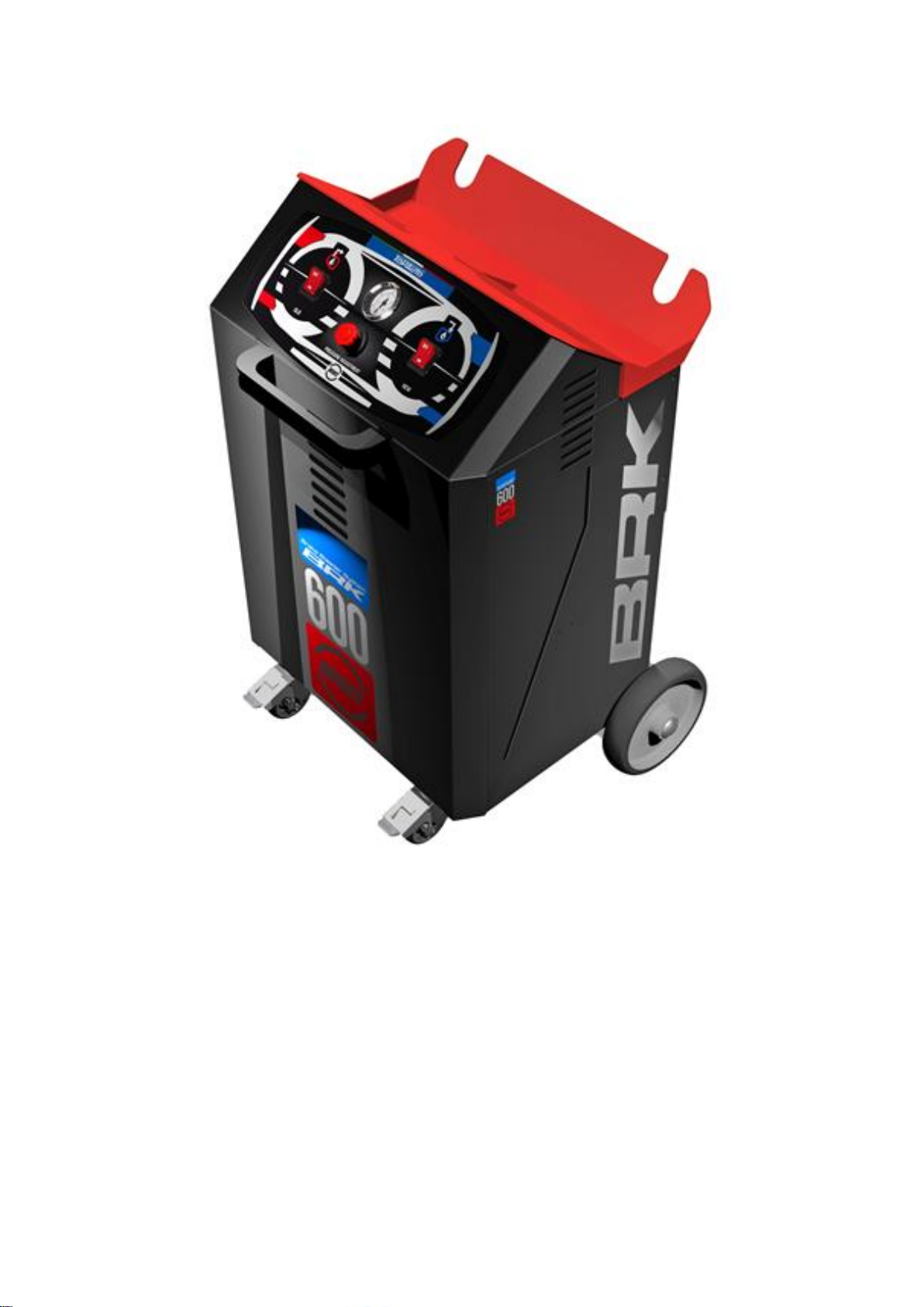
Top Auto BRK600 User manual
USERMANUAL
MAINTENANCEANDSPAREPARTS
BRAKEBLEEDER
BRK600

USER MANUAL, MAINTENANCE AND SPARE PARTS
Rev. 01-2020
PAGE. 2
BRK600

USER MANUAL, MAINTENANCE AND SPARE PARTS
Rev. 01-2020
PAGE. 3
BRK600
1 INTRODUCTION ............................................................................................................................... 5
1.1 PURPOSE OF THE INSTRUCTION MANUAL................................................................................................5
1.2 HOW TO READ AND USE THE INSTRUCTION MANUAL ..............................................................................5
1.3 PRESERVATION OF THE MANUAL.............................................................................................................5
1.4 MANUAL INSTRUCTION UPDATE..............................................................................................................5
1.5 RECIPIENTS .............................................................................................................................................5
1.6 SYMBOLOGY ......................................................................................................................................6
2 GENERAL INFORMATION.......................................................................................................... 6
2.1 MANUFACTURER IDENTIFICATION DATA..................................................................................................6
2.2 MACHINE IDENTIFICATION DATA.............................................................................................................6
2.3 CE MARKING...........................................................................................................................................6
2.4 GENERAL SAFETY RULES ..........................................................................................................................7
2.5 BRAKE FLUIDS - PERSONAL PROTECTIVE EQUIPMENT AND PRECAUTIONS.................................................8
2.5.1 FIRST AID MEASURES .....................................................................................................................................................8
2.5.2 FIRE-FIGHTING MEASURES.............................................................................................................................................8
2.5.3 MEASURES IN THE EVENT OF AN ACCIDENTAL LEAK .....................................................................................................8
2.6 WARRANTY.............................................................................................................................................9
2.7 DURATION OF WARRANTY ......................................................................................................................9
3 MACHINE DESCRIPTION ................................................................................................................. 10
3.1 OPERATING PRINCIPLES.........................................................................................................................10
3.2 MACHINE COMPONENTS.......................................................................................................................10
3.3 TECHNICAL SPECIFICATIONS ..................................................................................................................11
4 OPERATION AND USE..................................................................................................................... 12
4.1 DESCRIPTION OF THE MACHINE OPERATION..........................................................................................12
4.2 MACHINE CYCLES ..................................................................................................................................12
4.3 INTENDED AND UNINTENDED USE.........................................................................................................12
4.4 WORKSTATIONS FOR OPERATORS .........................................................................................................12
5 INSTALLATION ............................................................................................................................... 13
5.1 DELIVERY AND CONTROL.......................................................................................................................13
5.2 MACHINE SETUP ...................................................................................................................................13
6 MACHINE USE................................................................................................................................ 14
6.1 PROBLEMS AND REMEDIES....................................................................................................................17
7 MAINTENANCE .............................................................................................................................. 18
7.1 NATURE AND FREQUENCY OF CHECKS AND MAINTENANCE....................................................................18

USER MANUAL, MAINTENANCE AND SPARE PARTS
Rev. 01-2020
PAGE. 4
BRK600
7.2 EXHAUSTED OIL TANK EMPTYING ..........................................................................................................18
8 ADDITIONAL INSTRUCTIONS........................................................................................................... 18
8.1 DEACTIVATION AND DISASSEMBLY........................................................................................................18
9 SPARE PARTS ................................................................................................................................. 19
9.1 GENERAL INSTRUCTIONS .......................................................................................................................19
9.2 SPARE PARTS REQUEST FORM ...............................................................................................................19
9.3 SPARE PARTS LIST..................................................................................................................................20
10 ELECTRICAL DIAGRAM.................................................................................................................. 23
11 HYDRAULIC DIAGRAM.................................................................................................................. 24
12 SERVICE-PROGRAM...................................................................................................................... 25

USER MANUAL, MAINTENANCE AND SPARE PARTS
Rev. 01-2020
PAGE. 5
BRK600
1 INTRODUCTION
1.1 PURPOSE OF THE INSTRUCTION MANUAL
This user and maintenance manual contains data concerning the performance, technical characteristics, use and maintenance
methods for the standard and correct operation of the machine.
The user is recommended to read it carefully and to comply with the rules and procedures contained in it, as they provide important
indications regarding the safety of use.
This will allow to optimize the operation, increase the duration of the machine, and operate safely.
Failure to comply with the suggested rules can cause malfunctions, anomalies, or damages; the machine must therefore be
intended only for the use for which it was expressly designed.
The manufacturing company will not be held responsible for breakages, accidents, or various inconveniences due to the non-
compliance (or in any case non-application) of the requirements contained in this manual. The same applies to the execution of
modifications, variations, and/or the installation of accessories, that were not authorized in advance.
1.2 HOW TO READ AND USE THE INSTRUCTION MANUAL
The machine was manufactured in accordance with all Community rules concerning the free movement of industrial products in
the countries of the European Community (check the Machinery Directive 2006/42/EC).
The machine is then provided complete with all the documentation required by these regulations.
The user manual, maintenance and spare parts is an integral part of it and contains all the information necessary for a good
operation of the machine with particular attention to the safety of the involved personnel.
1.3 PRESERVATION OF THE MANUAL
This instruction manual is an integral part of the machine and must therefore be carefully preserved for any further consultation.
1) It is recommended to use the manual carefully so as not to damage the content and not compromise its functionality.
2) Do not remove, tear or rewrite parts of the manual for any reason.
3) Store the manual in places protected from moisture and heat.
4) The user manual must be stored near the machine so that consultation is facilitated.
5) The place of preservation of the manual must be clearly identifiable and known to all operators authorized to use the machine.
6) Once the consultation has been completed, the manual must be stored in the appropriate place of storage.
7) The manual must be kept for the duration of use of the machine and transmitted to any other user or subsequent owner.
1.4 MANUAL INSTRUCTION UPDATE
The manufacturing company reserves the right to make changes, additions or improvements to the manual itself, without this
being a reason to consider this publication inadequate.
1.5 RECIPIENTS
This documentation is addressed to qualified and appropriately trained technical staff.
Only qualified personnel have the necessary technical knowledge to correctly interpret and apply concretely the safety regulations
and warnings contained in the specific documents.
Knowledge and correct application of safety regulations and warnings are prerequisites for the installation and setup free of
hazards as well as for safety during operation and maintenance of the described product.
"Qualified personnel" means those persons who, by reason of their training, experience, education, knowledge of the relevant
standards, requirements, measures for the prevention of accidents and conditions of service, have been authorized by the person
in charge for the safety concerning machineries to carry out any necessary activities and to be able to recognize and avoid any
possible danger.
USER MANUAL, MAINTENANCE AND SPARE PARTS
Rev. 01-2020
PAGE. 6
BRK600
1.6 SYMBOLOGY
The bold texts, preceded by this symbol, contain very important information/regulation regarding the good operation of the
machine. Failure to comply may result in:
- loss of the contractual warranty
- declination of responsibility by the manufacturing company.
The bold texts preceded by this symbol contain signsof possible dangers and important requirements to safeguard the safety
of the operator. Failure to comply may result in:
- risks to operator’s safety
- declination of responsibility by the manufacturing company.
2 GENERAL INFORMATION
2.1 MANUFACTURER IDENTIFICATION DATA
2.2 MACHINE IDENTIFICATION DATA
The machine is built in accordance with the Machinery Directive 2006/42/ currently in force for use within the European Community
in the safety field. The CE marking tags and related product identification data are affixed to the machine. The serial number must
also be used for the request of intervention or for spare parts.
The identification plate must always be kept legible with regard to all the data contained in it and must be periodically cleaned.
If the license plate deteriorates and/or is no longer legible, even in only one of the information elements reported, it is recom-
mended to request another one from the manufacturer, citing the data contained in this manual, and provide for its replacement.
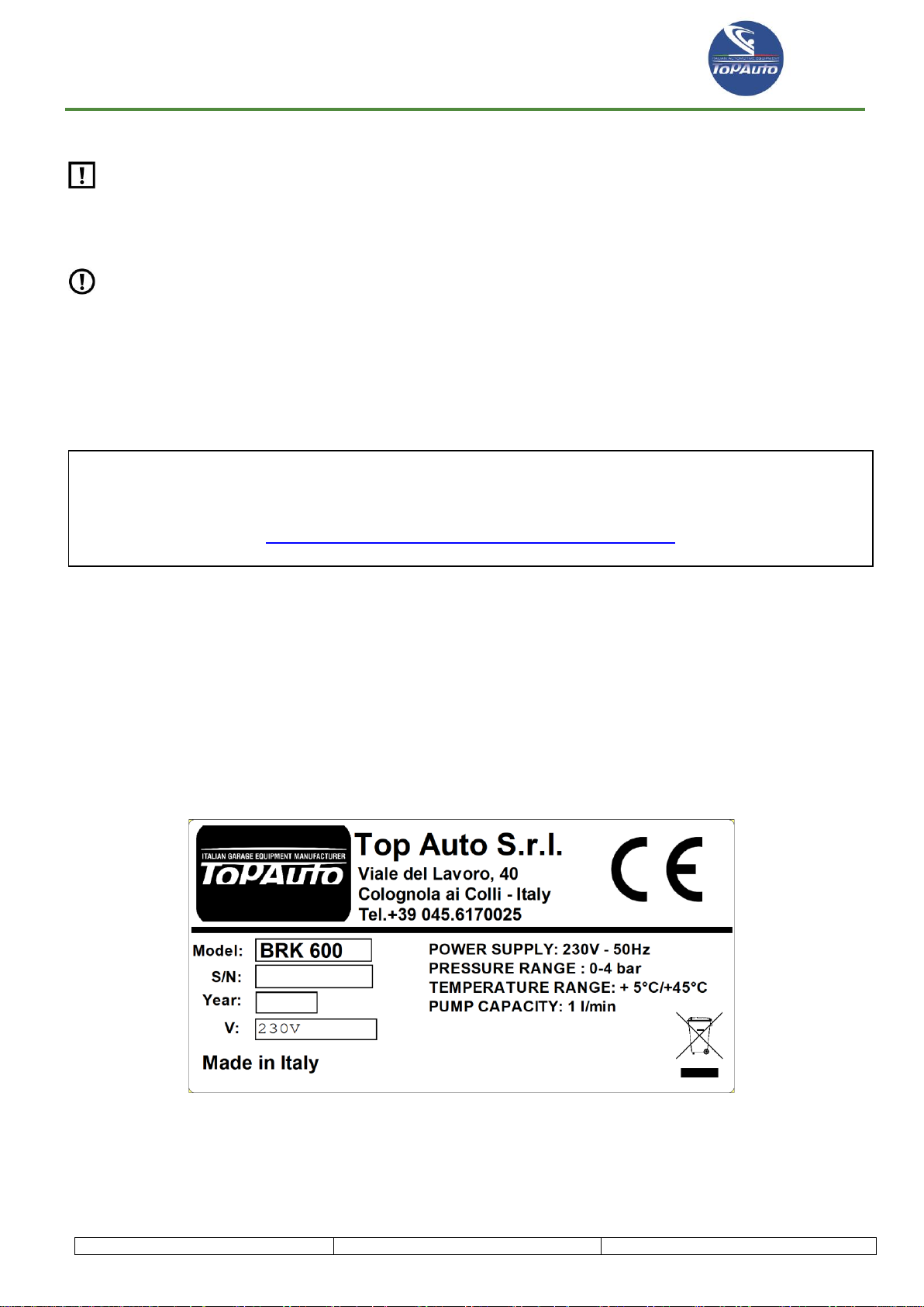
2.3 CE MARKING
MODEL: Machine Model
SERIAL NUMBER: Machine Serial Number
Top Auto S.r.l.
Viale del Lavoro 40, 37030 Colognola ai colli –Italy
tel. +39 0456170025 - fax. +39 6152493
info@topauto-equipment.com www.topauto-equipment.com

USER MANUAL, MAINTENANCE AND SPARE PARTS
Rev. 01-2020
PAGE. 7
BRK600
2.4 GENERAL SAFETY RULES
In addition to the rules listed below, the machinery supervisor must comply with the regulation of current legislation on the
safety and health of personnel at workplaces (Directive 2006/42/EC).
Always follow the safety regulations and instructions in this manual.
The manufacturing company disclaims all responsibility resulting from an incorrect use of the machine and the supplied
equipment.
The unit must not operate with liquids other than those for which the machine was built.
The machine must be used by qualified personnel and can be used correctly only after reading this manual containing also
the basic safety rules set out below:
Wear gloves and goggles.
Do not expose the machine to direct sunlight and rain.
Before any operation check on the vehicle use and maintenance manual the type of fluid used by the braking system.
Do not smoke near the machine and during operations.
Do not use the machine in environments without lightning protection.
The equipment is classified in: Group II category 3G II B T3 and must be used in places with classification 2. The environmental
conditions of use of the equipment are as follows:
pressure from 80 kPa (0.8 bar) to 110 kPa (1.1 bar);
temperature from –20°C to + 60°C;
air with normal oxygen content, usually 21 % v/v.
The machine shall not be used in places at risk of explosion and/or fire classified in the following areas:
1. zone 0 –20 / 1 –21;
2. maximum operating temperatures T4, T5 and T6.
Machine storage: the machine, when not used, must be stored in a dedicated place having the following characteristics:
1. There must be no trigger sources, such as heat sources, open flames, sparks of mechanical origin, electrical equipment,
stray electric currents and cathodic corrosion (verify that the electrical distribution system complies with the laws in force); (check
the grounding of the plant's electrical distribution system).
Use the machine away from heat sources, open flames and/or sparks.
Always make sure that when you turn off the engine the vehicle ignition key is brought to the “All Off (OFF)”position.
Keep connection pipes away from moving or rotating objects/elements.
Keep connection pipes away from hot objects/elements.
Always make sure that the liquid tank is at the correct level.
Before connecting the machinewith the power grid, check that the voltage and the frequency of the power supply corresponds
to the values indicated in the CE marking.
Always check that the exhausted fluid tank is not full before starting each operation
Throw the extracted liquid in the appropriate containers for exhausted oils.
Check frequently that the two filters on the device are not obstructed.
Use only the liquids recommended by the manufacturer.
Failure to comply with each of the above safety rules results in the decay of any form of warranty on the machine.

USER MANUAL, MAINTENANCE AND SPARE PARTS
Rev. 01-2020
PAGE. 8
BRK600
2.5 BRAKE FLUIDS - PERSONAL PROTECTIVE EQUIPMENT AND PRECAUTIONS
The operator must wear appropriate protections such as goggles, gloves, and clothing suitable for work.
2.5.1 FIRST AID MEASURES
Inhalation
If inhaled, go quickly to the open air. If symptoms appear ask for medical assistance. In case of
inhalation of decomposed products in a fire, symptoms may be delayed. It is possible that the ex-
posed person shall be kept under medical supervision for 48 hours.
Contact with the
skin
Skin degreasing. It can cause dryness and skin irritation.
Eye contact
Not classified as eye irritant. Based on the documentation available for this or other similar materials.
Ingestion
Diethylene glycol: ingestion of diethylene glycol can cause metabolic acidosis, kidney damage, cen-
tral nervous system depression and convulsions. The estimated lethal dose for an adult is circa 100
ml.
Main symptoms and
effects, both acute
and delayed
Overexposure to inhalation of drops in the air or aerosols can cause irritation of the respiratory tract.
Ingestion of large amounts can cause nausea and diarrhea.
Prolonged or repeated contact with the skin may over-degrease the skin and cause irritation and/or
dermatitis.
Potential risk of burning or temporary redness in case of accidental eye contact.
2.5.2 FIRE-FIGHTING MEASURES
Usable means for
extinguishing a fire
In case of fire, use sprays or fire extinguishers based on foam, anhydrous chemicals, or carbon
dioxide.
Special hazards
arising from the
substance or the
mixture
Exposure to flames can cause the container to break or explode.
Dangerous combustion products: in the event of fire, the following products may result by thermal
decomposition:
Carbon monoxide, carbon dioxide, nitrogen monoxide, nitrogen dioxide
Recommendations
for people in charge
of fire extinguishing
No action should be taken involving any personal risk or without appropriate training. Promptly isolate
the area by moving all people away from the accident area in the event of a fire.
Special protective
equipment for fire-
fighters
Firefighters must wear protective equipment and a self-contained breathing apparatus (SCBA) with
full face mask on the face operating at positive pressure. Clothing for firefighters (including helmets,
protective boots, and gloves) that comply with the EN 469 European standard will ensure basic level
protection for chemical accidents.
2.5.3 MEASURES IN THE EVENT OF AN ACCIDENTAL LEAK
Small leak
Stop the leakage if there is no risk. Move containers away from the leakage area. Absorb with an
inert material and put the spilled product in a special recovery container. Dispose of waste through
an authorized company for waste disposal.
Big leak
Stop the leakage if there is no risk. Move containers away from the leakage area. Prevent the leak-
age in sewer systems, waterways, bases, or limited areas. Circumscribe and collect any leak with
non-combustible absorbent material, such as sand, soil, vermiculite, diatomite and dispose of the
product in a container in accordance with the current legislation. Dispose of waste through an au-
thorized company for waste disposal.

USER MANUAL, MAINTENANCE AND SPARE PARTS
Rev. 01-2020
PAGE. 9
BRK600
Environmental pre-
cautions
Avoid dispersion and outflow of any spilled material and contact with waterways, drains and sew-
ers. Inform the relevant authorities if the product has caused environmental pollution (sewers, wa-
terways, land or air).
2.6 WARRANTY
The terms and conditions of the warranty are established as follows unless otherwise specified in the Order Confirmation:
Subject of the Warranty
The manufacturing company guarantees the good quality and good construction of the machine it builds, forcing itself, during
the specified warranty period, to repair or replace free of charge the parts whose premature breakage or wear are due to poor
quality of the materials used, defect in processing or imperfect assembly.
The warranty of those parts whose breakage or wear are due to:
Failure to comply with the instructions contained in the User and Maintenance Manual.
Lacking or incorrect maintenance.
Lacking or incorrect cleaning of all the components of the machine that need to be cleaned regularly.
User’s negligence related to level control, filters cleaning, auxiliary services, power supply.
Use of tools not suitable to perform ordinary and extraordinary maintenance.
Modifications or tampering carried out by the user or carried out by third parties, without specific approval by the manufac-
turing company.
Use of non-original spare parts.
2.7 DURATION OF WARRANTY
For warranty terms, reference is made to what is contractually agreed.

USER MANUAL, MAINTENANCE AND SPARE PARTS
Rev. 01-2020
PAGE. 10
BRK600
3 MACHINE DESCRIPTION
3.1 OPERATING PRINCIPLES
The machine referred to in this manual was designed and built to bleed the braking system in a single series of operations, with-
out any dispersion into the environment of brake fluids present in the vehicle braking system.
3.2 MACHINE COMPONENTS
1 –Carrying handle 8 –Polysnap module
2 –EXTRACTION PUMP ON / OFF button 9 –Connection for the extraction pipe
3 –Pressure regulator 10 –Clamp for charging pipe at rest
4 –Pressure gauge 11 –Clamp for extraction pipe at rest
5 –CHARGING PUMP ON / OFF button 12 –Extracted exhausted fluid tank
6 –Connection for the charging pipe 13 –Tank
7 –Handling wheels 14 –Space for accessories briefcase

USER MANUAL, MAINTENANCE AND SPARE PARTS
Rev. 01-2020
PAGE. 11
BRK600
3.3 TECHNICAL SPECIFICATIONS
Compatible fluid types
Pre-DOT –DOT2 –DOT3 –DOT4 –DOT5 –
DOT5.1 –DOT6 –DOT6.1 - LHM
Exhausted fluid tank capacity
5 l
New fluid tank capacity
5 l standard (predisposition for tanks up to 25 lt)
Operating pressure
0 –4 bar
Extraction pump power
30 W (1 l/min)
Charging pump power
30 W (1 l/min)
Charging/extraction pipe length
7,5 m
Power supply
230/50-60 Volt/Hz
Machine size
67x54x90H cm
Pack size
Unladen weight
Noise
< 70 dB (A)

USER MANUAL, MAINTENANCE AND SPARE PARTS
Rev. 01-2020
PAGE. 12
BRK600
4 OPERATION AND USE
4.1 DESCRIPTION OF THE MACHINE OPERATION
The machine referred to in this manual has been designed and built for the replacement and discharge of brake fluid from brake
and car clutch systems. The liquid is constantly pumped into the brake liquid tank with a pressure of 0 to 4 bar. The liquid to be
replaced can therefore be discharged through the individual bleeding valves of brake calipers until the new liquid comes out. This
technique avoids the formation of air bubbles in the system and avoids the typical annoying pouring operations.
4.2 MACHINE CYCLES
1) Extraction
The pump extracts the exhausted brake fluid from the specific pan in the engine compartment until completely emptied.
2) Connection
The adapter ca be found in the specific kit and connects to the pan instead of the original cap.
3) Charging new liquid
The pan is filled up to the expected level.
4) Bleeding old liquid
The exhausted liquid is extracted from the system through the bleeding valves.
5) Disconnection
The pressure is bled by the specific valve and the adapter is disconnected by putting the original cap back on the pan.
4.3 INTENDED AND UNINTENDED USE
The machine in question has been designed and built for the above use. The machine must not be used for uses other than those
specified here.
It is forbidden to:
Use the machine with a different liquid than the indicated one in this manual.
Modify the operation principle of the machine in any way by adding or removing components to it.
Use the machine in explosive and/or fire-risk environments.
Plug in the machine to energy sources other than those envisaged by the manufacturer
Use commercial devices for a purpose other than the manufacturer intended.
ATTENTION It is the obligation of the employer (or safety officer) to ensure that the machine is not used improperly,
endangering the health of the operator and exposed persons. It is the worker's obligation to inform the employer (or the
safety officer) if there is a danger of improper use of the machine because, as an educated person, the worker is respon-
sible for the machinery use he is going to carry on.
4.4 WORKSTATIONS FOR OPERATORS
The machine is designed to work in the presence of an operator. The presence of an operator is provided for the connection
and disconnection of the machine to the vehicle as well as to setup and switch off the cycle.
The dismantling of the protective casings and the consequent access inside the machine is provided only for maintenance and
cleaning operations.

USER MANUAL, MAINTENANCE AND SPARE PARTS
Rev. 01-2020
PAGE. 13
BRK600
5 INSTALLATION
5.1 DELIVERY AND CONTROL
Once the machine leaves the production plant of the Manufacturing company, any damage to it is attributable to the carrier, be
it a courier or a means of the buyer, unless otherwise specified in the Order Confirmation.
In case of damage to the machine, please inform the Manufacturing company as soon as possible.
At the time of delivery it is therefore necessary to check:
The match between packing list and the actual contents of the packaging.
The integrity of the packaging in all its parts, in order to identify any obvious damage attributable to the carrier.
Any damage reported by the machine as a result of incorrect execution of the carrier.
Contents of the packaging:
1 unit for the replacement of brake fluids
1 spiral charging pipe L= 7.5 m
1 spiral extraction pipe with filter L= 7.5 m
1 T-coupling to connect to adapters.
1 transparent pipe with rubber seal for bleeding valves connection L= 1 m
2 tanks (2 lt) for exhausted liquid bleeding
1 tank (10 lt) for extracted exhausted liquid.
1 tank (10 lt) for new liquid
5 adapters of various sizes
1 universal adapter
1 power cord
5.2 MACHINE SETUP
The machine is supplied fully assembled and tested. Before use, it is necessary to proceed with the preparation of the machine:
1) Connection of the charging pipe
Connect the spiral charging pipe with the
T-coupling to the right connector of the machine
2) Connection of the extraction pipe
Connect the spiral extraction pipe with the filter
to the left connector of the machine

USER MANUAL, MAINTENANCE AND SPARE PARTS
Rev. 01-2020
PAGE. 14
BRK600
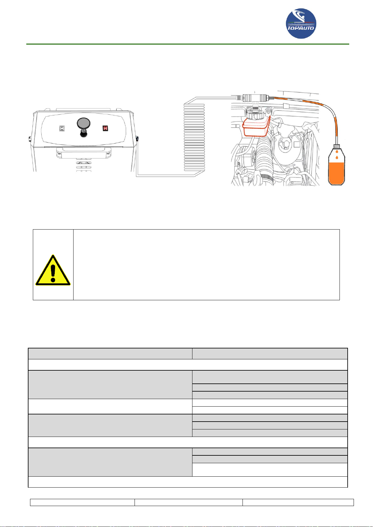
6 MACHINE USE
1. Identify the brake liquid pan 2. Remove the pan cap.
located in the motor engine.
3. Insert the extraction pipe into the pan and press the ON button to start the pump and extract all the exhausted liquid.
Stop the pump by pressing the OFF button when you start extracting air.

USER MANUAL, MAINTENANCE AND SPARE PARTS
Rev. 01-2020
PAGE. 15
BRK600
4. Identify the specific adapter and connect it to the pan making sure it is fixed correctly to avoid leakage during subse-
quent operations.
5. Connect the charging pipe to the adapter and press the ON button to start charging the new liquid.
Through the pressure regulator set the working pressure (usually 1.5 –2 bar)
USER MANUAL, MAINTENANCE AND SPARE PARTS
Rev. 01-2020
PAGE. 16
BRK600
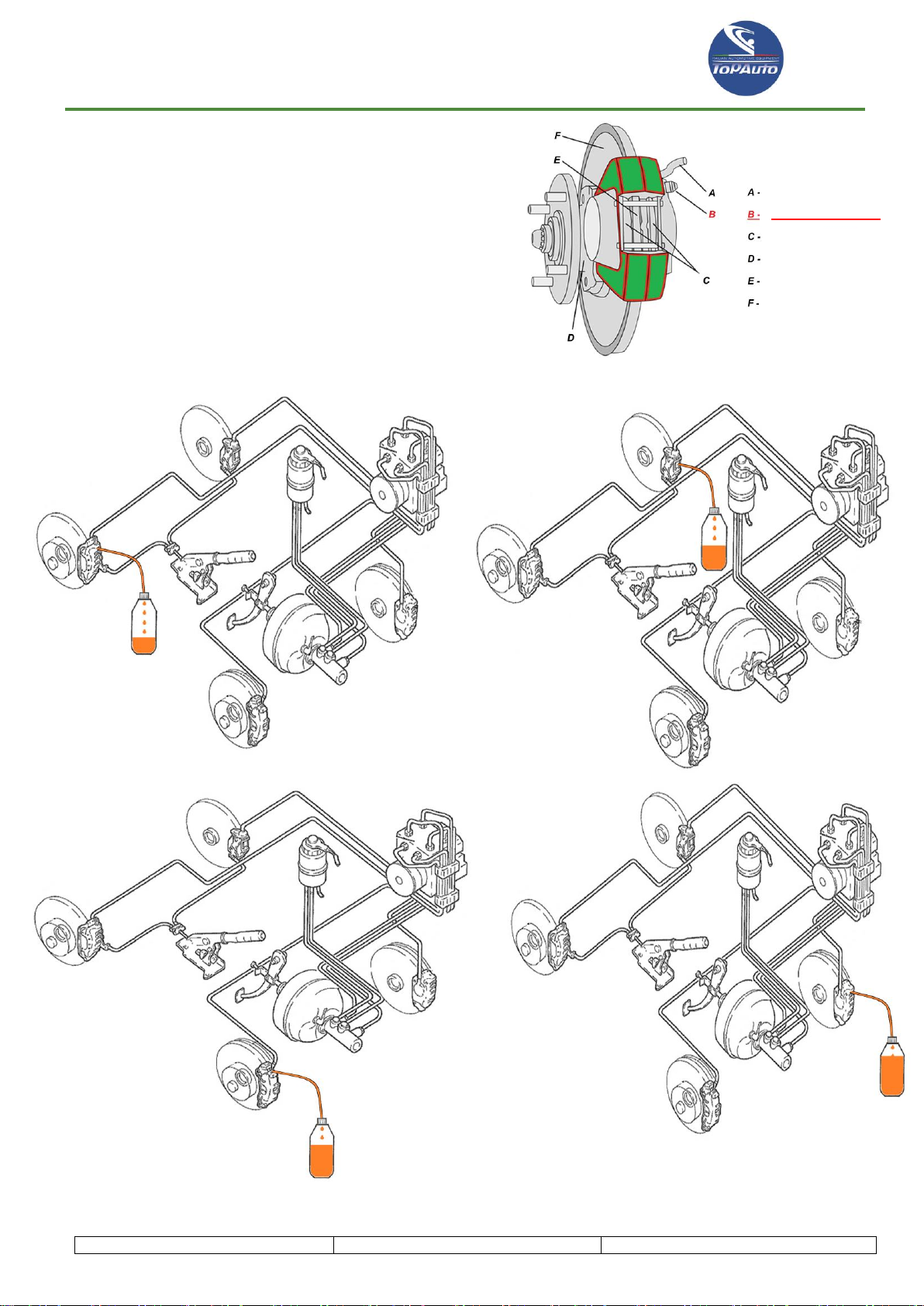
6. Use the pipette with the transparent tube and the 5l tank
supplied to connect to the valve.
Use a wrench to open the bleeding valve until you
see that the exhausted liquid comes out.
Bleeding is considered finished when new liquid comes out
from the transparent pipe. Then close the bleeding valve and
switch to the next brake caliper.
Carry out the bleeding operation on all 4 brake calipers.
Brake fluid pipe
BLEEDING VALVE
Piston
Hub
Brake pad
Disk
USER MANUAL, MAINTENANCE AND SPARE PARTS
Rev. 01-2020
PAGE. 17
BRK600
7. Once the bleeding operation is finished, turn off the machine via the OFF button.
8. Connect the pipette with the transparent pipe and the 5l tank to the T-coupling bleeding valve to bleed the pressure in
the charging pipe before disconnecting it.
9. Make sure the liquid inside the pan is at the correct level.
10. Disconnect the adapter and screw the original pan cap again.
ATTENTION!!!
When performing the brake bleeding operation on cars that are over 5 years old or that
still show signs of wear, it is absolutely advisable to replace the hoses that take the oil
to the brake calipers. In fact, maintenance on the braking system involves a restoration
of the original pressure. This pressure may be excessive for the old hoses, which may
break causing the liquid to spill and consequent malfunction of the braking system
with serious danger while driving.
6.1 PROBLEMS AND REMEDIES
The search for faults and the eventual repairing operations require compliance with ALL SAFETY PRECAUTIONS indicated in
Chapter 2.
PROBLEM
REMEDY
General problems
The machine does not work, the two ON/OFF switches do not
light up
Check the 2 line fuses (those mounted in the polysnap mod-
ule)
Check the power cord
Check the connection of the two ON/OFF buttons
When turned on, only one of the two ON/OFF buttons lights up
Check the connection of the not working button
Replace the not working button
The machine works but the pumps do not start
Check pump connection
Check the connection of thermal protectors
Replace pumps *
Problems with exhausted liquid extraction
The pump starts but extracts very slowly
Clean the filter on the extraction pipe
Check the correct operation of the non-return valve
Check that there is no narrowing on the pipes inside the ma-
chine
Problems with the new liquid charge
USER MANUAL, MAINTENANCE AND SPARE PARTS
Rev. 01-2020
PAGE. 18
BRK600
The pump starts but struggles to charge the new liquid
Clean the filter on the pipe that goes into the new liquid tank
Check the correct operation of the non-return valve
Check that there is no narrowing on the pipes inside the ma-
chine
Problems with pressure regulation
The machine does not reach the set pressure
Check that the adapter on the pan is connected correctly and
that there are no leaks
Replace pressure regulator *
* CONTACT THE MANUFACTURER'S SUPPORT SERVICE.
7 MAINTENANCE
ALL MAINTENANCE OPERATIONS MUST BE CARRIED OUT WHEN THE MACHINE IS STATIONARY.
7.1 NATURE AND FREQUENCY OF CHECKS AND MAINTENANCE
To keep the unit in full efficiency, you must follow the stated maintenance timelines.
FAILURE TO COMPLY WITH THE ABOVE STATEMENTS EXEMPTS THE MANUFACTURER FROM ANY RESPONSI-
BILITY TO THE EFFECTS OF THE WARRANTY.
AFTER 1 WEEK after the setup, you must check:
The correct tightening of the screws;
The correct tightening of the pipes;
The absence of leaks in the machine.
EVERY 6 MONTHS you must check:
The correct tightening of the screws;
The correct tightening of the pipes;
The integrity of the connection pipes;
The cleaning of the two filters;
The absence of leaks in the machine.
ATTENTION! The brake fluid must not be discharged in the environment; it is a special waste and as such it must
be disposed of in accordance with the rules in force.
7.2 EXHAUSTED OIL TANK EMPTYING
When the level of the exhausted liquid in the tank exceeds half, it must be emptied in order to avoid leaks. Remove the tank with
the exhausted liquid very carefully. Unscrew the cap and empty the tank into another tank for exhausted oils. Screw the tank cap
again and place it in its location.
8 ADDITIONAL INSTRUCTIONS
8.1 DEACTIVATION AND DISASSEMBLY
According to Directive 2012/19/EU, the machine cannot be disposed of through municipal waste, but is required to be delivered
to a specialised centre for the separate collection and disposal of Waste Electrical and Electronic Equipment (WEEE), or it can
be returned to the retailer in case of purchase of a new machine. The law provides for sanctions for those who release WEEE into
the environment. WEEE, if released into the environment or misused, can release substances that are dangerous to the environ-
ment itself and to human health.

USER MANUAL, MAINTENANCE AND SPARE PARTS
Rev. 01-2020
PAGE. 19
BRK600
9 SPARE PARTS
9.1 GENERAL INSTRUCTIONS
For the replacement of spare parts use only ORIGINAL SPARE PARTS.
The use of non-original spare parts entails the immediate suspension of the warranty; in addition, the manufacturing company
disclaims all responsibility concerning the machinery safety in case of accidents.
The manufacturing company put its technicians in its factory at customers’ disposal, to solve any problems regarding the use
and maintenance of the machine.
To order a spare part, it is advisable to use the attached form below, which must be completed in all its parts.
The following is a list of the individual pieces, the number corresponding to the position occupied in the attached drawings, the
code and the description.
Orders (which must be sent by fax or e-mail) must be addressed to:
9.2 SPARE PARTS REQUEST FORM
The next page shows the form to be used to order spare parts.
In the case of a request for spare parts or a request for a quote for spare parts, it is advisable to photocopy the form and fill it out
in all its parts.
The detailed compilation is decisive to receive a prompt response from the Technical Assistance Support of the Manufacturing
company.
DRAWING NO.
POS
CODE - DESCRIPTION
QUANTITY
SPARE PARTS REQUEST FORM
CUSTOMER:
MACHINE:
SERIAL NUMBER:
YEAR OF MANUFACTURE:
SHIPPING ADDRESS:
TELEPHONE:
FAX:
Top Auto S.r.l.
Viale dell'Artigianato 4, 37042- Caldiero (VR) –Italy
tel. +39 0456170025 - fax. +39 0456152493
info@topauto-equipment.com www.topauto-equipment.com

USER MANUAL, MAINTENANCE AND SPARE PARTS
Rev. 01-2020
PAGE. 20
BRK600
9.3 SPARE PARTS LIST
Table of contents
Other Top Auto Automobile Accessories manuals

Popular Automobile Accessories manuals by other brands


ULTIMATE SPEED
ULTIMATE SPEED 279746 Assembly and Safety Advice

SSV Works
SSV Works DF-F65 manual

ULTIMATE SPEED
ULTIMATE SPEED CARBON Assembly and Safety Advice

Witter
Witter F174 Fitting instructions

WeatherTech
WeatherTech No-Drill installation instructions

TAUBENREUTHER
TAUBENREUTHER 1-336050 Installation instruction