Top Tronic TEL28 User manual

INSTRUCTION MANUAL
LEAKAGE TESTER
DIGITAL EARTH
OFF
SELECT
Min
Current
Adjust
Max
ENTER - YES
TEST - ON
AUTO-OFF
LINE
AUTO POWER OFF
MULTI VOLTAGE
50Hz
EARTH
Battery
OK CAT 450V
DIGITAL RCCB / ELCB TESTER
TEL28

1. SAFETY PRECAUTIONS
Electricity can cause severe injuries even with low
voltages or currents.
Therefore it is extremely inportant that you read
the following information before using your Digital
RCCB / ELCB Tester.
1.1 This Instrument must only be used and operated
by a competent trained person and in strict
accordance with the instructions.
We will not accept liability for any damage or injury
caused by misuse or non compliance with
instructions and safety procedures.
1.2 Never open Your Digital RCCB / ELCB Tester
except for battery replacement. ( See Battery
replacement section ).
1.3 Always inspect you Digital RCCB / ELCB tester
and test leads before use for any sign of
abnormality or damage. If any abnormal conditions
exist ( broken test leads, cracked case, display
faulty etc... ) do not attempt to take any
measurement or use the tester.
Return your Digital RCCB / ELCB tester to your
nearest Distributor for Service.
1.4 Never replace the protective fuse with any other
than the specified or approved equivalent.
1.5 Your Digital RCCB / ELCB tester has been
designed with your safety in mind. However, no
design can completely protect against incorrect
use. Electrical circuits can be dangerous and/or
lethal when a lack of caution or poor safety
practice is used. Use caution in the presence of
voltage above 24V as these pose a shock hazard.
-1-
INDEX Page
SAFETY PRECAUTIONS ............................. 1-2
SPECIFICATIONS ........................................ 3
FEATURES ................................................... 4
CONNECTIONS ........................................... 4
INSTRUMENT LAYOUT ............................... 5
LID INSTRUCTIONS..................................... 6
RCCB / ELCB TESTING - SENSITIVITY ..... 7
RCCB / ELCB TESTING - TIME DELAY - .... 8
PREPARATION FOR MEASUREMENT ....... 9
BATTERY REPLACEMENT .......................... 9
FUSE REPLACEMENT ................................ 9
SERVICING AND CALIBRATION.................. 10
-2- -3-
1.6 Pay attention to cautions and warnings which
will inform you of potentially dangerous
procedures.
1.7 Rated environmental conditions
(1) Indoor use.
(2) Installation Category .
(3) Pollution Degree 2.
(4) Altitude up to 2000 Meter.
(5) Relative Humidity 80% Max.
oo
(6) Ambient Temperature 0 ~40 C.
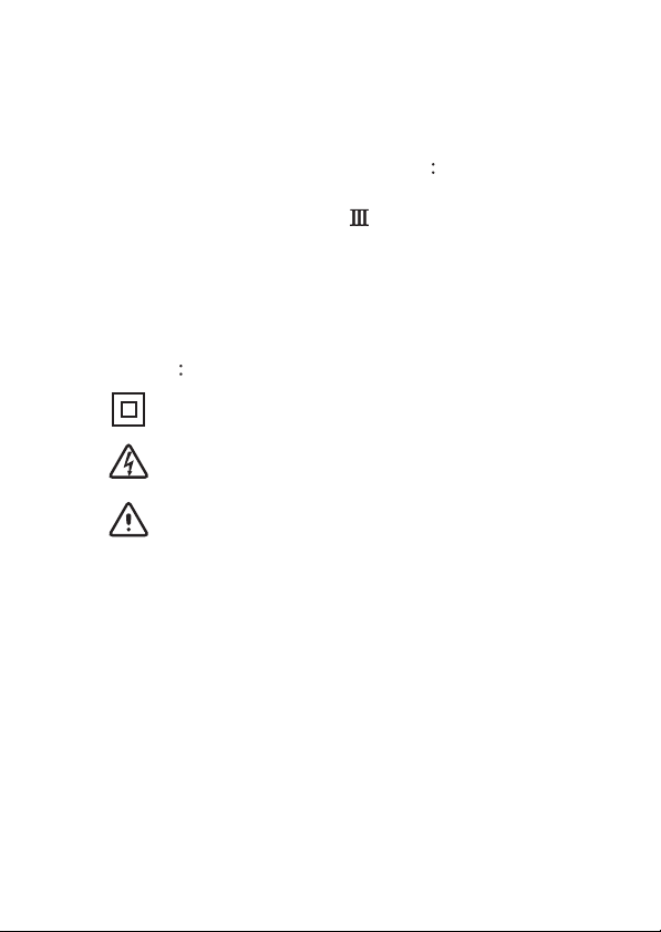
1.8 Observe the International Electrical Symbols listed
below
Meter is protected throughout by double
insulation or reinforced insulation.
Warning ! Risk of electric shock.
Caution ! Refer to this manual before using
the meter.
Alternating current.
~
2.SPECIFICATIONS
Current Settings 0-999mAac / 50Hz
Current Selection Knob
Phase Start Selection Referenced to Earth
0°and 180°Yes
Over-Temperature Protection Yes
Phase Polarity Trip Indicator Referenced to Earth
Yes
Operating Voltage ( L-E ) 110Vac to 450Vac
Timer Resolution 1mS (Max Time = 9.999S)
Timer Accuracy 1mS ±1mS
Current Accuracy ±1% ± 1mA
Current Resolution 1mA
Voltmeter Accuracy (50Hz) 50-350 Vac = ±2% ±1V
350-450Vac = ±5% ±1V
Voltmeter Resolution 1V
Operating Temperature -5°C ~ 45°C
Storage Temperature -10°C ~ 85°C
Battery 8 x AA batteries
Power Source Bat OK Led lit if >7.5V
Maximum Current Specified at 450Vac / 50Hz

-2- -3-
1.6 Pay attention to cautions and warnings which
will inform you of potentially dangerous
procedures.
1.7 Rated environmental conditions
(1) Indoor use.
(2) Installation Category .
(3) Pollution Degree 2.
(4) Altitude up to 2000 Meter.
(5) Relative Humidity 80% Max.
oo
(6) Ambient Temperature 0 ~40 C.
1.8 Observe the International Electrical Symbols listed
below
Meter is protected throughout by double
insulation or reinforced insulation.
Warning ! Risk of electric shock.
Caution ! Refer to this manual before using
the meter.
Alternating current.
~
2.SPECIFICATIONS
Current Settings 0-999mAac / 50Hz
Current Selection Knob
Phase Start Selection Referenced to Earth
0°and 180°Yes
Over-Temperature Protection Yes
Phase Polarity Trip Indicator Referenced to Earth
Yes
Operating Voltage ( L-E ) 110Vac to 450Vac
Timer Resolution 1mS (Max Time = 9.999S)
Timer Accuracy 1mS ±1mS
Current Accuracy ±1% ± 1mA
Current Resolution 1mA
Voltmeter Accuracy (50Hz) 50-350 Vac = ±2% ±1V
350-450Vac = ±5% ±1V
Voltmeter Resolution 1V
Operating Temperature -5°C ~ 45°C
Storage Temperature -10°C ~ 85°C
Battery 8 x AA batteries
Power Source Bat OK Led lit if >7.5V
Maximum Current Specified at 450Vac / 50Hz
LEAKAGE TESTER
DIGITAL EARTH
OFF
SELECT
Min
Current
Adjust
Max
ENTER - YES
TEST - ON
AUTO-OFF
LINE
AUTO POWER OFF
MULTI VOLTAGE
50Hz
EARTH
Battery
OK CAT 450V
-4- -5-
3. FEATURES
2 Lines x 16 Characters L.C.D.
Very Low Consumption.
Microprocessor Controlled.
.
Better than 3% accuracy. ( Current )
Menu Driven.
Accurate Digital readout of Disconnection Time.
Accurate Digital readout of Disconnection
sensitivity.
Data Hold Function.
Zero Crossing Circuitry permits testing at 0° or 180°.
Disconnection Phase Polarity Shown on L.C.D.
display.
Auto-Off and Off override.
Polarity Trip Indicator ( Positive or Negative Phase ).
EN/IEC 61010-1 CAT 450V
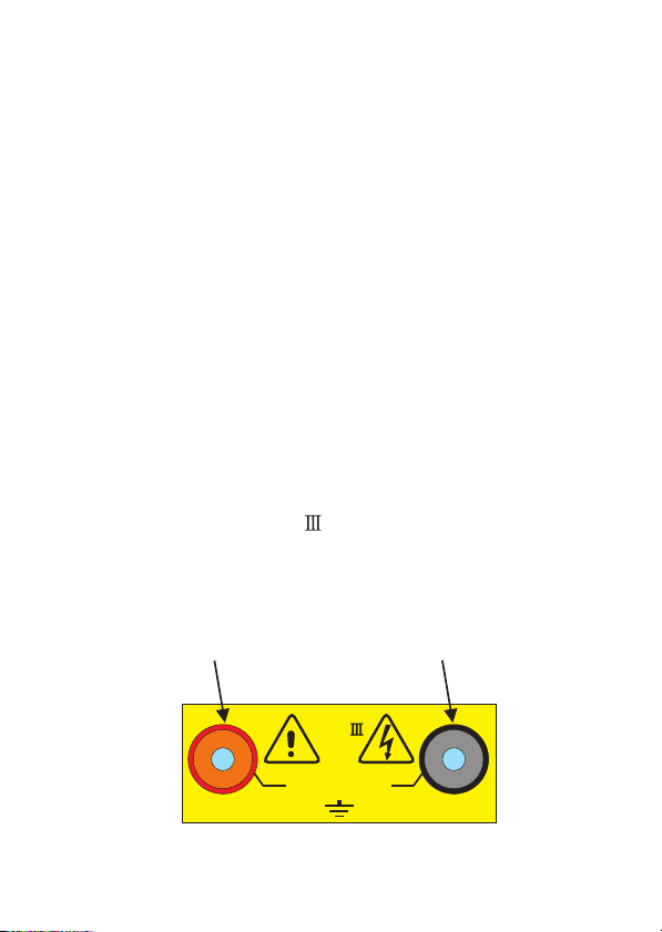
4. CONNECTIONS
Ÿ
Ÿ
Ÿ
ŸSuitable for industrial applications
Ÿ
Ÿ
Ÿ
Ÿ
Ÿ
Ÿ
Ÿ
Ÿ
Ÿ
Ÿ
LINE EARTH
Line Probe
Connection
Earth Probe
Connection
CAT
MAX ~ 450V
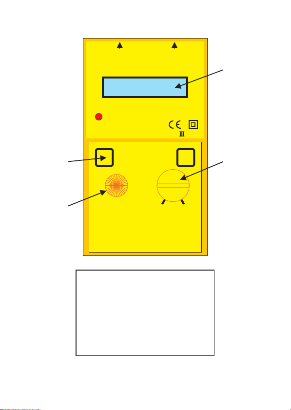
1
23
4
1.On Switch.-
Yes / Accept Button Switch.
2.Selection Switch.
Instantaneous - Time Delay
0°- 180°
3.Current Selection Knob.
4.Intelligent L.C.D.
5. INSTRUMENT LAYOUT
LEAKAGE TESTER
DIGITAL EARTH
OFF
SELECT
Min
Current
Adjust
Max
ENTER - YES
TEST - ON
AUTO-OFF
LINE
AUTO POWER OFF
MULTI VOLTAGE
50Hz
EARTH
Battery
OK CAT 450V
-4- -5-
3. FEATURES
2 Lines x 16 Characters L.C.D.
Very Low Consumption.
Microprocessor Controlled.
.
Better than 3% accuracy. ( Current )
Menu Driven.
Accurate Digital readout of Disconnection Time.
Accurate Digital readout of Disconnection
sensitivity.
Data Hold Function.
Zero Crossing Circuitry permits testing at 0° or 180°.
Disconnection Phase Polarity Shown on L.C.D.
display.
Auto-Off and Off override.
Polarity Trip Indicator ( Positive or Negative Phase ).
EN/IEC 61010-1 CAT 450V
4. CONNECTIONS
Ÿ
Ÿ
Ÿ
ŸSuitable for industrial applications
Ÿ
Ÿ
Ÿ
Ÿ
Ÿ
Ÿ
Ÿ
Ÿ
Ÿ
Ÿ
LINE EARTH
Line Probe
Connection
Earth Probe
Connection
CAT
MAX ~ 450V
1
23
4
1.On Switch.-
Yes / Accept Button Switch.
2.Selection Switch.
Instantaneous - Time Delay
0°- 180°
3.Current Selection Knob.
4.Intelligent L.C.D.
5. INSTRUMENT LAYOUT
6. LID INSTRUCTIONS
-6- -7-
INSTRUCTIONS
DIGITAL ELCB ( RCD ) TESTER
1.Insert the leads into Instrument. 4.Select positive or negative edge to start.
2.Select the test required: 5.follow interactive menu for connections.
Test 1= ELCB Sensitivity ( Instantaneous ELCB's ) 6.Test start Immediately when voltage is detected.
Test 2= Tripping Time ( time Delay & Invers Time 7.The test stops automatically when ELCB trips.
Delay ) ( voltage disappears ).
3.Select the current with the knob: 8. Test results are shown on the display.
Test 1 = ramp starting test current.
Test 2 = constant test current.
ELCB's
IMPORTANT
1.The tester check both the point at which the ELCB ( RCD ) trips ( TEST 1-mA ) as well as the time taken for a
given selected current ( TEST 2-mS ) to trip. Both tests show the phase at which tripping occurred.
2.The tester operates between Line and Earth. Ensure that L-E voltage does not exceed 450V.
3.The tester is protected against over-temperature. If over-Temperature message appears. Allow time for the
to cool down.tester
TEST 1 - Tripping Point (Sensitivity)
A ramp current rising in one mA steps is injected.
To save time and reduce power dissipation.The
starting point of the ramp may be selected.
The Instrument displays :
1. The Tripping point (mA) of the ELCB ( Sensitivity )
2. The Phase when tripping occurred.
3. The Voltage ( L-E ) at the start of the test.
Should the ELCB not trip within the current capability
of the instrument, the display will show 1=999mA and
"Hold>OVR", meaning the ELCB did not trip below
999mA. The tripping point is out of the Range of the
Instrument ( or ELCB faulty ) .
TEST 2 - Tripping Time of Breaker
A preselected constant current is introduced L-E
The Instrument displays :
1. The tripping time of the ELCB.
2. The phase when tripping occurred.
3. The voltage ( L-E ) at the start of the test.
Should the ELCB not trip within the testing time
capability of the instrument, the display will show
T=99.999s and "Hold>OVR", meaning the ELCB did
not trip below 99.999s. The tripping point is out of the
Range of the instrument ( or ELCB faulty ).
TEST PROCEDURE
7. RCCB / ELCB TESTING - SENSITIVITY
Turn Instrument "ON" by pressing the "TEST-ON" button.
The L.C.D. display will come to the following Screen.
Connect Leads to Earth and Phase.
Testing will startAutomatically when voltage is detected.
Test In Progress. The Voltage
between leads is 317V and I=127mA
Push Select to change Selection
to Instantaneous, then Press "TEST " to accept.
Dial the Starting Current of the
Instantaneous Test using the Current Adjust Knob.
Select the Positive or Negative
Start Edge using the Select Button.
TRP= Tripped, Display on Hold
Tripped at 140mA, on -edge of signal.
* - Instantaneous
- Time Delay
Dial Starting
Current. 123mA
Connect Leads
to Earth & Phase
V=317V
I=127mA
V=317V -
I=140mA Hold®TRP
Positive
Start Edge
0°
-8- -9-
8. RCCB / ELCB TESTING - TIME DELAY -
Turn Instrument "ON" by pressing the "TEST-ON" button.
The L.C.D. display will come to the following Screen.
Connect Leads to Earth and Phase. When voltage is
detected, Testing will start Automatically.
Test In Progress since 4.020s. The Voltage
between leads is 317V and Constant current is 125mA.
Push Select to change Selection
to Instantaneous, then Press "TEST " to accept.
Dial the Starting Current of the
Instantaneous Test using the Current Adjust Knob.
Select the Positive or Negative
Start Edge using the Select Button.
TRP= Tripped, Display on Hold
at 6.435s Tripped on +edge of signal.
- Instantaneous
- Time Delay*
Dial Starting
Current. 125mA
Connect Leads
to Earth & Phase
V=317V T=4.020s
I=125mA
V=317V + T=6.435s
I=125mA Hold®TRP
Positive
Start Edge
0°
9. PREPARATION FOR MEASUREMENT
Before testing Always Check the Following.
At Power "ON", check :
–The BAT OK led lit. If the BAT OK led does not lit,
replace batteries.
–There is no visual damage to the Instrument or Test
leads.
–Test lead Continuity with a continuity meter.
10. BATTERY REPLACEMENT
Your Digital RCCB / ELCB Tester's batteries are
situated under the tester.
The BAT OK led (if battery voltage >7.5V ) will
indicate when the battery need to be replaced ( if BAT
OK led does not lit when tester is on ).
Disconnect the Test leads from the Instrument,
remove the battery cover and the batteries.
Replace with eight 1.5V R6 or L6 batteries, taking
care to observe correct polarity.
Replace the Battery cover.
11. FUSE REPLACEMENT
The Fuse is located in the Battery compartment. To
replace the Fuse, proceed as per Battery
replacement to open the Battery cover, then remove
and replace the fuse located on the side of the
batteries . Make sure to place the fuse protection
cover. (small rubberised fuse cover )
Only replace with the same specification fuse. ( 1A
Fast Blow )

12. SERVICING AND CALIBRATION
Your Digital RCCB. ELCB tester has been factory
calibrated.
However, it is of good practice to have your
Instrument "CERTIFIED" by a National Calibration
Facility and "CHECKED" every year by an
Professional workshop.
12.1 Cleaning and Storage:
Periodically wipe the case with a damp cloth and
detergent; do not use abrasives or solvents.
If the meter is not to be used for periods of longer
then 60 days, remove the battery and store them
separately.
WARNING
To avoid electrical shock or damage to the
meter, do not get water inside the case.
Table of contents
Other Top Tronic Test Equipment manuals


