Topcon TRC-NW300 User manual

INSTRUCTION MANUAL
NON-MYDRIATIC RETINAL CAMERA
TRC-NW300


1
INTRODUCTION
Thank you for purchasing the TOPCON TRC-NW300 NON-MYDRIATIC RETINAL CAMERA.
This instrument is used to observe and photograph the fundus of the eye.
This instrument has the following features:
•Photographs can be taken through pupils φ4.0mm or larger. (φ3.3mm or larger if small pupil
diaphragm is on)
•Auto focus function
This manual outlines the TRC-NW300 NON-MYDRIATIC RETINAL CAMERA, including operat-
ing procedures, troubleshooting, maintenance and cleaning.
Before using the instrument, carefully read the "DISPLAY FOR SAFE USE" and the "SAFETY
CAUTIONS" to familiarize yourself with the features of the TRC-NW300 NON-MYDRIATIC RET-
INAL CAMERA and use it efficiently and safely.
Always keep this Instruction Manual at hand.
[Warning]
Be careful not to hit the patient's eyes or nose with the instrument during operation.
[The patient may be injured.]
[Caution]
This instrument must not be used for the following patients.
• Patients who are hypersensitive to light
• Patients who recently underwent photodynamic therapy (PDT)
• Patients taking medication that causes photosensitivity.
This symbol is applicable for EU member countries only.
To avoid potential damage to the environment and possibly human health, this
instrument should be disposed of (i) for EU member countries - in accordance with
WEEE (Directive on Waste Electrical and Electronic Equipment), or (ii) for all other
countries, in accordance with local disposal and recycling laws.
CLASS
IEC60601-1
0123
WARNING : Handling the cord on this product or cords associated with accessories sold
with this product, will expose you to lead, a chemical known to the State of California to
cause birth detects or other reproductive harm. Wash hands after handling.
This Product Contains Mercury in the backlighting of the LCD display. Prior to disposal
remove of otherwise ensure that this is disposed of in accordance with Local, State and
Federal Laws. This information is applicable in U.S.A only.
CAUTION : Federal laws restricts this device to the sale by or on the order of a physician.
This product contains a CRL Litium Battery which contains Perchlorate Material-special
handling may apply.
See http://www.dtsc.ca.gov/hazardouswaste/perchlorate/
Note;This is applicable to California,U.S.A.only

2
CAUTIONS FOR USE
Important cautions
Use this instrument carefully on the following patients.
• Patients who have epidemic corneitis, conjunctivitis or any other infectious disease
• Patients who are taking medications that cause light hypersensitivity.
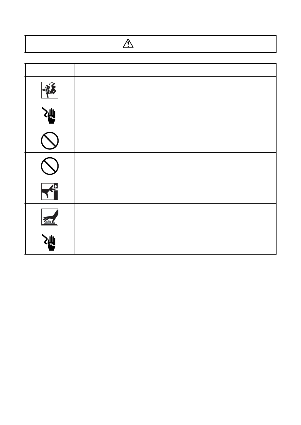
Basic cautions
Be careful not to let the patient touch this instrument. The patient's hand may be pinched by the
movable part.
Do not touch the focusing knob while in auto focus mode. You may be injured.
When operating the chinrest switch, be careful not to pinch the patient's hand. The patient may
be injured.
To avoid electric shock, turn off the power switch when replacing the lamp.
To avoid burns, allow lamp to cool before replacing.
To avoid injury caused by electric shock, do not open the cover. Ask your dealer for service.
To avoid electric shock, turn off the power switch and unplug the power cord and then replace
the lamp with a rated one.
Disposal
When disposing of TRC-NW300 parts, follow the local regulations for disposal and recycling.
ENVIRONMENTAL CONDITIONS FOR USE
Temperature : 10°C - 40°C
Humidity : 30% - 90% (without dew condensation)
Air pressure : 700hPa - 1060hPa
STORING PLACE, USAGE PERIOD OR OTHERS
1. Environmental conditions (without package)
*Temperature : 10°C - 40°C
Humidity : 10% - 95% (without dew condensation)
Air pressure : 700hPa - 1060hPa
* THIS INSTRUMENT DOES NOT MEET THE TEMPERATURE REQUIREMENTS OF
ISO 15004-1 FOR STORAGE. DO NOT STORE THIS INSTRUMENT IN CONDITIONS
WHERE THE TEMPERATURE MAY RISE ABOVE 40°C OR FALL BELOW 10°C.
2. When storing the instrument, ensure that the following conditions are met:
(1) The instrument must not be splashed with water.
(2) Store the instrument away from environments where air pressure, temperature, humid-
ity, ventilation, sunlight, dust, salty/sulfurous air, etc. could cause damage.
(3) Do not store or transport the instrument on a slanted or uneven surface or in an area
where it is subject to vibrations or instability.
(4) Do not store the instrument where chemicals are stored or gas is generated.
3. Normal life span of the instrument:
8 years from delivery providing regular maintenance is performed [TOPCON data]

3
ENVIRONMENTAL CONDITIONS FOR PACKAGING IN STORAGE
Temperature : -20°C - 50°C
Humidity : 10% - 95%
ENVIRONMENTAL CONDITIONS FOR PACKAGING IN TRANSPORTATION
Temperature : -40°C - 70°C
Humidity : 10% - 95%
CHECKPOINTS FOR MAINTENANCE
1. Periodically inspect the instrument and its parts.
2. Before using the instrument after a long period of inactivity, make sure that it operates
safely and normally.
3. Be careful not to stain the objective lens with fingerprints, dirt, etc., as this will affect picture
quality.
4. When the instrument is not in use, cap the objective lens and cover the instrument with the
dust cover.
5. If the objective lens is stained, clean it according to "Cleaning the objective lens" on page 78
of this manual.

4
DISPLAY FOR SAFE USE
To encourage safe and proper use and to prevent danger to the operator and others or potential
damage to properties, important messages are put on the instrument body and inserted in the
instruction manual.
We suggest that everyone understand the meaning of the following displays, icons and text before
reading the "SAFETY CAUTIONS" and observe all listed instructions.
DISPLAYS
ICONS
Display Meaning
WARNING Incorrect handling by ignoring this display may lead to an
impending danger of death or serious injury.
CAUTION Incorrect handling by ignoring this display may lead to personal
injury or physical damage.
•Injury refers to hurt, cuts, bruises, electric shock, etc. which does not require hospitaliza-
tion or extended medical treatment.
•Physical damage refers to extensive damage to the building, nearby equipment and/or
surrounding furniture.
Icon Meaning
Prohibition.
Specific content is expressed with words or a picture near the
icon.
Mandatory Action
Specific content is expressed with words or a picture near the
icon.
Caution
Specific content is expressed with words or a picture near the
icon.

5
SAFETY CAUTIONS
WARNINGS
Icon Prevention item Page
To avoid fire and electric shock in case of leakage, be sure to use
a grounded outlet. Do not connect to outlets that are not grounded. 23
To avoid electric shock, do not attempt disassembling, rebuilding
and/or repairs on your own. Ask your dealer for repairs. 61
Do not remove the covers from the main unit, chinrest unit or
power supply unit except for the lamp house cover. You may
receive an electric shock. 61
To avoid electric shock, unplug the power cord from the grounded
outlet before removing the fuse cover. Do not connect the power cord
to the grounded outlet with the fuse cover not correctly attached.
74
To avoid fire in the event of an instrument malfunction, use only
fuses that are fitted to the marked label at the side of the fuse
holder. 74
To avoid fire and electric shock, install the instrument in a dry
place free of water and other liquids. -----
To avoid fire and electric shock, do not put cups or other contain-
ers with liquids near the instrument. -----
To avoid electric shock, do not insert metal objects into any vents
and/or slots. -----
To avoid fire in the event of an instrument malfunction, immediately
turn OFF the power switch " " and unplug the cable if you see
smoke coming from the instrument, etc. Ask your dealer for ser-
vice.
-----

6
SAFETY CAUTIONS
CAUTIONS
Icon Prevention item Page
To prevent damage and injuries, install the instrument on a level
surface. 18, 69
To avoid electric shock, do not handle the plugs with wet fingers. 23
To avoid pain and discomfort to the patient and damage to the
patient’s eye, do not brighten the illumination lamp more than nec-
essary. 40
To avoid pain and discomfort to the patient and damage to the
patient's eye, do not brighten the photography light more than nec-
essary. 41
To avoid injury while moving the instrument, do not place your fin-
gers into the gap between the instrument body and the power sup-
ply unit. 43
To avoid burns, allow lamp to cool before touching. 71
To avoid electric shock, do not touch the xenon lamp immediately
after it flashes or burns out. 72

7
SAFETY CAUTIONS
CAUTIONS
Icon Prevention item Page
Before transporting this instrument, secure the fixing knob on the
bottom to prevent movement. 18
This instrument should be carried by two persons. Carrying by
one person may cause backache or injury. Holding at areas other
than the bottom may also cause injury, as well as falling, thereby
damaging the instrument.
18
To avoid electric shock, unplug the power cord from the outlet
before assembling.
Do not plug the power cord into the outlet before assembling the
instrument.
18
To avoid injury to the patient's face and hands, be sure to operate
the chinrest for height adjustment while observing the patient. 38
To avoid injury to the patient's eyes and nose while moving the
instrument body, keep a safe distance between the patient and the
objective lens. 43
To avoid electric shock, be sure to turn the power switch off and
unplug the power cord before replacing the lamp. 71, 72
Always place and transport the instrument on a suitable instru-
ment table. -----
This instrument has been tested (with 100/120/230V) and found to
comply with IEC60601-1-2: Ed.2.1: 2004.
This instrument radiates radio frequency energy within standard
and may affect other devices in the vicinity.
If you have discovered that turning on/off the instrument affects
other devices, we recommend you change its position, keep a
proper distance from other devices, or plug it into a different outlet.
Please consult your authorized dealer if you have any additional
questions.
-----

8
USAGE AND MAINTENANCE
USER MAINTENANCE
To ensure the safety and performance of the instrument, all maintenance work, unless speci-
fied in this manual, shall only be conducted by trained service engineers.
The following maintenance tasks may be done by the user.
For details, see the relevant part of this manual.
Replacing lamps:
The illumination lamp and xenon lamp may be replaced by the user. For details, see "Replac-
ing the illumination lamp" on page 71 and "Replacing the xenon lamp" on page 72.
Replacing fuses:
Fuses of the instrument body may be replaced by the user. For details, see "Changing the
fuse" on page 74.
Cleaning the objective lens:
The objective lens may be cleaned by the user. For details, see "Cleaning the objective lens"
on page 78.
ESCAPE CLAUSES
Usage:
•The TRC-NW300 NON-MYDRIATIC RETINAL CAMERA is an electric instrument for medi-
cal use. Use it accordingly.
•TOPCON shall not take any responsibility for damage due to fire, earthquakes, actions
by third persons and other accidents, or damage due to negligence and misuse by the
user and any use under unusual conditions.
•TOPCON shall not take any responsibility for damage derived from inability to properly
use this instrument, such as loss of business profit and suspension of business.
•TOPCON shall not take any responsibility for damage caused from using this instru-
ment in a manner other than that described in this Instruction Manual.
•Diagnoses made shall be the responsibility of pertaining doctors and TOPCON shall not
take any responsibility for the results of such diagnoses.

9
WARNING DISPLAYS AND POSITIONS
To ensure safety, this machine provides warning displays.
Use the instrument correctly by observing the display instructions. If any of the following dis-
play labels are missing, contact your TOPCON dealer at the address listed on the back cover.
300
CAUTION
Do not touch the focusing
knob while in auto focus
mode. You may be injured.
CAUTION
When operating the chinrest switch, be care-
ful not to pinch the patient's hand. The patient
may be injured.
CAUTION
yTo avoid electric shock, turn off the
power switch when replacing the lamp.
yTo avoid burns, do not replace the lamp
with a new one immediately after it goes
off because it is still very hot and can
cause burns.
WARNING
To avoid injury caused by electric shock,
do not open the cover. Ask your dealer for
service.
WARNING
To avoid electric shock, turn off the power
switch and unplug the power cord and then
replace the lamp with a rated one.
CAUTION
Be careful not to hit the patient's eyes or nose
with the instrument during operation.

10
CONTENTS
INTRODUCTION .................................................................................................................1
CAUTIONS FOR USE .........................................................................................................2
ENVIRONMENTAL CONDITIONS FOR USE .....................................................................2
STORING PLACE, USAGE PERIOD OR OTHERS ............................................................2
ENVIRONMENTAL CONDITIONS FOR PACKAGING IN STORAGE ................................3
ENVIRONMENTAL CONDITIONS FOR PACKAGING IN TRANSPORTATION .................3
CHECKPOINTS FOR MAINTENANCE ...............................................................................3
DISPLAY FOR SAFE USE ..................................................................................................4
SAFETY CAUTIONS ...........................................................................................................5
USAGE AND MAINTENANCE .............................................................................................8
ESCAPE CLAUSES .............................................................................................................8
WARNING DISPLAYS AND POSITIONS ............................................................................9
NOMENCLATURE
COMPONENT NAMES ......................................................................................................12
COMPOSITION OF PARTS THAT COME IN CONTACT WITH THE PATIENT ...............12
CONTROL PANEL COMPONENTS ..................................................................................13
COMPONENTS ON COLOR LCD MONITOR SCREEN ...................................................15
STANDARD ACCESSORIES ............................................................................................17
PREPARATIONS
ASSEMBLY PROCEDURE OF THE INSTRUMENT BODY ..............................................18
INSTALLATION/REMOVAL OF COMPACTFLASH CARD ...............................................20
CONNECTING THE USB MEMORY .................................................................................21
CONFIRMATION AFTER ASSEMBLY ..............................................................................22
CONNECTING THE POWER CORD ................................................................................23
CONNECTING THE EXTERNAL DEVICE ........................................................................24
MENU SETTING ................................................................................................................25
RESET FROM POWER SAVE STATE ..............................................................................36
BASIC OPERATIONS
FLOW OF OPERATION ....................................................................................................37
OTHER TYPES OF PHOTOGRAPHY ...............................................................................37
PREPARATION FOR PHOTOGRAPHY ............................................................................38
COLOR PHOTOGRAPHY (CENTER) ...............................................................................40
EXITING .............................................................................................................................48
OBJECTIVE OPERATIONS
PHOTOGRAPHY OF OTHERS EXCEPT "CENTER" .......................................................49
SMALL PUPIL PHOTOGRAPHY .......................................................................................50
ANTERIOR SEGMENT PHOTOGRAPHY .........................................................................53
IMAGE PLAYBACK MODE ................................................................................................55
BEFORE REQUESTING SERVICE
TROUBLESHOOTING .......................................................................................................59
SPECIFICATIONS & PERFORMANCE
SPECIFICATIONS .............................................................................................................63
ELECTROMAGNETIC COMPATIBILITY ...........................................................................64

11
ELECTRIC RATING ...........................................................................................................67
SYSTEM CLASSIFICATION ..............................................................................................67
DIMENSIONS AND WEIGHT ............................................................................................68
PURPOSE OF USE ...........................................................................................................68
OPERATION PRINCIPLE ..................................................................................................68
MAINTENANCE
DAILY CHECKUPS ............................................................................................................69
CLEANING .........................................................................................................................78
OPTIONAL ACCESSORIES
EXTERNAL FIXATION TARGET EF-2 ..............................................................................80
OTHER OPTIONAL ACCESSORY ....................................................................................80
REFERENCE MATERIAL
SHAPE OF PLUG ..............................................................................................................81
SYMBOL ............................................................................................................................81
USABLE AUTOMATIC INSTRUMENT TABLE ..................................................................81
RELATION BETWEEN SETTING OF ILLUMINATION/
FLASH LEVEL AND MAXIMUM RADIANCE ...................................................82
INFORMATION ABOUT THE OPTICAL RADIATION
HAZARD TO THE USER .............................................................................................83

12
NOMENCLATURE
NOMENCLATURE
COMPONENT NAMES
COMPOSITION OF PARTS THAT COME IN CONTACT WITH THE PATIENT
Forehead rest : Silicone rubber
Chinrest : Acrylonitrile butadiene styrene resin
Chinrest tissue pin : Polyamide resin
Diopter compensation
Focusing knob
IR filter selector
Control panel
Access lamlp
LED illuminator
Color LCD monitor
Image quality adjustment switch
Photography switch
Control lever
Base brake knob
Power lamp
Fixing knob (for carrying)
lens selector
Main unit
Power supply unit
Chinrest unit
Forehead rest
Canthus marker
Lamp house cover screw
Lamp house cover
Chinrest
Objective lens
Chinrest tissue pin
Base unit
Fuse holder
Power supply unit
Power switch
Image/data terminal
Input/output terminal
Connector

13
NOMENCLATURE
CONTROL PANEL COMPONENTS
Menu switch: P.25
Displays "MENU".
Split switch: P.46
Turns on/off the split line.
* (The function of the split switch can be changed by setting. For example, this switch can
be set in order to turn on/off the internal fixation target.)
Flash level switch: P.41
Adjusts the flash level according to the patient's eye condition.
Illumination level switch: P.40
Adjusts the illumination level according to the patient's eye condition.
Chinrest switch: P.39
Adjusts the chinrest up/down movement.
ID input switch: P.38
(Zoom switch)
Moves to the ID input screen.
(Magnifies the image by "2×" and "4×" during the image playback mode.)
Image playback switch: P.55
Reproduces the image stored in the set record media.
(This switch function is invalidated by the setting on the external recording device and the
instrument.)
Menu switch Split switch
Flash level switch
Illumination level
Chinrest switch
ID input switch Image playback switch
(-, reset, +)
switch (-, +)
(down, up)
Illumination diaphragm
(Upward cursor switch)
Fixation target selector
(Rightward cursor
Fixation target selector
(ENTER switch)
AUTO switch
(Downward cursor switch)
(Image deletion switch)
Fixation target selector
(Leftward cursor switch)
switch
switch
switch)
selector switch
switch
(PRINT switch)
(Zoom playback switch) Thumbnail switch
(Protect switch)

14
NOMENCLATURE
Illumination diaphragm selector switch: P.50
(Upward cursor switch): P.25, P.38
(Protect switch): P.58
Used in small pupil photography. IN/OUT of the illumination diaphragm for small pupil
(hereinafter, small pupil diaphragm) is done.
(You can move the selection cursor upward when entering the menu and ID.)
(You can protect images to prevent important images from being deleted.)
AUTO switch: P.46
(Downward cursor switch): P.25, P.38
(Image deletion switch): P.58
Turns ON/OFF the auto shoot/auto focus/auto small pupil functions. (ON/OFF of each func-
tion can be set by "MENU".)
(You can move the selection cursor downward when entering the menu and ID. Turns ON/
OFF to delete the reviewed photographic image.)
Fixation target selector switch: P.49
(Leftward cursor switch): P.38
Switches the position of the internal fixation target to guide the patient's eye to the fixation
point at the temporal/nasal side.
(You can move the selection cursor leftward when entering the menu and ID.)
Fixation target selector switch: P.49
(Rightward cursor switch): P.38
Switches the position of the internal fixation target to guide the patient's eye to the fixation
point at the temporal/nasal side.
(You can move the selection cursor rightward when entering the menu and ID.)
Fixation target selector switch: P.49
(ENTER switch): P.25, P.38
(PRINT switch): P. 58
Switches the position of the internal fixation target to guide the patient's eye to the fixation
point at the temporal/nasal side.
(You can decide the selected item in the menu. Turn ON this switch to print the reviewed
image.)
Thumbnail switch: P.55
Displays the photographed image in the thumbnail status.
* For details, contact your dealer or TOPCON (see the back cover).

15
NOMENCLATURE
COMPONENTS ON COLOR LCD MONITOR SCREEN
Monitor screen
* When the ( ) scale blinks in red, pull the base toward you (the operator) to the limit. For mov-
ing the instrument, refer to page 43.
The AUTO display shows the auto function that is ON. For setting the auto functions,
refer to "MENU SETTING" on page 25.
"F" is lit: The auto focus function is ON. (Set it to "OFF", and "F" is darkened.)
"S" is lit: The auto shoot function is ON. (Set it to "OFF", and "S" is darkened.)
"P" is lit: The auto small pupil function is ON. (Set it to "OFF", and "P" is dark-
ened.)
When the auto function, which has been set to "ON", is invalidated, a red
oblique line is displayed.
The left figure shows that the auto small pupil function is invalidated.
MENU screen
15
Patient ID
AUTO display
Xenon charging display
Flash level compensation
Small pupil diaphragm
Fixation target position
Right/left eye
Alignment bright spot
* ( ) scale
Split lines
Illumination level
Diopter compensation lens
USB memory recognition
External connection device
Printer recognition display
display
display
recognition display
The rest of image quantity in
CF CARD
Counter
AUTO
FSP
AUTO
FSP
MENU
ON
SHOOT
FLASH
MEMORY
SMALL PUPIL
OFF
FOCUS
EXPOSURE
FIXATION
FOCUS Icon
Item to be set Contents to be set

16
NOMENCLATURE
Preview screen (right after photographing)
Preview screen (in the image playback mode)
∗Displayed only when the flash level is compensated by the auto exposure function.
Photographic image
Patient ID
AUTO display
Xenon charging display
Flash level compensation
Small pupil diaphragm
Fixation target position
Right/left eye
Diopter compensation lens
Printer recognition display
display
Illumination level
Counter
012345678901234567890123-0001 ’08.10.20
100_0001
15
Patient ID
∗AUTO display
Flash level compensation
Fixation target position
Right/left eye
Printer recognition display
Protect display
Filename
Date
∗Auto exposure compensation
The rest of image quantity in
CF CARD

17
NOMENCLATURE
STANDARD ACCESSORIES
Upon unpacking, make sure that all the following standard accessories are included. Numbers
in ( ) are the quantities.
Power cord (1) Chinrest tissue pin (2)
Chinrest tissue paper (1) Fuse (spare) (2)
Instruction manual (1) Dust cover (1)
Spare parts case (1) Rail cover (2)
Screw (4) USB cable (1)
INSTRUCTION MANUAL
NON-MYDRIATIC RETINAL CAMERA
TRC-NW300

18
PREPARATIONS
PREPARATIONS
ASSEMBLY PROCEDURE OF THE INSTRUMENT BODY
1Take out the instrument body from the cardboard box and put it on the table.
Before transporting, make sure that the back-and-forth and right-and-left movement of the
base stops because of the fixing knob. If the base moves, turn the fixing knob to stop it.
When carrying the instrument body, firmly hold it at the following specified positions.
2Loosen the fixing knob.
CAUTION Before transporting this instrument, secure the fixing knob on the bot-
tom to prevent movement.
CAUTION
This instrument should be carried by two persons. Carrying by one
person may cause backache or injury. Holding at areas other than the
bottom may also cause injury, as well as falling, thereby damaging the
instrument.
CAUTION To prevent damage and injuries, install the instrument on a level sur-
face.
CAUTION
To avoid electric shock, unplug the power cord from the outlet before
assembling.
Do not plug the power cord into the outlet before assembling the
instrument.
NOTE Since the upper part and lower part of the instrument body are con-
nected to each other with the power cable, take them out together so
they do not separate from each other.
NOTE Always place the instrument in the center of the instrument table.
Holding positions Fixing knob Holding the instrument body
Table of contents
Other Topcon Laboratory Equipment manuals
Popular Laboratory Equipment manuals by other brands

TSI Instruments
TSI Instruments BIOTRAK 9510-BD-P quick start guide

Cerillo
Cerillo stratus quick start guide

Julabo
Julabo F12-ED operating manual

Okolab
Okolab H301-PI-736-ZR1S user manual

Aqua Ultraviolet
Aqua Ultraviolet Viper SL Series installation manual

Thermo Scientific
Thermo Scientific Sorvall RC6 Plus Operation instructions

Agilent Technologies
Agilent Technologies 5975T LTM GC/MSD Troubleshooting and maintenance guide

Metrohm
Metrohm 804 Ti Stand manual

THORLABS
THORLABS OCTP Series user manual

Drucker Diagnostics
Drucker Diagnostics 642VFD Service manual

MABTECH
MABTECH ASTOR 2 operating instructions

illumina
illumina NextSeq 550Dx Instrument Reference Guide