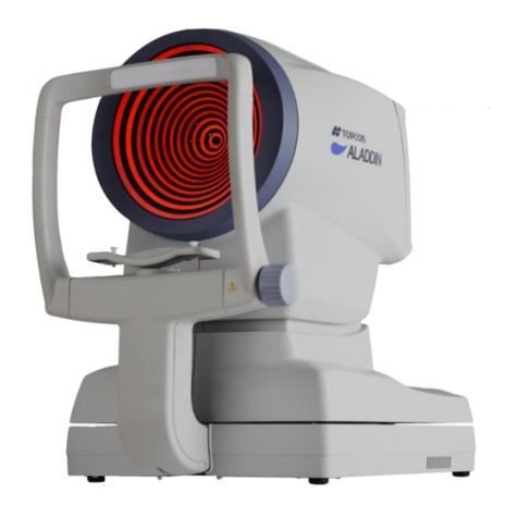
Topcon Compu-Vision CV-5000 Operating instructions

REPAIR MANUAL
ISSUED ...............APR. 2007
REVISED.............
COMPU-VISION
CV-5000
TOPCON CORPORATION
R-CV5000-0-0704-01

CONTENTS
Page
1. OUTLINE.................................................................................................................................... 1
1-1 Features of Product.............................................................................................................. 1
1-2 Operation Principle............................................................................................................... 1
1-3 Specifications of Product...................................................................................................... 1
1-4 Target Users of This Repair Manual ..................................................................................... 2
1-5 How to Use This Repair Manual........................................................................................... 3
1-6 Cautions............................................................................................................................... 4
2. PRODUCT OUTLINE ................................................................................................................. 5
2-1 Nomenclature....................................................................................................................... 5
2-2 Optical Arrangement and Names ......................................................................................... 6
2-3 Electrical Wiring Diagram..................................................................................................... 7
3. REPAIR ...................................................................................................................................... 8
3-1 Disassembly and Assembly Procedures............................................................................... 8
3-2 Names of PCB................................................................................................................... 15
3-3 Specifications of Switches.................................................................................................. 18
3-4 Names of Motors and Sensors........................................................................................... 20
3-5 Trouble Shooting................................................................................................................ 22
3-6 Assembly and Adjustment Procedures............................................................................... 43
3-7 Version up of software........................................................................................................ 48
3-8 Replacement of the PCB for the near-point illumination LED.............................................. 53
4. TOOLS..................................................................................................................................... 55
4-1 Special Tools...................................................................................................................... 55
4-2 General Tools..................................................................................................................... 56
R-CV5000-0-0704-01

−1 −
1. OUTLINE
1-1 Features of Product
This instrument is a refractor and the lenses having a variety of power are built in it to measure the refraction
of eyes. This instrument is used to measure the correction quantity of refraction and to perform the
binocular function test according to the answers of the patient. The lenses built in this instrument are
changed by the accessory controller or the commercial personal computer to which the special software is
installed.
1-2 Operation Principle
On a disk built in the instrument, the lenses with a variety of power are arranged. By turning the disk, the
lenses are changed to each other. There are two or more disks in the instrument. So, measurement of
different types can be carried out by combining the disks.
1-3 Specifications of Product
1-3-1 Specifications by items
•Spherical power:
Measuring range +27.00 ~ -27.00D
Measuring step 0.25D/3.00D
•Astigmatic power:
Measuring range +8.00 ~ -8.00D
Measuring step 0.25D/1.00D
•Cylinder axis:
Measuring range 0 ~ 180°
Measuring step 1°/5°/15°
•Prism power:
Measuring range 0 ~ 20∆(all directions)
Measuring step 0.1∆/0.5∆/1.0∆
•Pupillary distance:
Setting range 48 ~ 80mm
Setting step 0.5mm/1mm
•Cross cylinder:
Jackson Cross ±0.25D/±0.50D
Auto Cross ±0.25D
•Test lens (Auxiliary lens):
Red-Green filter
Polarized filter (45°/135°)
Prism (6∆/10∆)
Red Maddox (horizontal/vertical)
Lens for retinoscopy (+1.5D/+2.0D)
Cross cylinder for measuring presbyopia (±0.5D)
Occluding plate
R-CV5000-0-0704-01

−2 −
Pinhole
Cross hairs glass
•Standard wearing distance: 12mm, 13.75mm, 16mm, 18mm, 20mm
•Convergence: Near-point distance 40/67cm (Minimum pupillary distance to
enable convergence at the near point 40cm: 53mm)
•Forehead rest adjustment range: 15mm
1-3-2 Other specifications
•Horizontal adjustment: 4° or more in right and left
•Tilt for near point: 30°
•Near-point illumination: White LED
•Input of objective data/CL data: Input the measurement data of RM or CL into CV.
•Remote control of ACP-8/MC-3/PC-2: Remote control ofACP-8, MC-3 or PC-2 is possible.
•Electric rating:
For Japan Power supply voltage: AC100V, Frequency: 50-60Hz
For export Power supply voltage: AC100-240V, Frequency: 50-60Hz
Power supply input: 90VA
•Dimensions and weight:
Dimensions: 294 ~ 328mm (W) × 115mm (D) × 261mm (H)
Weight: 4kg
Types of protection against electric shocks: Class I equipment
Degree of protection against electric shocks: Type B applied part
1-4 Target Users of This Repair Manual
Only the service engineer having experience in assembling and adjusting ophthalmic instruments must repair
this instrument. For others, it is recommended to take the repair training lessons of TOPCON
CORPORATION.
R-CV5000-0-0704-01

−3 −
1-5 How to Use This Repair Manual
When performing the inspection or when inspecting, adjusting or repairing the instrument for its trouble,
follow the flow chart shown below.
R-CV5000-0-0704-01

−4 −
1-6 Cautions
(1) Before replacing a connector or PCB, turn off the power.
(2) When a PCB malfunctions, replace it as a PCB unit.
Replaceable PCB Part No.
1. MAIN PCB 43221 51000
2. L PCB 43221 52000
3. R PCB 43221 53000
When you replace the MAIN PCB, remove E²PROM from the old PCB and install it to the new PCB.
(3) When the screw lock is used for a screw, dissolve the screw lock with Isoamyl acetate and then remove
the screw.
(4) Use the screw lock (THREE-BOND 1401B) for screws.
(5) When assembling, install the parts in the reversed procedure of disassembly.
(6) Refer to “Assembly andAdjustment Procedures” for adjustment in repair and assembly.
R-CV5000-0-0704-01

−5 −
2. PRODUCT OUTLINE
2-1 Nomenclature
No.
Name Function
1
Examination window The patient’s eyes are observed through this window, and the display
lenses are set here.
2
Corneal aligning window The position of the patient’s cornea is seen through this window.
3
Forehead rest knob Adjusts the forehead in the back-and-forth direction.
4
Leveling knob Levels the instrument.
5
Near-point rod holder The near-point rod is inserted and attached here.
6
Near-point rod clamp screw Fixes the near-point rod.
7
Forehead rest The patient’s forehead rests here.
8
Cornea alignment scale Measures the cornea vertex position.
9
Power connection cord This cord connects the instrument to the power supply.
10
Level Indicates the standard position for the level adjustment.
11
Cornea illumination Brightens the anterior eye segment to check the PD easily even during
optometry in a dark room.
12
Chart illumination LED Illuminates the near-point chart.
13
Tilt fixing lever for near point Adjust the tilt for near-point test.
R-CV5000-0-0704-01

−6 −
2-2 Optical Arrangement and Names
No.
Name Function
1
Cover glass at the patient side Prevents eyelashes, dust, etc. from contacting the lens.
2
Spherical lens No. 3 This is a group of high power spherical lenses.
3
Spherical lens No. 2 This is a group 2 of low power spherical lenses.
4
Spherical lens No. 1 This is a group 1 of low power spherical lenses.
5
Cylindrical lens No. 2 This is a group of high power cylindrical lenses.
6
Cylindrical lens No. 1 This is a group of low power cylindrical lenses.
7
Auxiliary lens group This is a group of lenses for correcting errors when combining a high
power spherical lens with a cylindrical lens.
8
Prism: CC lens group 2 It is possible to combine the prism lenses of 20∆~ 0 ~ 20∆.
: Cross cylinder lens of ±0.25D/0.50D
9
Prism: CC lens group 1 It is possible to combine the prism lenses of 20∆~ 0 ~ 20∆.
: Cross cylinder lens of ±0.25D/0.50D
10
Cover glass at the inspector side Prevents dust.
11
Cornea alignment cover glass
(at the patient side) Prevents dust.
12
Cornea alignment scale Shows the cornea position.
13
Cornea alignment mirror Used to see the cornea position from the front of the instrument.
14
Cornea alignment cover glass
(at the inspector side) Prevents dust.
Patient’s eye
R-CV5000-0-0704-01

− 7 −
2-3 Electrical Wiring Diagram
R-CV5000-0-0704-01

−8 −
3. REPAIR
3-1 Disassembly and Assembly Procedures
3-1-1 Removal of PD cover
Illustration
Procedure
1. Remove the screw covers and the two screws CR3 × 6SCr
1
. Then, remove the connector
cover.
2. Remove the screw covers and the two screws CR3 × 6SCr
2
. Then, remove the PD cover
at inspector side.
3. Remove the two screws CR3 × 6SCr
3
and then remove the near-point rod holder.
4. Remove the screw 6SU3 × 3SCr
4
and then remove the forehead rest knob.
5. Remove the tilt fixing lever.
6. Remove the two screws CR3 × 6SCr
5
and then remove the PD cover at patient side.
Note: When installing the PD connector cover, put the cable into the cover’s groove.
Tilt fixing lever
Near
-
point rod holder
PD cover at patient side
Forehead rest knob
PD connector cover
Screw cover
PD cover at inspector side
R-CV5000-0-0704-01

−9 −
3-1-2 Removal of lens cover
Illustration
Procedure
1. Remove the face shield.
2. Remove the two screws CR3 × 3SCr
1
and then remove the lens cover at patient side.
* This cover has a claw. Remove it as pushing the arrow section of the lens cover at
inspector side.
3. Remove the four screws CR3 × 6SCr
2
and then remove the lens cover at inspector side.
4. Remove the cover at the right eye side in the same way as the cover at the left eye side.
Lens cover at patient side
Face sh
ield
Lens cover at inspector side
R-CV5000-0-0704-01

−10 −
3-1-3 Removal of lens PCB
Illustration
Procedure
1. Remove the tape wires and all the connectors from the L PCB.
2. Remove the two screws CR3 × 4Ni
1
and one screw CR2.5 × 4Ni
2
. Then, remove the
L PCB.
3. Remove the R PCB in the same way as the L PCB.
Note: When installing, attach the insulation sheet.
R PCB
L PCB
R-CV5000-0-0704-01

−11 −
3-1-4 Removal of MAIN PCB
Illustration
Procedure
1. Remove the power box relay cable.
2. Remove the tape wires and all the connectors from the MAIN PCB.
3. Remove the five screws CR3 × 4Ni
1
and then remove the MAIN PCB.
Note: When installing, attach the insulation sheet.
MAIN PCB
Power box relay cable
R-CV5000-0-0704-01

−12 −
3-1-5 Removal of spherical unit
Illustration
Procedure
1. Remove the binding band of the spherical unit. (Zero detection sensor and cornea unit)
2. Remove the wires, which are bound by the harness clip and coating clip.
3. Remove the three screws CR3 × 5S3BZn
1
.
4. Remove the spherical unit L.
5. Remove the spherical unit R in the same way as the spherical unit L.
Spherical unit R
Spherical unit L
R-CV5000-0-0704-01

−13 −
3-1-6 Removal of lens unit
Illustration
Procedure
1. Remove the tape wires at the lens side.
2. Remove the four screws W sems 6S4 × 6S3BZn
1
.
3. Remove the four screws W sems 6S4 × 6S3BZn
2
and then remove the lens units L and R.
Lens unit L
Lens unit R
R-CV5000-0-0704-01

−14 −
3-1-7 Removal of CV arm
Illustration
Procedure
1. Remove the screw CQS2 × 3Cr
1
and then remove the arm cover.
2. Remove the screw 6S6 × 10SCr
2
and then remove the plate spring.
3. Remove the screw 6SU4 × 4S3BZn
3
and the screw 6SU4 × 10S3BZn
4
.
4. Remove the three screws 6S4 × 12SCr
5
and separate the disk from the arm mounting
shaft. Then, remove the CV arm.
Note: When installing the CV arm, the rotation force of the CV instrument is adjusted by the
tightening force of the screw
2
. Adjust the force properly.
Plate spring
Arm cover
Disk
CV arm
Arm mounting shaft
R-CV5000-0-0704-01

−15 −
3-2 Names of PCB
3-2-1 MAIN PCB
J100 : The PD sensor is connected.
J101 : The convergence sensor is connected.
J105 : The power box relay cable is connected.
J106 : The convergence motor is connected.
J107 : The PD motor is connected.
J109 : The near-point chart LED for left eye is connected.
J110 : The near-point chart LED for right eye is connected.
J112 : The tool PCB is connected (when correcting).
J151 : The left eye flexible cable is connected.
J152 : The right eye flexible cable is connected.
SW1 : Zero detection switch
SW2 : DIP switch for correction
IC1 : CPU
IC11 : EEPROM
R-CV5000-0-0704-01

−16 −
3-2-2 L PCB
J301 : The spherical motor No. 1 (S1) is connected.
J302 : The spherical motor No. 2 (S2) is connected.
J303 : The spherical motor No. 3 (S3) is connected.
J304 : The cylindrical motor No. 1 (C1) is connected.
J305 : The cylindrical motor No. 2 (C2) is connected.
J306 : The auxiliary lens motor (AX) is connected.
J307 : The rotary prism motor (RP) is connected.
J308 : The RPCC1 motor (RP1) is connected.
J309 : The RPCC2 motor (RP2) is connected.
J310 : The cylindrical axis motor (CA) is connected.
J311 : The spherical lens zero detection sensor is connected.
J312 : The cylindrical lens zero detection sensor is connected.
J313 : The RPCC1 zero detection sensor is connected.
J314 : The RPCC2 zero detection sensor is connected.
J315 : The cylindrical axis zero detection sensor is connected.
J316 : The cornea illumination LED is connected.
J350 : The left eye flexible cable is connected.
R-CV5000-0-0704-01

−17 −
3-2-3 R PCB
J201 : The spherical motor No. 1 (S1) is connected.
J202 : The spherical motor No. 2 (S2) is connected.
J203 : The spherical motor No. 3 (S3) is connected.
J204 : The cylindrical motor No. 1 (C1) is connected.
J205 : The cylindrical motor No. 2 (C2) is connected.
J206 : The auxiliary lens motor (AX) is connected.
J207 : The rotary prism motor (RP) is connected.
J208 : The RPCC1 motor (RP1) is connected.
J209 : The RPCC2 motor (RP2) is connected.
J210 : The cylindrical axis motor (CA) is connected.
J211 : The spherical lens zero detection sensor is connected.
J212 : The cylindrical lens zero detection sensor is connected.
J213 : The RPCC1 zero detection sensor is connected.
J214 : The RPCC2 zero detection sensor is connected.
J215 : The cylindrical axis zero detection sensor is connected.
J216 : The cornea illumination LED is connected.
J250 : The left eye flexible cable is connected.
R-CV5000-0-0704-01

−18 −
3-3 Specifications of Switches
3-3-1 MAIN PCB·SW2
It is necessary to set this DIP SW when correcting the zero detection of each lens.
1
When clearing all the data of EEPROM
Set No. 7 and No. 8 to “ON”. (Turn on the power, and the data are cleared.)
2
When clearing part of the EEPROM data (concerned with axis)
Set No. 8 to “ON”. (Turn on the power, and the data are cleared and then zero detection is done.)
3
When correcting the zero detection of each motor
Set the DIP SW of the lens to be corrected to “ON” to perform correction.
Motor name DIP SW
• PD motor tool mode SW1 is ON.
PD • Convergence motor tool mode SW2 is ON.
• S1 motor tool mode SW3 is ON.
• S2 motor tool mode SW5 is ON.
• S3 motor tool mode SW1 and SW2 are ON.
• C1 motor tool mode SW1 and SW4 are ON.
• C2 motor tool mode SW1 and SW6 are ON.
• AX motor tool mode SW2 and SW4 are ON.
• RPCC motor tool mode SW2 and SW6 are ON.
• RP1 motor tool mode SW3 and SW5 are ON.
• RP2 motor tool mode SW4 and SW5 are ON.
Right
• CA motor tool mode SW5 and SW6 are ON.
• S1 motor tool mode SW4 is ON.
• S2 motor tool mode SW6 is ON.
• S3 motor tool mode SW1 and SW3 are ON.
• C1 motor tool mode SW1 and SW5 are ON.
• C2 motor tool mode SW2 and SW3 are ON.
• AX motor tool mode SW2 and SW5 are ON.
• RPCC motor tool mode SW3 and SW4 are ON.
• RP1 motor tool mode SW3 and SW6 are ON.
• RP2 motor tool mode SW4 and SW6 are ON.
Left
• CA motor tool mode SW1, SW2 and SW3 are ON.
R-CV5000-0-0704-01
Other manuals for Compu-Vision CV-5000
2
Table of contents
Other Topcon Laboratory Equipment manuals
Popular Laboratory Equipment manuals by other brands

Scilogex
Scilogex SCI100-Pro user manual

Hach
Hach PHC108 user manual

Thermo Scientific
Thermo Scientific iCAP 7000 Series manual

Endress+Hauser
Endress+Hauser Liquistation CSF48 operating instructions

MCCORMICK
MCCORMICK BACTI-CINERATOR IV operating manual

Fowler
Fowler Xtra-Value Series operating instructions

Air Science
Air Science Purair FLOW-24 User's operation manual

Biosan
Biosan RCP-24 User instructions

VERDER
VERDER Carbolite Gero HT 5/350 Installation, operation and maintenance instructions

Oxford Instruments
Oxford Instruments Andor Kymera 193i quick start guide

NuAire
NuAire 13 Series Operation and maintenance manual

Thomas
Thomas 1137 user guide