Gerhardt Vapodest 45s User manual

Vapodest 45s
Programmable rapid distillation system
with external titration
Vap 45s
01. December 2008_D
Please read this instruction manual with care before you start operating
the system!
Please observe the safety instructions of this manual marked with
Warnung vor
einer Gefahrenstelle
in
order to avoid any dangerous handling!
Warnung vor
einer Gefahrenstelle
Instruction Manual

2Vapodest 45s
Content
1 Important notes ..........................................................4
1.1 How to use this instruction manual................................................................ 4
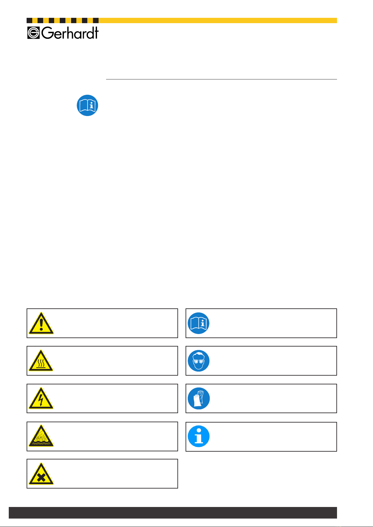
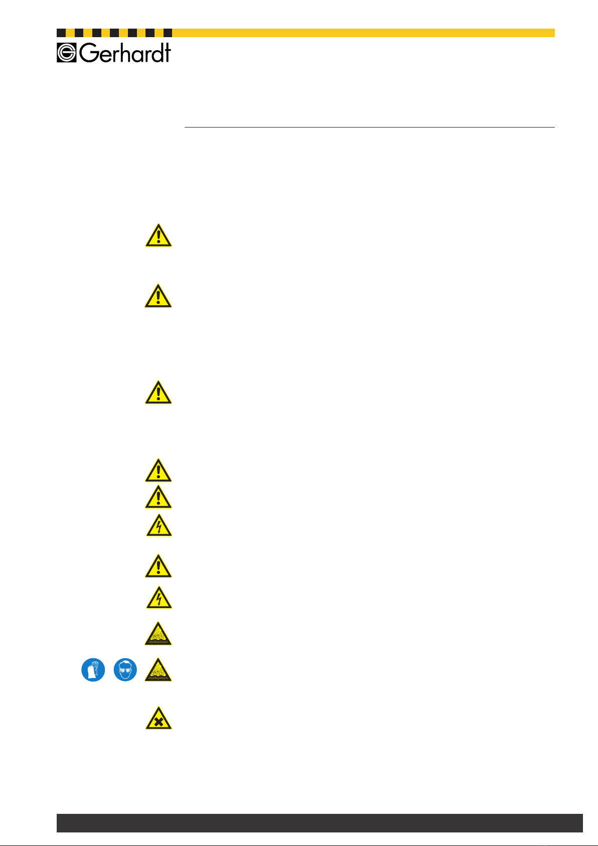
1.2 Explanation of symbols.................................................................................. 4
2 Safety...........................................................................5
2.1 Operation as directed .................................................................................... 5
2.2 Safety instructions ......................................................................................... 5
2.3. Work bench / Authorized user ...................................................................... 6
2.4. Danger spots at the instrument .................................................................... 6
3 Technial description...................................................7
3.1. Warranty conditions...................................................................................... 7
3.2. Technical data............................................................................................... 7
4 Assembly and Installation .........................................8
4.1. Check for transport damage......................................................................... 8
4.2. Unpack apparatus and set up....................................................................... 8
4.3. Package list .................................................................................................. 9
4.4 Front view Vapodest 45s - Version with titration ......................................... 10
4.4.1. Description of front view with titrator........................................................ 11
4.5 Front viewVapodest 45s without titration..................................................... 12
4.5.1. Description to front view without titration................................................. 13
4.6 Rear view Vapodest upper part ................................................................... 14
4.6.1. Description of rear view upper part ......................................................... 15
4.7. Tubing connections..................................................................................... 16
4.8. Mains connection Vapodest........................................................................ 17
4.9. Connection of titrator and electrode ........................................................... 18
4.9.1. Connection of the external titrator ........................................................... 19
4.9.2. Connection of the electrode..................................................................... 19
5 Turn on apparatus and operation ...........................20
5.1. Turn on apparatus ...................................................................................... 20
5.2. Control panel Vapodest .............................................................................. 21
5.3. Main menus Vapodest ................................................................................ 22
6 System settings........................................................23
6.1. Select language.......................................................................................... 23
6.2. Setting contrast........................................................................................... 24
6.3. Reagents .................................................................................................... 25
6.3.1. Set level sensor for tank.......................................................................... 25
6.3.2. Calibrate dosing pumps........................................................................... 25
6.4. Service (Statistic)........................................................................................ 27
6.5. Titration....................................................................................................... 28
6.5.1. Settings of the titrator .............................................................................. 29
7 Create a method (Programming).............................30
7.1. Dene a new method.................................................................................. 30
8 Execution of method................................................34
8.1. Prior to the analysis.................................................................................... 34
8.2. Distilling a sample without external titrator ................................................. 34
8.3. Distilling a sample with external titrator ...................................................... 36
8.4. Interrupt distillation .................................................................................... 38

3
Vapodest 45s
Content
9 Trouble shooting ......................................................39
9.1. Error messages .......................................................................................... 39
9.2. Breakdown of operation.............................................................................. 40
9.3. Results too high.......................................................................................... 41
9.4. Results too low or no results ...................................................................... 41
10 Rework instruction.................................................42
10.1. Upgrade the Vap 45s to be operated with external titrator ....................... 42
11 Maintenance............................................................43
11.1. Cleaning and regularly check ................................................................... 43
11.1.1. Cleaning general.................................................................................... 43
11.1.2. Cleaning program .................................................................................. 43
11.1.3. Check the tight tting of the tubes ......................................................... 43
11.2 Tubing diagram Vap 45 s (with open rear wall).......................................... 44
11.2.1. Description of the tubing diagram ........................................................ 45
11.3. Spare parts .............................................................................................. 46
11.4. Accessories............................................................................................... 47
12 Decommissio and disposal ...................................49
12.1. Decommission .......................................................................................... 49
12.2. Contact service ........................................................................................ 49
12.3. Disposal.................................................................................................... 50
12.3.1. Information for the Disposal of Electric and Electronic Instruments within
the European Union..................................................................................... 50
12.3.2. Ban on Materials according to ROHS Regulation 2002/95/EG ............. 50
12.3.3. Transfer ................................................................................................. 50

4Vapodest 45s
1 Important notes
1.1 How to use this instruction manual
Please make sure that the persons working with the Vapodest have read and
understood this manual in order to observe all the instructions.
This instruction manual must be accessible to all users at any time and is a part
of the Vapodest system!
The instrument will be called "Vapodest 45s" in the entire document.
This instruction manual only explains the technical details necessary for the ope-
ration of the instrument but is NOT a complete technical description.
The security advises given in this manual have to be observed under all circum-
stances! The symbols at the border of the text emphasize the dangers cited in
the text.
Symbols at the instrument warn of possible dangers and will refer you to this
manual!
The copy right of this manual remains with C.Gerhardt GmbH & Co. KG
Reproduction and copying are only allowed with the permission of C.Gerhardt
GmbH & Co. KG
1.2 Explanation of symbols
Warnung vor gefährlicher,
elektrischer Spannung
Warnung vor
einer Gefahrenstelle
Attention!
Advance notice of danger spots, carefully
read instruction manual!
Attention!
Hot surface!
Attention!
Mains voltage!
Attention!
Beware of hot liquids and vapours!
Attention!
Advance notice of substances which might
be a health risk or cause irritation!
Attention!
Read instruction manual!
Attention!
Use eye protection!
Attention!
Use protective gloves!
Notice!
Important information!

5
Vapodest 45s
2.1 Operation as directed
With the Vapodest 45s you have purchased an automatic distillation system for the
steam distillation e.g. of Kjeldahl digestions and associated distillations. Automa-
tic addition of H2O, NaOH and H3BO3as well as removal of the sample remains
after distillation by suction. The distillation system is prepared to work with an
external titrator.
Make sure to use the instrument according to our instructions, especially:
- all instructions of this manual
- the regulations in place in the country the instrument is used
All other usage is not recommended!
C. Gerhardt GmbH & Co. KG is not liable for any damages caused due to non
recommended usage
- no modications are allowed for safety reasons
- repairs of electric, electronic or mechanical components may only be done by
authorized personnel!
2.2 Safety instructions
The Vapodest 45s corresponds to the technical standard used at this date and
observes the safety rules and regulations in place.
It is understood that the user has to observe
- the accident prevention regulations in place
- the general accident prevention regulations
- EU-regulations or other country specic instructions
Indicating label and danger symbols must not be taken off!
Alle engineered safeguards must not be taken out of operation!
Make sure that no liquid gets into contact with cable connections or the interior of
the electrical parts of the unit!
- Danger of electric shock!
In case of an emergency disconnect from mains immediately!
Always pull the mains plug before opening!
- Danger of electric shock!
Prior to each start, make sure that the protection door is closed tightly.
Danger of burns and splashing liquids!
Make sure to wear protective gloves when taking the digestion tubes out and wear
protective glasses as well.
The digestion tubes are very hot and there is the danger of burns!
Attention when handling chemicals! Please observe the manufactures safety
instructions (see label) and your national safety regulations!
2 Safety
Warnung vor gefährlicher,
elektrischer Spannung
Warnung vor gefährlicher,
elektrischer Spannung
Warnung vor
einer Gefahrenstelle
Warnung vor
einer Gefahrenstelle
Warnung vor
einer Gefahrenstelle
Warnung vor
einer Gefahrenstelle
Warnung vor
einer Gefahrenstelle
Warnung vor
einer Gefahrenstelle

6Vapodest 45s
2 Safety
2.3. Work bench / Authorized user
The Vapodest 45s must not be run in damp or hazardous location. The maxi-
mum humidity allowed is 80 %, the maximum room temperature must not ex-
ceed 35 °C!
The equipment must not be exposed to aggressive vapors of acids, alkalis, or
solvents.
The Vapodest 45s has to be placed on a horizontal and stable footprint.
The Vapodest 45s may only be operated by trained staff or specially trained per-
sons.
The user has to:
- read, comprehend, and observe the operation manual
- wear suitable clothes for laboratory work
- deny access to any unauthorized personnel
Warnung vor
einer Gefahrenstelle
Warnung vor
einer Gefahrenstelle
Warnung vor
einer Gefahrenstelle
2.4. Danger spots at the instrument
- Attention, danger of burns on the surface of the digestion tubes!
- Attention, danger of splashing hot or caustic liquids at the tubing connections
at the back of the instrument!
- Attention, danger of burns when taking out the hot glass container!
Use gloves when removing the glass digestion tubes!
Warnung vor
einer Gefahrenstelle

7
Vapodest 45s
3.1. Warranty conditions
Vapodest 45s is designed and fabricated following the high quality guidelines of
DIN EN ISO 9001.
On the basis of the C. Gerhardt conditions of warranty, our products are guaranteed
for 12 months as long as the equipment is used according to the instructions in
this manual. Also ll in the "Report for the installation and initial operation" and
return it to C. Gerhardt.
Please note that the following parts are excluded from warranty.
- Digestion tube, Order-no.: 1002178
- Vitone cone, Order-no.: 12-0351
3.2. Technical data
Nominal voltage: 230 V AC, 50 Hz or 115 V 60 Hz or 230 V 60 Hz
Nominal wattage: 1600 W
Cooling water consumption:
about 5 liters per distillation minute
Cooling water pressure:
min. 0,5 bar, max. 6 bar
Pump capacity (read chapter 6.3.2. Calibration dosing pumps)
-
Diaphragm pump
about 15 ml/s with water
about 10 ml/s with NaOH
-
Peristaltic pump
about 10 ml/s with water
Storage tanks: any size, recommended:
Set of storage tanks KAN 40
Display: LED with illumination
Programs: 20
Dimensions: 440 x 690 x 340 mm (W x H x D)
Weight: 29 kg
Interfaces:
- Vapodest 2 x RS 485 interface: Connection for GerBus®
1 x RS 232 interface: Connection for titrator
1 x 5-pin connector for level sensor storage tanks
3 Technial description

8Vapodest 45s
4.1. Check for transport damage
Before assembling the apparatus please check if the content of the box is com-
plete and intact!
In case of any damage, please notify your carrier (post, rail, road) as well as
your supplier!
4.2. Unpack apparatus and set up
The VAPODEST must not be run in damp or hazardous location. The maximum
humidity allowed is 80 %, the maximum room temperature must not exceed 40 °C!
There should be sufcient space for the set of tanks below the work bench..
Make sure, however, that those tanks are not higher than the Vapodest!
You need a connection (cold water pipe) with 1/2 inch thread to connect it to the
water supply.
Make sure to take a faucet, which can be connected to the inlet tubing permanent-
ly. The water pressure must be at least 0,5 bar in order to activate the integrated
pressure detector.
Please observe the local water and waste regulations and those of your public
water supply company! Please note that the length of the inlet and outlet tubing
is restricted to 2 metres.
The VAPODEST 45s distillation system comes fully pre-assembled. Please unpack
the equipment with care !
1. Place the equipment on a stable work bench.
2. Unpack accessories
The exact contents of the delivery can be checked by the following list.
4 Assembly and Installation
Warnung vor
einer Gefahrenstelle

9
Vapodest 45s
4.3. Package list
1 x Distillation system Vapodest 45s, complete mounted
1 x Water inlet tube 10/17 mm with connections of 1/2 inch and 3/4 inch, 2m
Item-No. 1000394
1 x Verprene-tube 8/12, 2 m, Item No. 1000499
3 x PVC-tube 4/7, 2 m, Item-No. 1000500
3 x PVC-tube 8/12, 2 m, Item-No. 1000047
3 x PVC-pipe 6 x 1, 400 mm, Item-No. 1000566
1 x PVC-pipe 10 x 1, 400 mm, Item-No. 1000567
1 x Mains cable, Item-No. 10-0048
1 x Kjeldatherm-digestion tube, 250 ml, Item-No. 12-0301
1 x Instruction manual
1 x Test report
1 x Installation report
Optional:
1 x Titrator Titro Line easy, Item-No. 12-0054
1 x pH-Electrode with screw plug connection, Item-No. 12-0355
1 x Electrode cable DIN Vap 45, Item-No. 1002170
1 x Buffer solution pH 4, 250 ml, Item-No. 1000176
1 x Buffer solution pH 7, 250 ml, Item-No. 1000177
1 x KCL-Electrolyte solution, 250 ml, Item-No. 1000178
4 Assembly and Installation

10 Vapodest 45s
4 Assembly and Installation
4.4 Front view Vapodest 45s - Version with titration
4
5
1
6
7
8
9 10 11
12
13
14
15
2
3
16
18
20
17
24
21
22
23
19

11
Vapodest 45s
4 Assembly and Installation
4.4.1. Description of front view with titrator
1 Drip tray, Item-No. 1000399
Condensate which might drip is collected in the drip tray.
2 Quick clamping device with wedge, Item-No. 1000537
Press down the quickclamping device in order to insert digestion tube.
3 Kjeldatherm-digestion tube, Item-No. 12-0301
Special glass with cut, 250 ml
Also applicable, ask with enlarged neck 250/500/750 ml or KDD 400/800 ml.
4 PTFE-inlet tubing steam, Item-No. 1002178
Steam, water for dilution, and the suction of the sample residues passes through
here. Please check regularely that the opening of the PTFE-tube is not blocked
by crystallisation.
5 Viton cone, Item-No. 12-0351
Macro for 250 ml tubes or micro for 100 ml tubes
6 Screw cap GL18, Item-No. 1004321
with silicone/PTFE seal
7 PTFE-inlet tubing, NaOH, Item-No. 1003401
Sodium hydroxide solution enters here.
8 Distribution head glass, Item-No. 12-0363
Distribution head prevents that any sample residue gets into the receiver.
9 Screw cap GL32, Item-No. 1004322
with silicone/PTFE seal
10 Distillation condenser, Item-No. 1000058
Combined ball- and coil condenser with high cooling power.
11 Screw cap GL 14, Item-No. 1004320
with plastic screw connection
12 PP-Distributor with PP-threaded joint, Item-No. 1000538
13 Control panel Vapodest
See chapter 5.2. Control panel Vapodest".
14 Ventilation valve, Item-No. 1000036
During and after distillation the ventilation valve prevents suck back of the
receiver solution into the condenser.
15 Tube for ventilation valve, Item-No. 1000484
Connection to ventilation valve.
16 Distillate outlet tubing, Silicone 8/12, Item-No. 1000496
17 Tubing for suction of the distillate, Item-No. 1000498
18 Wall duct for titration hose and electrode cable
19 Inlet tubing for boric acid, Item-No. 1000488
20 Stirring motor, Item-No. 1001266 with propeller, Item-No.1001260
21 Sensor for level detection with conection, Item-No. 1001265
The built-in sensor stops the program if the receiver vessel overlls during the
distillation and titration.
22 Receiver vessel, Item-No. 1001269
For easy removal turn the glass for 90° and pull it downwards.
23 Inlet tubing for titration acid (with cone)
24 pH-electrode, Combined electrode with screw thread.
Item-No. 12-0355
For further details please check the enclosed instructions by the electrode’s
manufacturer.
** Protection door (not illustrated) - Item-No. 1001263
Whenever you run the distillation system make sure you shut the protection
door!

12 Vapodest 45s
4 Assembly and Installation
4.5 Front viewVapodest 45s without titration
2
3
1
4
5
6
7
8
9 10 11
12
13
14
15
17
18
19
20
21
16
22

13
Vapodest 45s
4 Assembly and Installation
4.5.1. Description to front view without titration
1 Drip tray, Item-No. 1000399
Condensate which might drip is collected in the drip tray.
2 Quick clamping device with wedge, Item-No. 1000537
Press down the quickclamping device in order to insert digestion tube.
3 Kjeldatherm-digestion tube, Item-No. 13-0301
Special glass with cut. 100/250 ml or ask with enlarged neck 250/500/750 ml
or KDD 400/800 ml.
4 PTFE-inlet tubing steam, Item-No. 1002178
Steam, water for dilution, and the suction of the sample residues passes through
here. Please check regularely that the opening of the PTFE-tube is not blocked
by crystallisation.
5 Viton cone, Item-No. 12-0351
Macro for 250 ml tubes or micro for 100 ml tubes
6 Screw cap GL18, Item-No. 1004321
with silicone/PTFE seal
7 PTFE-inlet tubing, NaOH, Item-No. 1003401
Sodium hydroxide solution enters here.
8 Distribution head glass, Item-No. 1000057
Distribution head prevents that any sample residue gets into the receiver.
9 Screw cap GL32, Item-No. 1004322
with silicone/PTFE seal
10 Distillation condenser, Item-No. 1000059
Combined ball- and coil condenser with high cooling power.
11 Screw cap GL 14, Item-No. 1004320
with plastic screw connection
12 PP-Distributor with PP-threaded joint, Item-No. 1000538
13 Control panel Vapodest
See chapter 5.2. Control panel Vapodest".
14 Ventilation valve, Item-No. 1000036
During and after distillation the ventilation valve prevents suck back of the
receiver solution into the condenser.
15 Tube for ventilation valve, Item-No. 1000484
Connection to ventilation valve.
16 Interface for stirrer motor / level detection
Optional - for the connection of an external titrator
17 Wall duct for titration hose and electrode cable
Optional - for the connection of an external titrator
18 Holder PVC for H3BO3-tube, Item-No. 1000654
19 Inlet tubing for boric acid, Silicon 4 x 7, Item-No. 1000488
20 Distillate outlet tubing, Silicone 8/12, Item-No. 1000496
21 Erlenmeyeraskorothervessels(notincludedindelivery)
22 Platform - Item-No. 1001871
can be unscrewed if external titrator is used
** Protection door (not illustrated) - Item-No. 1001263
Whenever you run the distillation system make sure you shut the protection
door!

14 Vapodest 45s
4 Assembly and Installation
4.6 Rear view Vapodest upper part
11
2
3
5
6
7
8
10
12
13
14
15
16*
18
1
4
9
17
* only Vap 45 with external titrator

15
Vapodest 45s
4.6.1. Description of rear view upper part
1 Diaphragm pump for H3BO3 - Item-No. 1001736
Connection pipe for PVC-tubing 4/7, connection to the storage tank "H3BO3"
2 Diaphragm pump for H2O sample, Item-No. 1001736
Connection pipe for PVC-tubing 4/7, connection to the storage tank "H2O".
3 Diaphragm pump for H2O steam generator, Item-No. 1001736
Connection pipe for PVC-tubing 4/7, connection to the storage tank "H2O".
4 Wall duct
Duct for the titration liquid tube as well as the cable for the electrode (only by
using with titrator).
5 Level detector
Connector for diode plug, 3-pin (level detector for set of storage tanks)
6 Appliance plug for mains cable
The enclosed mains cable is plugged in here
7 Excess current switch, 10A,
Equipment is cut off automatically if there is excess current
8 2 x Interface RS 485
9 Interface RS 232
Prepared to take the external titrator.
10 Outlet ventilation tubing (protected)
Ventilation for steam generator, here hot steam can escape
11 Excess pressure - steam outlet
Safety device to let steam escape in case of overpressure in the boiler.
12 Excess temperature fuse,
Safety measurement to turn off heating if the water level in the steam generator
drops so low that the heating cartridge is not covered any more. See also eror
message in chapter 9.
13 Identicationplatewithserialnumberoftheinstrument
Please make sure to always refer to the serial number in any case of service
problem.
14 Cooling water inlet with sieve, Item-No. 1000363
Anschlussgewinde 3/4 Zoll für Wasserzulaufschlauch 10/17.
15 Water outlet
Connection pipe for PVC-tubing 8/12, connection to water outlet
16* Peristaltic pump for receiver, Item-No. 1000084
Connection pipe for PVC-tubing 8/12, connection to water outlet
17 Peristaltic pump for sample suction, Item-No. 1000084
Connection pipe for Verprene-tubing 8/12, connection to storage tank "Sample
waste".
18 Diaphragm pump for NaOH, Item-No. 1001738
Connection pipe for PVC-tubing 8/12, connection to storage tank "NaOH"
* only Vap 45 with external titrator
4 Assembly and Installation

16 Vapodest 45s
4.7. Tubing connections
When establishing the tubing connections, make sure to observe the labeling of
the connection at the rear of the instrument.
Set up store tanks for distilled water, sodium hydroxide solution, boric acid solution,
and sample waste under the work bench.
Fig. 5.4.a Tubing diagram (with set of storage tanks KAN 40, optional)
4 Assembly and Installation

17
Vapodest 45s
4 Assembly and Installation
Description to tubing connections (Fig. 5.4.a)
1 PVC-pipe 6 x 1 mm, 400 mm long
2 PVC-pipe 6 x 1 mm, 400 mm long
3 PVC-tubing 4/7, 2 m, inlet H2O steam generator
4 PVC-tubing 4/7, 2 m, inlet H2O sample
5 PVC-tubing 4/7, 2 m, inlet H3BO3
6 PVC-tubing 8/12, 2 m inlet NaOH
7 Cooling water inlet tubing 10/17, 2 m lang
8 PVC-outlet tubing 8/12, 2 m, for cooling water (place into a drain)
9* PVC-outlet tubing 8/12, 2 m, for receiver (place into a drain)
*only for models with external titrator
10 Verprene-tubing white 8/12, 2 m for sample waste
11 PVC-pipe 10 x 1 mm, 400 mm long
12 PVC-pipe 6 x 1 mm, 400 mm long
13 Storage tank 20 l, for sample waste
14 Storage tank 20 l, for NaOH (Reagent)
15 Storage tank 20 l, for H3BO3
16 Storage tank 20 l, for H2O
Connection of set of storage tank KAN 40 / KAN 50
A 4 x connection cable from level detection tank to distribution box
B Distribution box with 4 plugs (KAN 50 with 5 plugs)
C Connection cable from distribution box to socket level detection Vapodest
D Level sensor with plug for sample waste tank, complete
E Level sensor with plug for chemicals tank, complete
Fill tanks with chemicals:
- H20 distilled or demineralizedt
- e.g. H3BO3 2 - 4 %
- e.g. NaOH 32%
- Titration acid
4.8. Mains connection Vapodest
Please check the nominal voltage on the product information plate before con-
necting to the mains. Should the nominal voltage deviate for more than +/- 10%,
then you must contact your service engineer.
- Connect the mains cable with the rear appliance plug and the shockproof
socket
- Check if excess current release at the rear (chapter 4.6., pos. 7) of the equip-
ment is in position „1“. This switch turns the equipment off when it takes too
much current.
Warnung vor
einer Gefahrenstelle

18 Vapodest 45s
4.9. Connection of titrator and electrode
The illustration shows the connection with titrator type Schott TL easy.
Fig. 5.6.a. Connection of titrator and electrode, rear view
Description of the tubing connections
1 Titration tube, connection from titrator to titration acid
2 Titration tube, connection from buret to distributor (t-piece)
3 Titration tube, connection from titrator to Vapodest
4 Electrode cable, connection of electrode
5 Interface cable RS 232
6 Mains cable
7 Titrator Schott TL easy
8 Flask with titration acid
4 Assembly and Installation

19
Vapodest 45s
4.9.1. Connection of the external titrator
Please, make sure to study the enclosed instruction manual before using the titrator!
1. Set up titrator:
- Unpack titrator with utmost care and place titrator next to Vapodest.
2. Connect the titration tubes
Using utmost care, slide the tip of the titration tube (pos. 1) through the opening
till it makes contact with the titration cell. Make sure that after the titration cell
is lled, the tip must be immersed completely.
Guide the other end of the titration tubing from the front of the instrument to
the titrator.
3. Connect the interface cable with the interface RS 232 of the Vapodest.
4. Provide mains connection for the titrator
4.9.2. Connection of the electrode
Please, make sure to study the enclosed instruction manual before using the
electrode!
1. Unpack electrode (pos. 2) with utmost care and connect it with the electrode
cable.
2. Insert the electrode carefully through the opening into the titration cell till the
limit stop.
3. The electrode cable has to be guided through the wall duct from the front of
the instrument. Then, connect it to the previewed connection for the titrator
Notice:
The electrode has to be calibrated regularly. Please follow the instruction manual
of the titrator.
4 Assembly and Installation
Fig. 5.6.b.
Connection electrode and
titration tube in the re-
ceiver
Table of contents
Other Gerhardt Laboratory Equipment manuals
Popular Laboratory Equipment manuals by other brands

Thermo Scientific
Thermo Scientific 88882005 operating manual

Hanna Instruments
Hanna Instruments HI 207 instruction manual

VWR
VWR avantor instruction manual

Agilent Technologies
Agilent Technologies 1260 Infinity user manual

IKA
IKA Topolino Mobil operating instructions

Troxler
Troxler 4140 Manual of Operation and Maintenance