EU-KONFORMITÄTSERKLÄRUNG
Declaration of Conformity
zu den Richtlinien / following to the Directives: 2014/30/EU, 2014/35/EU & 2011/65/EU
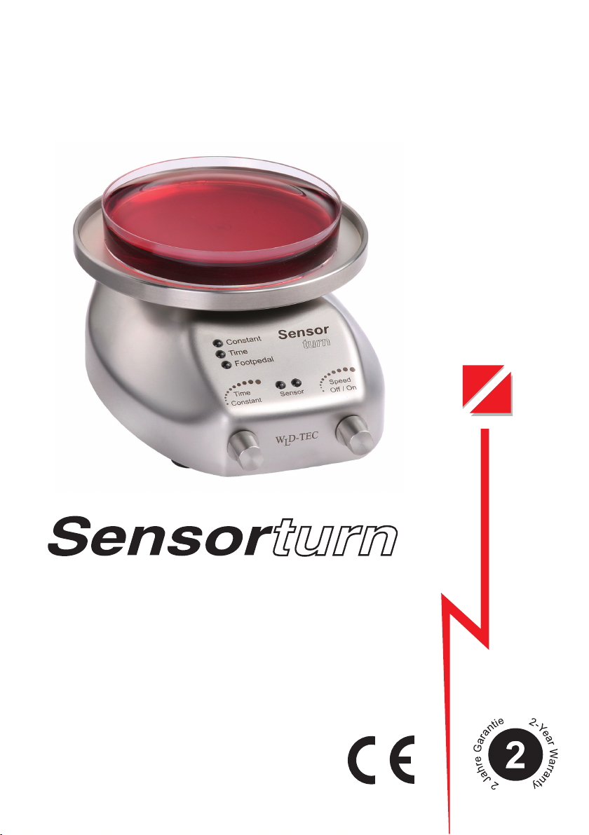
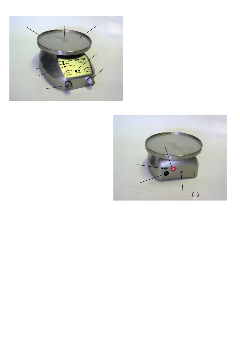
für sensorgesteuerten Drehtisch / for sensor controlled turntable
1. Elektromagnetische Verträglichkeit / Electromagnetic Compatibility Directive
1.1 EN 61326-1:2013 Elektrische Betriebsmittel für Leittechnik und
Laboreinsatz, EMV-Anforderungen
Electrical equipment for measurement, control and
laboratory use, EMC requirements
Störaussendung: Elektrische Betriebsmittel der Klasse B, Gruppe 1
Generic Emission Standard: Electrical Equipment, class B, Group 1
Störfestigkeit: Industrielle Bereiche
Generic Immunity Standard: Industrial areas
2. Sicherheit elektrischer Betriebsmittel / Security of electrical resources
2.1 EN 61010-1:2010 Sicherheitsanforderungen an elektrische Mess-, Steuer-,
Regel- und Laborgeräte. Teil 1: Allgemeine Anforderungen
Safety requirements for electrical equipment for measurement,
control, and laboratory use. Part 1: General requirements
2.2 EN 61010-2-010:2014 Sicherheitsbestimmungen für elektrische Mess-, Steuer-,
Regel- und Laborgeräte. Teil 2-010: Besondere Anforderungen
an Laborgeräte für das Erhitzen von Stoffen
Safety requirements for electrical equipment for measurement,
control, and laboratory use. Part 2-010: Particular requirements
for laboratory equipment for the heating of materials
WLD-TEC GmbH
Halle-Kasseler-Str.49
D-37318 Arenshausen
Germany
GmbH
Artur Rynkar
(Geschäftsführer, CEO)
Arenshausen, 20.03.2020
Typ / Type 7.002.000
10
Firma / Company: WLD-TEC GmbH
Gerätetyp / Typ FW8000M/09
Art.-Nr. / Part-No. 1899085 Liefervorschrift / Specification
Zeichnungs-Nr. / Draw.-No. 15.4474.500-01
www.friwo.de Index / Rev.: ⓐ Lfd. Nr. / Doc.-No. P002834048 Seite 10 von 10 / page 10 of 10
8 CE-Konformitätserklärung / Declaration of Conformity
Wir, der Hersteller, erklären hiermit, dass das Produkt: /
We, the manufacturer, hereby confirm, that the product:
Gerätetyp /
Type:
FW8000M/09
Artikel-Nr. /
Part-No.:
1899085
Zeichnungs-Nr. /
Drawing-No.:
15.4474.500-01
weitere Merkmale /
additional information:
mit der beiliegenden Beschreibung die Anforderungen der Niederspannungsrichtlinie 2006/95/EG
(gültig bis 19. April 2016) der Niederspannungsrichtlinie 2014/35/EU (gültig ab 20. April 2016),
der EMV-Richtlinie 2014/30/EG und Öko-Design Richtlinie 2009/125/EG erfüllt.
Hiermit bestätigen wir, dass unsere Produkte, unabhängig von der Produktionsstätte, RoHS- konform
produziert werden und die Anforderungen der EU Richtlinie 2011/65/EU (Neufassung der Richtlinie
2002/95/EU) erfüllen.
with the enclosed description fulfils the requirements of the Low Voltage Directive 2006/95/EC
(valid to 19. April 2016) the Low Voltage Directive 2014/35/EU (valid from 20. April 2016),
the regulations of the EMC Directive 2014/30/EC and the eco design Directive 2009/125/EC.
Hereby, we certify that our products, regardless of the production location, RoHS compliant and
fulfill the directive 2011/65/EC (revised version: directive 2002/95/EC).
Das Gerät entspricht der /
The unit corresponds to:
a) Niederspannungsrichtlinie /
Low Voltage Directive
b) EMV-Richtlinie /
EMC Directive
c) Öko Design /
ECO Design
□ EN60601-1 Ed.3 07/2007 □ EN 60601-1-2 12/2007 □ Not applicable
Ausstelldatum /
Date of issue:
22.03.2016
________________________________________ __________________________________________________
Firmenstempel / Company stamp Armin Wegener
Vice President Research & Development