6
within the device. The sphere is then pushed down
inside the barrel using the ramrod until the de-
sired spring tension has been reached. The ram-
rod should not be removed too quickly, otherwise
the suction its removal produces may pull the
sphere out with it. The position of the sphere may
only be checked using the observation holes. Never
look into the barrel!
•Before launching, ensure that no one is in the way
of the trajectory. To launch, the cord of the launch-
ing lever is briefly pulled perpendicularly to the
lever.
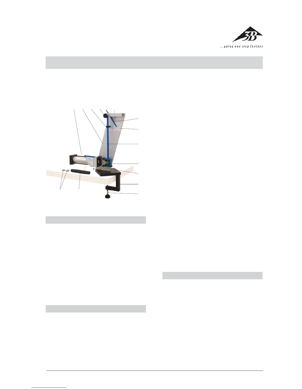
•The pendulum 8can be removed by undoing the
bearing screw 4and turned by 180° so that it is
installed with the rear of the projectile catcher
9pointing towards the launcher (experiments on
elastic collision). The counter bearing 5is designed
so that the pendulum hangs at a slight angle if the
bearing screw is only light tightened. This means
that the projectile catcher is not precisely in front
of the launch aperture of the launcher. For this rea-
son, the bearing screw should be tightened until
the catcher and the launch aperture are in line.
•After turning the pendulum round, or if necessary,
the guide 3for the swing pointer 6should be
adjusted so that the pointer just touches it when
the pendulum is suspended at rest. The screw on
the guide should only be finger-tightened to avoid
the appearance of pressure on the pendulum rod.
•Maintenance: the ballistic pendulum principally
requires no maintenance. If necessary some non-
acidic grease (Vaseline) can be applied to the bear-
ing screw 4and the knurled screw bn. Other than
in the vicinity of the scale, the apparatus may be
cleaned using acetone, ethanol (white spirit) or
petroleum ether as required. Avoid submerging the
equipment in water.
4. Experiment procedure and evaluation
4.1 Ballistic pendulum
4.1.1 Experiment setup
•The experiment setup corresponds to Fig. 1 for
experiments on inelastic collision. For experi-
ments on elastic collisions, the pendulum should
be turned round by 180° (cf. Section 3 “Opera-
tion”).
4.1.2 Experiment procedure
•It is practical for these experiments to enter the
experiment number, the spring tension (1, 2 or
3), the type of collision (inelastic “i” or elastic “e”),
the number of extra weights used and the mea-
sured angle ϕ. In order to obtain the most accu-
rate experiment results, after one shot, a second
should be performed with the swing pointer not
having been reset to 0° in between. This mini-
mizes the unavoidable frictional losses of the
swing pointer.
•Example experiment sequence:
No Spring Type of Extra Angle ϕ
tension collision weights
11 i0 17.5
22 i0 25.0
33 i0 36.0
41 i2 9.5
52 i2 13.5
63 i2 19.0
71 e0 29.5
82 e0 42.0
93 e0 60.0
4.1.3 Experiment evaluation
4.1.3.1 Inelastic collision
•The following equation is valid for the swinging
pendulum due to conservation of energy
Epot = Ekin (1)
where the potential energy is
Epot = mtot g∆h(2)
Here is mtot the total mass of the pendulum in-
cluding the projectile and any extra weights, gis
the acceleration due to gravity and ∆his the dif-
ference in height of the center of gravity of the
pendulum at rest and at the maximum extent of
its swing.
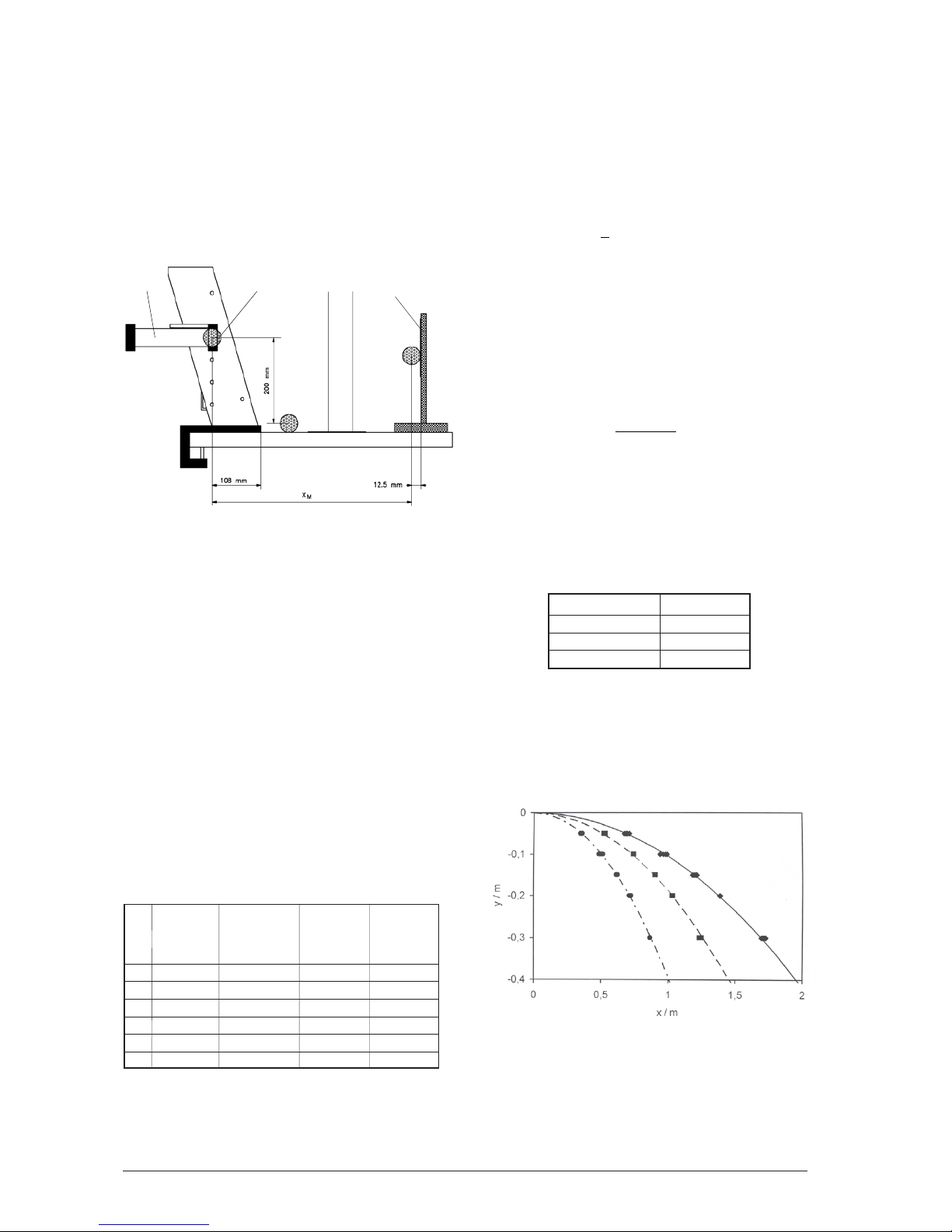
•From the measured angle ϕ and the measured
length Is to the center of gravity according to Fig.2
the following is derived:
∆h= Is(1 – cos ϕ) (3)
Fig. 2: Determining the required lengths. Distance between center of gravity
and axis of rotation (Is) should be measured including the projectile and any
additional weights when the collision is inelastic. To perform the measure-
ment, the pendulum may, for example, be balanced on a ruler mounted on
its side. The distance between the center of the projectile and the axis of
rotation is IK= 280 mm.
•The kinetic energy can be calculated from the
moment of inertia Itot relative to the axis of rota-
tion and the maximum angular speed ωaccord-
ing to the equation
EI
kin tot
=1
2
2
ω
(4)
•If Equations 2 and 4 are inserted into Equation 1
and ∆h eliminated using Equation 3 then the
equation can be rearranged to: