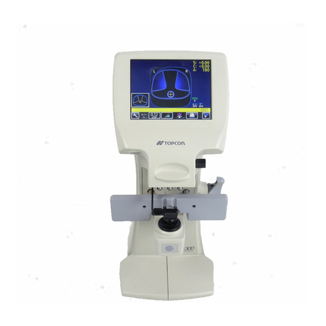
Topcon Ez METER EZ-200 User manual

INSTRUCTION MANUAL
Ez METER
EZ-200


1
INTRODUCTION
Thank you for purchasing the TOPCON EZ-200 Ez Meter.
This instrument is used to measure the power of the lenses set in the spectacle
frames.
This instrument has the following features:
•You can measure the power of the spectacle lenses for both eyes simultaneously
by means of a simple operation.
•The single-focal lens/progressive lens/bifocal lens can be detected automatically.
This manual outlines the EZ-200 Ez Meter, including operating procedures, trouble-
shooting, maintenance and cleaning.
Before using this instrument, carefully read the "DISPLAY FOR SAFE USE" and the
"SAFETY CAUTIONS" to familiarize yourself with the features of the EZ-200 Ez
Meter and to ensure that you operate it efficiently and safely.
Always keep this Instruction Manual at hand.
CAUTIONS FOR USE
•This is a precision instrument. Be sure to install and store it under controlled nor-
mal room environment conditions. Don't expose it to direct sunlight.
•Install this instrument in a level and stable place such as on a desk. Don't expose it
to direct sunlight.
•Before using this instrument, connect all the cables correctly.
•Always clean the area where you will be installing the instrument. When the instru-
ment is not in use, turn off the power and apply the dust cover.
•To get the correct measured values, be careful not to stain the test lens, or the sec-
tion which comes into contact with the lens, with dust or oil.
This symbol is applicable for EU member countries only.
To avoid potential negative consequences for the environment and possibly human
health, this instrument should be disposed of (i) for EU member countries - in
accordance with WEEE (Directive on Waste Electrical and Electronic Equipment),
or (ii) for all other countries, in accordance with local disposal and recycling laws.

2
WORKING ENVIRONMENT
Indoor use, maximum altitude: 2,000m
Degree of contamination: II (IEC 60664), working temperature range: 5 ~ 35°C
Temperature less than 31°C (40°C): linear drop to max. relative humidity of 80% (50%)
STORAGE METHOD (without package)
1. ENVIRONMENTAL CONDITIONS
Indoor use, maximum altitude: 2,000m
Degree of contamination: II (IEC 60664), working temperature range: 5 ~ 40°C
Temperature less than 31°C (40°C): linear drop to max. relative humidity of 80% (50%)
2. IF THE INSTRUMENT IS PLACED IN STORAGE, KEEP IT
(1) Free from water splashes
(2) Free from adverse effects due to atmospheric pressure, temperature, moisture, ventila-
tion, sunlight, dust, salt, sulfur, etc.
(3) Stable and free from vibration shock (including transportation) and insure that it is
always stored in an upright position.
(4) Free from chemicals and gases.
TRANSPORT AND STORAGE CONDITIONS (with package)
Temperature: -20°C ~ 50°C
Humidity: 10% ~ 95%
MAINTENANCE AND CHECKS
1. Regularly maintain and check all equipment and parts.
2. When the instrument is not in use, protect the instrument by covering it with the dust
cover.

3
DISPLAY FOR SAFE USE
To encourage safe and proper use and to prevent danger to the operator and others or potential
damage to property, important safety messages are put on the instrument body and inserted into
the instruction manual.
We suggest that everyone understand the meaning of the following displays, icons and text before
reading the "SAFETY CAUTIONS" and observe all listed instructions.
DISPLAYS
ICONS
Display Meaning
WARNING Incorrect handling by ignoring this display may lead to a risk of
death or serious injury.
CAUTION Incorrect handling by ignoring this display may lead to
personal injury or physical damage.
•Injury refers to cuts, bruises, burns, electric shock, etc. which do not require hospital-
ization or extended medical treatment.
•Physical damage refers to extensive damage to the building, nearby equipment and/
or surrounding furniture.
Icon Meaning
Prohibition
Specific content is expressed with words or a picture near the
icon.
Mandatory Action
Specific content is expressed with words or a picture near the
icon.
Caution
Specific content is expressed with words or a picture near the
icon.

4
SAFETY CAUTIONS
WARNINGS
Icon Preventive item Page
To avoid electric shock, do not attempt disassembling, rebuilding
and/or repairs on your own. Ask your dealer for repairs. 43
Do not remove the covers from the front surface, the rear surface,
the LCD display unit, etc. You may receive an electric shock. 43
To avoid fire and electric shock, install the instrument in a place free
of water and other liquids. -----
To avoid fire and electric shock, do not put cups or vessels contain-
ing liquids near the instrument. -----
To avoid electric shock, do not insert metal objects into any clear-
ances, etc. -----
To avoid fire and electric shock in case of leakage, connect the
power plug to a 3-plug AC outlet with proper grounding. 19
To avoid electric shock, be sure to remove the power cable from the
instrument body before removing the fuse cover for replacement.
Also, do not connect the power cable to the instrument body with
the fuse cover left unfixed.
53
To avoid fire in the event of an instrument malfunction, use a prop-
erly rated fuse. 53
To avoid fire in the event of an instrument malfunction, immediately
turn off the power switch and unplug the cable if you see smoke
coming from the instrument or if you detect other problems. Ask
your dealer for repairs.
-----

5
USAGE AND MAINTENANCE
USAGE
The EZ-200 Ez Meter is an electric instrument. Use this instrument according to the instruc-
tion manual.
USER MAINTENANCE
To ensure the safety and performance of this instrument, all maintenance work, unless
specified in this manual, shall be conducted by trained service engineers.
The following maintenance task may be done by the user.
For details, see the relevant part of this manual.
Replacing fuse
The fuses on this instrument may be replaced by the user. For details, refer to "Replacing
the fuse" on page 53.
ESCAPE CLAUSES
CAUTIONS
Icon Prevention item Page
Don't hold the shield cover at the bottom of the LCD display. The
instrument may be damaged. 18
To prevent the instrument from tipping over or falling and to avoid
injury, do not install the instrument on an uneven or unsteady sur-
face, including a slope. 18
To avoid electric shock, do not handle the plugs with wet fingers. 19
This instrument has been tested (with 120V, 230V) and found to
comply with IEC60601-1-2: 2004.
This instrument radiates radio frequency energy within standard
and may affect other devices in vicinity.
If you have found out by turning on/off the instrument that it affects
other devices, it is recommended to change the direction, keep a
proper distance against other devices or change the outlet.
If you have a question, consult with the selling agent.
-----
•TOPCON shall not take any responsibility for damage due to fire, earthquakes,
actions by third persons and other accidents, or damage due to negligence and
misuse by the user and any use under unusual conditions.
•TOPCON shall not take any responsibility for damage derived from inability to
properly use this instrument, such as loss of business profit and suspension of
business.
•TOPCON shall not take any responsibility for damage caused from using this
instrument in a manner other than that described in this Instruction Manual.

6
WARNING DISPLAYS AND POSITIONS
To ensure safety, the machine provides warning displays.
Use the instrument correctly by observing the display instructions. If any of the following
display labels are missing, contact your TOPCON dealer or your local Topcon office listed
on the back cover of this manual.
CAUTION
Don't hold the shield cover.
CAUTION
•Before replacing fuses, turn off
the power switch and remove
the power cable from the outlet.
•Use the specified rated fuses.

7
CONTENTS
INTRODUCTION ................................................................................................................1
DISPLAY FOR SAFE USE .................................................................................................3
ICONS .................................................................................................................................3
SAFETY CAUTIONS ..........................................................................................................4
USAGE AND MAINTENANCE ............................................................................................5
ESCAPE CLAUSES ............................................................................................................5
WARNING DISPLAYS AND POSITIONS ...........................................................................6
NOMENCLATURE
MAIN COMPONENTS ........................................................................................................9
LCD DISPLAY ...................................................................................................................10
PRINTER OUTPUT ..........................................................................................................15
STANDARD ACCESSORIES ...........................................................................................17
PREPARATIONS
INSTALLING THE INSTRUMENT ....................................................................................18
CONNECTING THE POWER CABLE ..............................................................................19
CONNECTING THE EXTERNAL INPUT/OUTPUT TERMINALS ....................................20
LOADING PRINTER PAPER ............................................................................................20
MENU SETTING ...............................................................................................................22
SETTING THE FUNCTION BUTTON ...............................................................................25
SETTING THE DATA CLEARING FUNCTION .................................................................25
SETTING DATE/TIME ......................................................................................................26
SETTING PRINT FORM ...................................................................................................27
SETTING FOR PRINTING THE SHOP NAME .................................................................28
SETTING THE SERIAL NO. .............................................................................................29
BASIC OPERATIONS
PREPARATION FOR MEASUREMENT ...........................................................................30
SETTING THE LENS MEASUREMENT MODE ...............................................................31
MEASUREMENT BY AUTO MODE .................................................................................32
MEASUREMENT BY SINGLE MODE ..............................................................................33
MEASUREMENT BY PROG MODE .................................................................................34
MEASUREMENT BY Bi-F MODE .....................................................................................35
OBJECTIVE OPERATIONS
PRINTING THE MEASURED VALUES ............................................................................36
DATA OUTPUT WITH RS-232C .......................................................................................36
DATA INPUT WITH RS-232C ...........................................................................................37
PRISM MEASUREMENT ..................................................................................................37
TRANSPOSE (POWER CONVERSION) ..........................................................................39
PROGRESSIVE ASTIGMATIC MAP MANUAL OPERATION ..........................................39
CONNECTION TO TM-1/TM-2 .........................................................................................40
BEFORE REQUESTING SERVICE
ERROR CODE ..................................................................................................................41
MESSAGE ........................................................................................................................42
TROUBLESHOOTING ......................................................................................................43
SPECIFICATIONS AND PERFORMANCE
USE AMBIENT CONDITIONS ..........................................................................................45
ELECTRIC RATING ..........................................................................................................45
8
ELECTROMAGNETIC COMPATIBILITY ..........................................................................46
SYSTEM CLASSIFICATION .............................................................................................50
DIMENSIONS AND WEIGHT ...........................................................................................50
PURPOSE OF USE ..........................................................................................................50
OPERATION PRINCIPLE .................................................................................................50
REFERENCE MATERIAL
SHAPE OF PLUG .............................................................................................................51
SYMBOL ...........................................................................................................................51
MAINTENANCE
MAINTENANCE ................................................................................................................52
CLEANING ........................................................................................................................53
DISPOSAL OF PRODUCT ...............................................................................................55

9
NOMENCLATURE
NOMENCLATURE
MAIN COMPONENTS
Luminance adjustment
volume
Power lamp
Operation button
Shield cover
Frame retainer
Printer
Power switch
Frame support
Nose rest pad retainer
Lens retainer
LCD diplay

10
NOMENCLATURE
LCD DISPLAY
MAIN display (shown in "LARGE FONT")
MAIN display (shown in "NORMAL FONT")
"PROGRESSIVE" display
Left eye lens measured values
S: Spherical power
C: Cylindricality
A: Axis angle
ADD: Addition
∆
: Horizontal/vertical prism
Right eye lens measured values
S: Spherical power
C: Cylindricality
A: Axis angle
ADD: Addition
∆
: Horizontal/vertical prism
Serial No.
button
button
button
button
PD
Frame mode
Lens measurement mode
PRINT
MODE
MEASURE
(when "AUTO" is selected)
+/--
Progressive astigmatic map
: Far point
: Near point
F
N
Addition graph
Inset quantity
Distance between
PD
button
BACK
far point and near point
Main menu

11
NOMENCLATURE
"PROGRESSIVE" manual operation display
When "ON" or "ON + PRINT" is set at "PROG. PD" in the menu, the PD value is indi-
cated on the "PROGRESSIVE" display and the "PROGRESSIVE" manual operation
display.
button (or button):
When you operate the button
SHIFT
Progressive astigmatic map
: Far point
: Near point
F
N
Addition graph
Inset quantity
Distance between
PD
button:
button (or button):
button:
Measured values:
SHIFT
NEAR POINT
button:
CANCEL
S/C/A/ADD
far point and near point
Moves the far/near point.
Changes far point to near point. Changes the button function.
Cancels operation.
Moves the far/near point.

12
NOMENCLATURE
PD input display
MENU display
button/ button:
Right eye hPD
CANCEL
PD
Left eye hPD
button:
button:
+
--
Changes the numerical value.
Selects and changes the
left eye hPD/right eye hPD/CANCEL.
Ends the PD input display.
Content of each menu:
button (Moves up)/
Changes the menu item or
button (or button):
button:
Menu items:
The selected item is
displayed in reverse. The set content is displayed
Ends the MENU display.
Selects and changes the menu
item/menu content.
in reverse.
button (Moves down):
menu content.

13
NOMENCLATURE
Date/time setting display
Print form setting display
button (positive):
Hour
Year Month
Day
Minute
button (negative)/
button:
button:
--
+
Changes the numerical value.
Changes year/month/
day/hour/minute.
Ends the date/
time setting display.
: Print
-- : Do not print
Format type
button/ button:
button:
button:
Print items
/-- Changes the print item.
Changes "Print/not print".
Ends the print form
setting display.

14
NOMENCLATURE
Shop name print setting display
TM-1/2 input display
button and
:
:
button:
button:
Cursor
Printed contents
Character list CANCEL
EXIT
/
Sets the character at the
cursor position in the list for
the printed contents. Moves the cursor.
Changes the character
list/printed contents.
button:
button:
Ends the shop name
print setting display.
Cancels the set data.
(displayed in reverse)
Spectral transmittance graph UVB UVA
Category
Visible area visibility transmittance
Comment bar
button:
button:
button:
button:
EXIT
SAVE
MODE
CIE chromaticity coordinate graph
SHIFT
Second measurement data
First measurement data
Visible area visibility transmittance
CIE chromaticity coordinate "y" value
CIE chromaticity coordinate "x" value
Changes the button function.
Ends the TM-1/2
input display.
Changes the graph. Stores the measurement data.
value value

15
NOMENCLATURE
PRINTER OUTPUT
Example of printer output for MAIN display (shown in "EZ FORMAT")
You can set the items to be outputted by the printer by using "PRINT FORM".
For details, refer to "SETTING PRINT FORM" on page 27.
Bar code
Date/time
Serial No./Instrument No.
Right eye measured values:
S: Spherical power C: Cylindricality
A: Axis angle ADD: Addition
PSM: Horizontal prism/vertical prism
Left eye measured values:
S: Spherical power C: Cylindricality
A: Axis angle ADD: Addition
PSM: Horizontal prism/vertical prism
PD value
E
xample of printer output for MAIN display (shown in "CL FORMAT")
Bar code
Date/time
Serial No./Instrument No.
Right eye measured values:
S: Spherical power C: Cylindricality
A: Axis angle ADD: Addition
PSM: Horizontal prism/vertical prism
PD value
Left eye measured values:
S: Spherical power C: Cylindricality
A: Axis angle ADD: Addition
PSM: Horizontal prism/vertical prism

16
NOMENCLATURE
Example of printer output for "PROGRESSIVE" display
When "ON + PRINT" is set at "PROG. PD" in the menu, the PD value obtained by
measuring the progressive lens is outputted by the printer.
Bar code
Date/time
Serial No./Instrument No.
Right eye measured values:
S: Spherical power C: Cylindricality
A: Axis angle ADD: Addition
PSM: Horizontal prism/vertical prism
Left eye measured values:
S: Spherical power C: Cylindricality
A: Axis angle ADD: Addition
PSM: Horizontal prism/vertical prism
Inset quantity
PD value (one eye hPD value)
Astigmatic map
Distance between
Addition graph
far point and near point

17
NOMENCLATURE
STANDARD ACCESSORIES
The standard accessories are shown below. Make sure that all the following standard accessories
are included. Figures in ( ) are the quantities.
If any of the standard accessories are not included, contact your local TOPCON office listed on the
back cover of this manual.
Instruction manual (1) Simplified instruction manual (1)
Power cable (1) Fuse (2)
Printer paper (2) Printer shaft (1)
Silicone cloth (1) Dust cover (1)
INSTRUCTION MANUAL
Ez METER
EZ-200

18
PREPARATIONS
PREPARATIONS
INSTALLING THE INSTRUMENT
1Put your hand under the side of the instrument and lift it up.
2Hold the specified positions of the instrument securely with both hands and install it in a
stable place.
CAUTION Don't hold the shield cover at the bottom of the LCD display. The
instrument may be damaged.
CAUTION To prevent the instrument from tipping over or falling and to avoid
injury, do not install the instrument on an uneven or unsteady sur-
face, including a slope.
Place where you
should not hold
EZ
-200
Place where you should hold
Place
Places where
How to hold the instrument
you should not hold
where you
should hold
Table of contents
Other Topcon Measuring Instrument manuals

Topcon
Topcon CA-200F User manual

Topcon
Topcon DIGI-STAR TMR3610 User manual

Topcon
Topcon KR-1W User manual

Topcon
Topcon ES-101 User manual

Topcon
Topcon RL-HV Series User manual

Topcon
Topcon GPT-7000i Series User manual

Topcon
Topcon RL-SV2S User manual

Topcon
Topcon RC-5 User manual

Topcon
Topcon Synergy GM-50 series User manual

Topcon
Topcon RL-VH3A User manual

Topcon
Topcon BM-7AC User manual

Topcon
Topcon ES-62 User manual

Topcon
Topcon KR-1 User manual

Topcon
Topcon RL-VH4DR/G2 User manual

Topcon
Topcon DS Series User manual

Topcon
Topcon GTS-230 Series User manual

Topcon
Topcon AT-G4 User manual

Topcon
Topcon GTS-710 Series User manual

Topcon
Topcon RL-H5A User manual

Topcon
Topcon EZ2810 User manual