Topdon PulseQ AC Home User manual

AC EV Charger
User Manual


Abbreviations
Contents
International Electrotechnical Commission
Electrical Vehicle, this can be BEV (battery EV) or PHEV (plug-in hybrid EV)
Electric Vehicle Supply Equipment [IEC61851-1]
On-board charger (of an EV)
Kilo Watt (unit of Power)
Ampere (unit of Current)
Volt (unit of Voltage)
Hertz (unit of Frequency)
Liquid Crystal Display
Light-emitting Diode
Abbreviations
Section 1—PRECAUTIONS
Section 2—STANDARDS COMPLIANCE
Section 3— PRODUCT OVERVIEW & INFO
Section 4—What's in the Box?
Section 5—Installation
Section 6—Network Conguration
Section 7—LED Indicators
Section 8—Fault Handling
Section 9—Warranty
3
4
7
9
13
14
24
28
29
30
....................................................................................................
....................................................................................................
....................................................................................................
....................................................................................................
....................................................................................................
....................................................................................................
....................................................................................................
....................................................................................................
....................................................................................................
....................................................................................................
IEC
EV
EVSE
OBC
KW
A
V
Hz
LCD
LED
1
2
3
4
5
6
7
8
9
10
Human-Machine InterfaceHMI13
Central Management System, manages EVSE and has the information for
authorizing users for using its EVSE.
CMS11
Open Charge Point Protocol
A standard open protocol for communication between EVSE and a Central
System and is designed to accommodate any type of charging technique.
(www.openchargealliance.org)
OCPP12
S/N Abbreviations Description
3

Section 1—PRECAUTIONS
1.1 IMPORTANT SAFETY PRECAUTIONS
4
WARNING- When using electric products, basic precautions should always be followed, including
the following. This manual contains important instructions for Models and PULSEQ AC HOME that
shall be followed during the installation, operation, and maintenance of the charging station.
Read all the instructions before using this product.
This device should be supervised when used around children.
Do not put ngers into the electric vehicle connector.
Do not use this product if the exible power cord or EV cable is frayed, has broken insulation, or has
any other signs of damage.
Do not use this product if the enclosure or the EV connector is broken, cracked, open, or shows any
other indication of damage.
Indicate the ambient temperature rating, (-30°C to 55°C ).
"CAUTION" and the following or equivalent: "To reduce the risk of re, connect to a circuit provided
with maximum branch circuit overcurrent protection of 40A 1-Phase/20A 3-Phase/40A 3-Phase in
accordance with electrical code."
6.
7.
5.
4.
1.
2.
3.
Current RatingModel
40A 1-Phase
20A 3-Phase
40A 3-Phase
PulseQ AC Home_7K_EU
PulseQ AC Home_11K_EU
PulseQ AC Home_22K_EU
5
1.2.1 Safety signs used
The following warning signs, mandatory signs and information signs are used in this manual, on and in the AC EV
Charger.
CAUTION: Warning of electrical hazards.
This sign is intended to alert the user that severe personal injury or substantial property damage can
result if the device is not operated as requested.
ATTENTION: Warning of a dangerous spot or dangerous situation.
This sign is intended to alert the user that minor personal injury or material damage can result, if the
device is not operated as requested.
CAUTION: Do not touch by hands in case of ESD.
Indicates the possible consequences of touching electrostatically sensitive components.
No access for unauthorized persons.
Use protective footwear.
Must wear a safety helmet.
Indicates important texts, notes, or tips.
1.2 SAFETY NOTES
Safety protection must be done when installing the EV Charger.
Installation must be carried out by personnel with professional qualication, otherwise there is a risk
of electric shock.
It shall be installed in the place without violent vibration and impact, and placed vertically to facilitate
ventilation.
It shall be installed on noncombustible materials, or there is a risk of re.
Do not drop any foreign objects, especially metal objects, into the inside of the Charger or there is a
risk of re.
The lead nose of the Charger must be securely attached or there is a risk of damaging the equipment.
1.2.2 Safety Precautions for Installation

Strictly forbidden for minors or persons of restricted capacity to approach the Charger to avoid injury.
Forced charging is strictly forbidden when the electric vehicle or Charger fails.
The electric vehicles can only be charged with the engine off and stationary. Do not charge in rainy
and thunderous weather.
It is strictly prohibited to use the charger when the charging adapter or charging cables are defective,
cracked, worn, broken or the charging cables is exposed. If you nd any, please contact the supplier in
time.
1.2.4 Safety Precautions for Maintenance
Personnel must always use protective footwear when maintenance work.
It is recommended that routine safety inspection visits to Charger be conducted at least once a week.
Do not put inammable, explosive, or combustible materials, chemicals, combustible steam, and
other dangerous goods near the Charger, otherwise there is a risk of re.
Keep the charging adapter clean and dry and wipe with a clean, dry cloth if soiled. Do not touch the
Charger with your hand when charged.
1.2.3 Safety Precautions for Maintenance
6

7
Section 2—STANDARDS COMPLIANCE
2.1 Standard(s) for safety
2.2 Charging mode and connection
Conform to IEC 61851, IEC 62196
Charging station
Cable
According to IEC 61851-1, the Charging mode of PulseQ AC Home is Mode 3, and charging connection is the Case C.
Mode 3
a method for the connection of an EV to an AC EV supply equipment permanently connected to an
AC supply network, with a control pilot function that extends from the AC EV supply equipment to
the EV.
Case C:
Connection of an EV to a supply network utilizing a cable and vehicle connector permanently
attached to the EV charger.
Vehicle inlet
Vehicle
connector

8
2.3 Charging interface
The charging plug of PulseQ AC Home product meets IEC 62196-2, Type 2.
PulseQ AC Home provides a Type 2 female plug with charging cable, it only charging an EV with a Type 2 charging
socket (vehicle inlet).
Fig. 2.3.1 Schematic diagram of Type 2 interface
CP
NPE L1
L3 L2
PP
9
Section 3— PRODUCT OVERVIEW & INFO
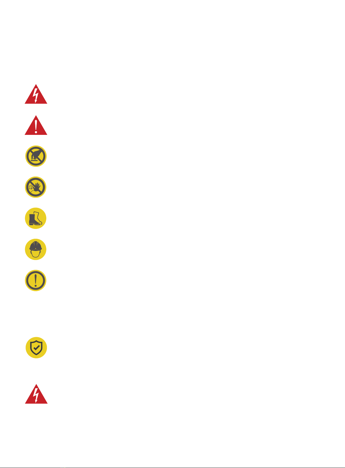
3.1 Shape & Dimensions
3.2 Block diagram
The shape & dimensions of PulseQ AC Home charger are shown as Fig. 3.1.1
The block diagram of PulseQ AC Home charger is shown as Fig. 3.2.1
LED
RCMU
type A+
6mADC
RFID reader
PT&CT
RS-485
WiFi
or
Bluetooth
Charging
interface
Fig. 3.1.1 The shape & Dimensions of PulseQ AC Home
220mm
310mm
95mm
Main CPU

10
3.3 Specications
It is widely used in various household electric vehicle charging in Europe, as well as various chargers, parking lots,
community garages and public electric vehicle charging places.
3.3.1 Electrical Specications
3.3.2 Functional Description
230V/400V, 50/60Hz
32A 1-Phase/16A 3-Phase/32A 3-Phase
7kW/11kW/22kW
IEC 62196-2, Type 2 plug with 5m cable/IEC 62196-2, Type 2 optional plug with 7.5m cable
Note: That cord extension sets are not be used.
PULSEQ AC HOMEModel Number
Rated Voltage
Rated Current
Rated Power
Safety Protection
RCD Built-in
Charging Interface
Mode 3
Remote: APP-controlled
Local: Plug and charge
RFID Reader mode
4 LED lights;
Indicate 4 statuses include standby, charging, fault, and network
WiFi(2.4GHz/5GHz)
And support OCPP 1.6J Protocol (Optional)
RS-485 with special communication protocol
Surge protection, over temperature, over/under voltage, over current, ground protection
RAMU, Type A IΔn=30mA + IΔdc=6mA
Charging Mode
Charging Control
Indicator Lights
Communication
Interface
Communication
Interface (Optional)

3.3.3 Mechanical Parameters
3.3.4 Ambient Conditions
Wall-mounted
≤ 7KG(5m cable)、≤ 9KG(7.5m cable)
H×W×D = 310mm × 220mm × 95mm
Front cover: Gray, PC; Back cover: Black, PC
IP65
IK10
≤ 2000m
-40 ~ 75℃
-30 ~ 55℃
≤ 95%RH, no water droplet condensation
<0.5G, no acute vibration and impaction
Indoor or outdoor, good ventilation, no ammable, explosive gases
Mounting
Net Weight
Dimension
Color & Material
IP Code
IK Code
Altitude
Storage Temperature
Operation Temperature
Relative Humidity
Vibration
Installation Location
11

Model No.:
Rated Voltage:
Rated Current:
Rated Power:
IP code:
Temperature Rating:
PulseQ AC Home_7K_EU
PulseQ AC Home_11K_EU
PulseQ AC Home_22K_EU
230V/400V, 50/60Hz
32A 1-Phase/16A 3-Phase/32A 3-Phase
7kW/11kW/22kW
IP 65
-30~55℃(-22~131℉)
12
3.3.5 Nameplate
This equipment should be reliably grounded before use.
Installation, wiring and maintenance should be done by personnel with professional qualication.
Do not expose to ammable gas.
Failure to read user manual carefully before use may lead to improper operation.
1.
2.
3.
4.

Section 4—What's in the Box?
AC EV Charger (5m charging cable)
Charging Dock
Wall-mounting Accessories
User Manual
Quick User Guide
Quality Certicate
Wall Installation Template
M6×63mm Expansion Bolt
M5×40mm Expansion Bolt
Charging Dock Installation Template
IC card
1
1
1
1
1
1
1
4
4
1
2
a.
b.
c.
d.
e.
f.
g.
h.
i.
j.
k.
a
g
d e f
j k
cb
h
i
13
User
Manual
IC card
Section 5—Installation
5.1 Pre-Installation Inspection
5.2 Pre-work Preparation
When unpacking, please carefully conrm the following points:
● Whether the accessories are missing according to the packing list.
● Whether there is any damage during transportation.
● Whether the model and specication of the machine's nameplate are consistent with the order requirements.
When transporting or moving the EV charger, pay attention to the following points to ensure product safety:
In order to ensure the long-term stable operation of the product, it is recommended to avoid installing
chargers in extreme weather as far as possible, especially the low or high ambient temperatures may affect the
installation effect due to thermal expansion and cold contraction.
Space requirement: When the charger is xed on the wall, the minimum space requirements are shown in Fig.
5.2.
It is suggested that the charger should be installed in a place with good ventilation, no direct sunlight and
shelter from wind and rain. In order to ensure good ventilation condition, you should mount the charger
vertically and leave enough space.
Fig. 5.2 Minimum space requirements for wall mounting
If any damage or missing parts are found, please do not start the installation, and contact us as soon
as possible.
Please keep the packing box and packing materials for 1 month for future handling.
The paper packaging is recyclable.
This product is electrical equipment. It should be handled with care to avoid violent vibration and
impact.
The charger shall not be transported by dragging the charging connector and the charging cable.
14
200mm
(min)
200mm
(min)
200mm
(min)
≈1200-1400mm

5.3 Tools for Installation
Please prepare the following tools before installation
Check the electrical connection and
measure the voltage
Multimeter1
Fastening boltWrench3
Peeling cablesWire stripper5
Drill xing holes in the wall
Electric Impact
drill
2
Cut the cableDiagonal plier4
Pressed cable terminalCrimping plier6
Fastening screwCross screwdriver7
No. Tools’ Name Schematic Picture Main Uses
15
5.4 Wall Bracket Installation
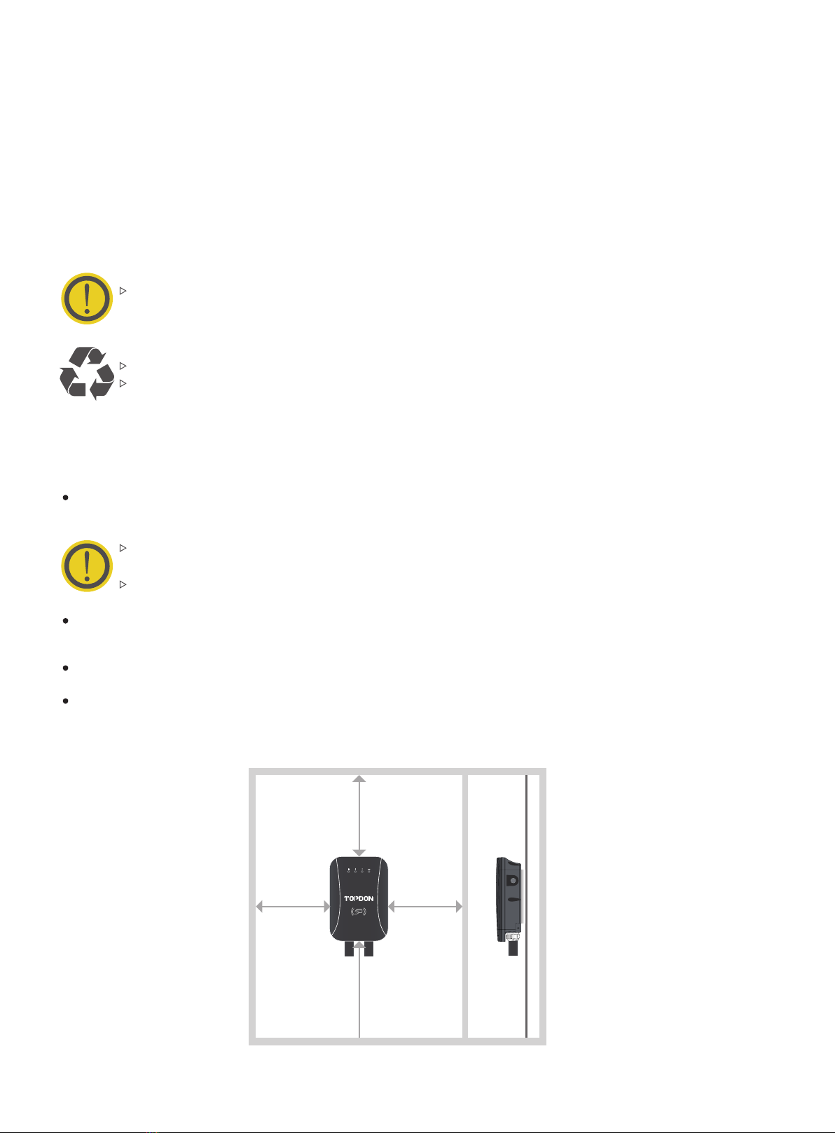
Ensure the homeowner has chosen an installation location that allows the charging cable to reach the car's
charging port while still providing slack. Ensure there is a stud available at the desired location for mounting he
charging station. (See Fig. 5.4.1) Ensure there is WiFi signal available.
Refer to the Fig. 5.4.2 to understand the dimensions of the wall bracket. Please make sure the space on the wall
is at least 5.62" × 5.98" (143mm × 152mm).
Fig. 5.4.1
Fig. 5.4.2
1.
WARNING: In areas with frequent thunderstorms, add surge protection at the service panel for all
circuits. Ensure all power and ground connections, especially those at the breaker and bus bar, are
clean and tight. Remove all oxide from all conductors and terminals before connecting wiring.
143mm
152mm
16
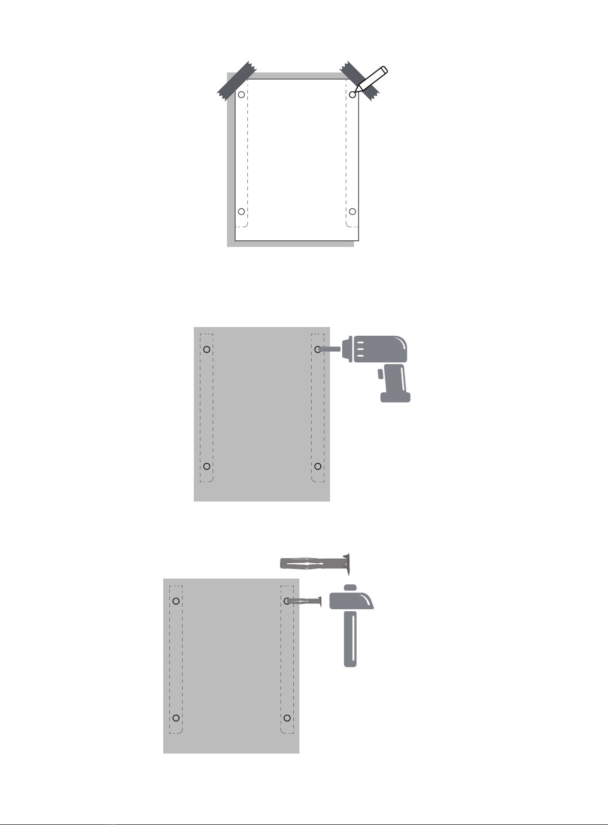
Mark the mounting hole on the wall with the installation template. (See Fig. 5.4.3)
Drill the mounting holes on the wall with a depth of at least 1.97". (See Fig. 5.4.4)
Hammer the expansion sleeve into the corresponding hole (See Fig. 5.4.5)
2.
3.
3.
Fig. 5.4.3
Fig. 5.4.4
Fig. 5.4.5
1.97"
17

Fix the bracket to the wall with the expansion screws (See Fig. 5.4.6) included in the package.
Attach the charger to the bracket.(See Fig. 5.4.7)
5.
6.
Fig. 5.4.6
Fig. 5.4.7
18

Unscrew the gland at the bottom of the charging station. Pass the prepared power cable through it. (See Fig.
5.5.2)
2.
Fig. 5.5.2
5.5 Hardwire Installation
The hardwire installation needs to be done by electricians, and please strictly follow the safety
precautions.
Unscrew the six screws on the back cover with a Phillips screwdriver, and remove the front cover.
(See Fig. 5.5.1)
1.
Fig. 5.5.1
19
L3
L2
L1
N
PE
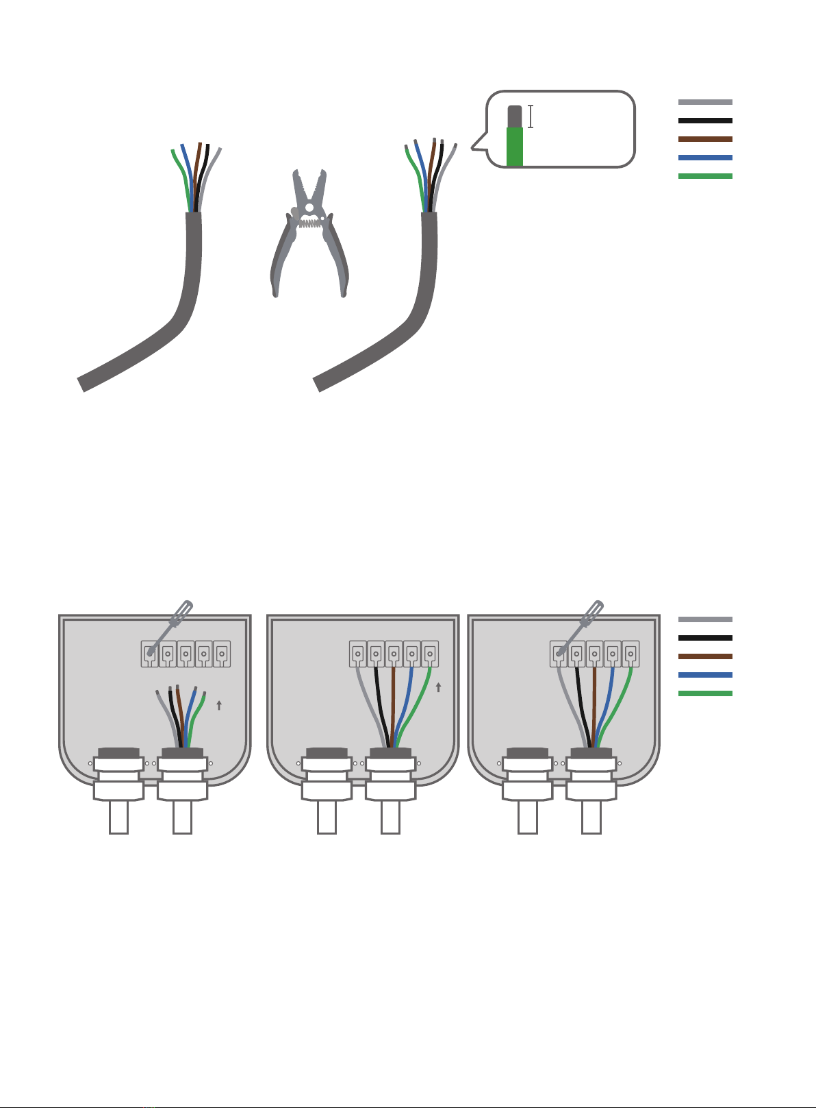
Use a wire stripper to remove 10~12 mm of insulation from the wire conductor. (See Fig.5.5.3)3.
Fig. 5.5.3
Turn over the wirebox. Loosen the ve screws with a at-blade screwdriver and fully insert the wire conductors
into the connectors on the terminal block. Tighten the screws and make sure each wire conductor is securely
connected. (See Fig.5.5.4)
4.
Fig. 5.5.4
20
L3
L2
L1
N
PE
L3
L2
L1
N
PE
10-12mm
Note: For the model of PulseQ AC Home_7K_EU, only connect the corresponding wire conductors to the L1, N,
PE connectors.
Table of contents
Other Topdon Automobile Accessories manuals


Popular Automobile Accessories manuals by other brands


Cruz
Cruz Evo Rack Pro P20-126 Assembly instructions

aqprox!
aqprox! appUSBCAR24B user guide

RBO
RBO RBO3015 product manual

AMP Research
AMP Research PowerStep 77238-01A installation guide

HUSKY LINERS
HUSKY LINERS 2179FR Care and use instructions

Prolux
Prolux Skyline AIR S Installation maintenance and service manual

Momento
Momento MR-S100 quick start guide

Safe Fleet
Safe Fleet Prime Design VCI 226 Assembly instructions

Dakota Digital
Dakota Digital VHX-1023 Installation

Metra Electronics
Metra Electronics 99-7318 installation instructions

Tessera4x4
Tessera4x4 SOT-ROLL Series installation manual

Advent
Advent MITBTSW2 owner's manual