Topens ET24 User manual

1
Electric Lock User’s Manual
Model:
TOPENS Website
www.topens.com
C030426
ET24
VER 21a

2
Important Note:
The open delay time of the 2 actuators must be set to more
than 4S if the electric lock is used with dual swing gate
opener which is powered by the DPS180-U AC-DC power
supply, or the gate opener would work improperly.
Electric lock improves the safety for your gate, and it is
highly recommended if you have animals or live in areas
affected by strong winds when the gate is longer than 1.5
meters (7ft).
Electric Lock Part List
Important Information:
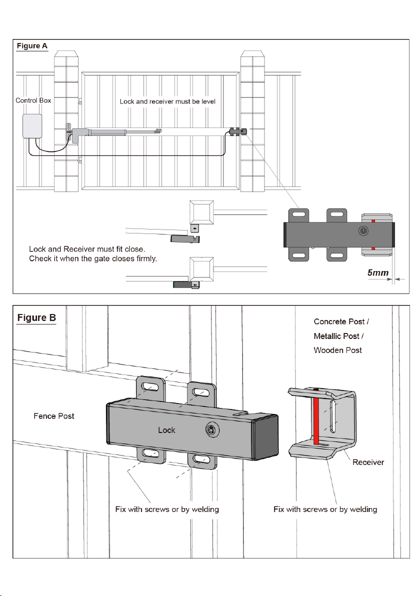
1. Before you install the Electric Lock please be sure the gate is level,
moves freely, and does not bind or block against barriers.
2. On the Pull-to-Open installation, for the Electric Lock to work
properly, in order to ensure the lock engaging with the lock receiver
firmly, the limit switch B must be moved outward a little bit more than
the desired close position.
3. The Electric Lock must be installed on the outside of the gate if on the
Push-to-Open gate.
4. Due to the various mounting conditions, mounting hardware is not

3
provided. Read this manual carefully to determine the mounting hardware
required for your condition.
5. For dual gate, the lock must be installed on the Master Gate (gate 1)
which is near the Control Box, and the lock receiver must be installed on the
Slave Gate (gate 2).
( If the gate near the control box has been set up as slave gate, you can
change the settings following “User’s Manual” →“Control Board Settings”
→“Master/Slave Gate Set” )
Installation for Single Gate
Step 1: Disengage the clutch of the opener with the Release Key. You
can move the gate by hand, so the gate can swing freely during
installation of the Electric Lock.
Step 2: With the gate in the closed position, determine the best location for
the lock and receiver. The lock and receiver must be level and aligned with
the opener. The lock and receiver should have a solid surface or tube fence
to provide stability.
Step 3: For Metallic Tube gate, if the thickness of the fence post is bigger
than or equal to 3mm, you can thread on the fence post, and fasten the lock
and receiver only using bolts (without nuts). Otherwise, drill holes through
out the fence post, and fasten the lock and receiver with bolts, lock washers
and nuts.
Of course, you can weld them directly.
For Chain Link gate, you will need U-Bolts, saddles, lock washers and nuts
for the lock and receiver.
Step 4: Recheck the lock’s position and alignment, make sure the electric
lock work correctly.
Step 5: Connect the lock’s power cables to E-Plus board or the control
board of TOPENS swing gate opener refers to the chapter “Wire
Connection of the LOCK”.
Note: Be sure that the clutch of the opener is engaged before you
prepare to activate your opener (Use the Release Key).
4

5
Installation for Dual Gate
Step 1: Disengage the clutches of the openers with the Release Key.
You can move the gates by hand, so the gates can swing freely during
installation of the Electric Lock.
Step 2: With the gates in the closed position, determine the best location
for the lock and receiver. The lock and receiver must be level and aligned
with the openers. The lock and receiver should have a solid surface or tube
fence to provide stability.
Step 3: For Metallic Tube gates, if the thickness of the fence post is bigger
than or equal to 3mm, you can thread on the fence post, and fasten the lock
and receiver only using bolts (without nuts). Otherwise, drill holes through
out the fence post, and fasten the lock and receiver with bolts, lock washers
and nuts.
Of course, you can weld them directly.
For Chain Link gates, you will need U-Bolts, saddles, lock washers and
nuts for the lock and receiver.
Step 4: Recheck the lock’s position and alignment, make sure the electric
lock work correctly.
Step 5: Connect the lock’s power cables to E-Plus board or the control
board of TOPENS swing gate opener refers to the chapter “Wire
Connection of the LOCK”.
Note: Be sure that the clutches of the openers are engaged before
you prepare to activate your openers (Use the Release Key).

6

7
Wire Connection of the Lock
1. Wire Connection for A&AD&PW Series Swing Gate Opener
The E-Plus board must be used with the E-Lock when it’s connected to
the A&AD&PW swing gate opener. The E-Plus board is in the small box
which is included in the package. J3 of the E-Plus board and the electric
lock have the wiring connector. You can place the E-Plus board in the
control box and then plug the J3 of the E-plus board to the electric lock
directly. The other 2
set wires of the
E-Plus board should
be connected to the
control board as the
following wiring
diagram or the wiring
diagram in the
manual of gate opener.
Wiring Diagram of the
E-Lock to the A Series
Swing Gate Opener

8
Wiring Diagram of the E-Lock to the AD&PW Series Swing Gate
Opener
9
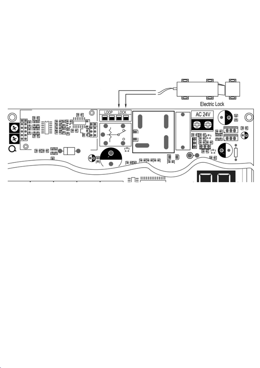
2. Wire Connection of the Lock for KD 902 & AT1202 Series
Swing Gate Opener
The E-Plus board is not needed to use with the two gate openers. The
electric lock can be wired to the “LOCK” terminal directly, no matter the
polarity of the wires.
Wiring Diagram of the E-Lock to the KD902 & AT1202 Swing Gate
Opener
NOTE: If the gate opener which you want to use the lock with is not
listed in the above diagram, you can find the wiring diagram in the
user manual of the gate opener or you can contact us to provide
technical support.

10
TOPENS Website
www.topens.com
Any question, please do not hesitate to contact us:
E-mail: support@topens.com
Kindly include your Product Model, Purchasing Date & Site, Order #,
and your contact information. All your concerns will be replied within
24 hours.
Tel: +86 (571) 8908 0213 (China)
Mon-Fri 9:00AM-5:30PM (UTC +08:00)


