TOPINOX Ultravent VarioCooking Center 112 User manual
Ultravent®
VarioCooking Center® 112
Version 05
02/2013

- 2 - V 05

- 3 -
V 05
FInstructions de montage et schémas de réservations 4-9 et 10-13
D
Installationsanleitung und Zeichnungen 4-9 und 14-17.
GB
Installation instruction and schematic drawings 4-9 and 18-21.
.EInstrucciones de instalación y gráficos 4-9 y 22 - 25
CZ Návod pro instalaci a výkresy 4-9 a 26-29
NL Installatiehandleiding en tekeningen 4-9 en 30-33
F
Instruction de service succincte
34-36
D
Kurzbetriebsanleitung 37-39.
GB
Brief operating instruction 40-42
.E
Manual breve de instrucciones de servicio 43-45
CZ Krátký provozní návod 46-48
NL Beknopte gebruiksaanwijzing en tekeningen 49-51

- 4 - V 05
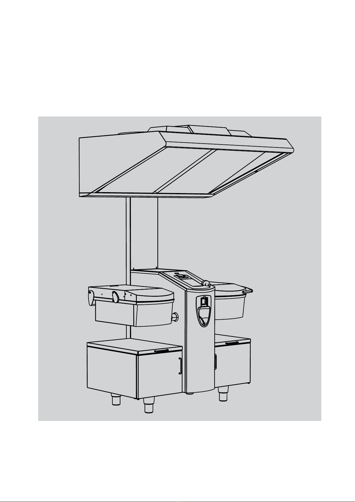
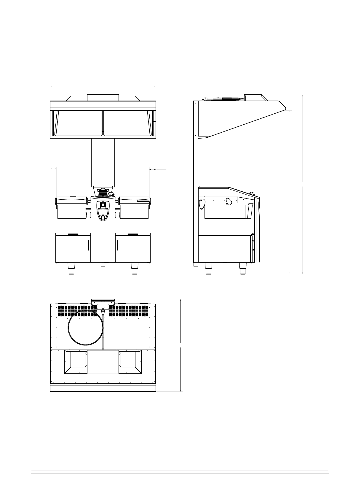
Masszeichnung Ultravent®für VarioCooking Center®112
Dimension drawing of Ultravent®for VarioCooking Center®112
350
150
1565
40
42
176
111061
937
400
1340
142
710
126
Ǿ11
300
554
1171
2119
50
50
min. 300mm
- 5 -
V 05
Masszeichnung Ultravent®/VarioCooking Center®112
Dimension drawing of Ultravent®/VarioCooking Center®112
2269
2070
1171
86
86
1340

- 6 - V 05
-S1
3x1,5 mm2
S
tufe 2 0
BN
2
1
St uf e 4
L1
-X1
L1
6,3A
-F1
13
14
BN
23
24
43
44
53
54
BU
315mA
-F2
BK BK
-T1
-M1
WH
Pri.
Sec.
-X1
1
1
RD
230V
11,5V
2
2
GY
200V
3
3
M
BK
4
4
215W
0V
0V
Block
B0002185
50-60Hz 20VA
BU
-H1
BN
BU
5
N
10W
12V
-H1
X2
X1
GN/GE
6
PE
BU
BN
-H2
-M2
WH
-X1 1
1
10W
12V
-H2
X2
X1
RD
2
2
GY
3
3
M
BK
N
-X1
N
4
4
BU
215W
N
BU
N
5
N
GN/ GE
PE
-X1 PE
6
PE
GN/ GE
PE
PE
MASCHINE
Schéma électrique / Stromlaufplan / Wiring diagram

- 7 -
V 05
Pos Référence
Artikelnr.
Part no.
Désignation Bezeichnung Designation
F1 3019.0122V Fusible 6,3A MT Sicherung 6,3A MT Fuse 6,3A MT
F2 3019.0135V Fusible 0,315A MT Sicherung 0,315A MT Fuse 0,315A MT
M1 3101.1019V Moteur gauche Motor links Motor left
M2 3101.1019V Moteur droit Motor rechts Motor right
87.00.358 Filtre à graisse pour
moteur
Fettfilter für Motor Filter grease for
engine
H1 3024.0201V Lampe halogène
10W/12V
Halogenlampe
10W/12V
Halogen bulb
10W/12V
H2 3024.0201V Lampe halogène
10W/12V
Halogenlampe
10W/12V
Halogen bulb
10W/12V
40.00.091V Cadre avec vitre et
joint
Andrückrahmen kpl. Gasket frame w.
glass a. gaskets
40.00.098V Réflecteur d'éclairage Reflektor Beleuch-
tung
Reflector for light
T1 3037.0204V Transformateur
d'éclairage 20VA
Halogentrafo 20VA Halogen trans-
former 20VA
S1 82.00.273 Sélecteur Ultravent Schalter Ultravent Selector Ultra-
vent
Couleur
Farbe
Color
Désignation Bezeichnung Designation
BN Brun Braun Brown
BU Bleu Blau Blue
GY Gris Grau Grey
GN Vert Grün Green
RD Rouge Rot Red
BK Noir Schwarz Black
WH Blanc Weiss White

- 8 - V 05
2
8
1 2
3
4
1
5
67
3 A
4
4B
3 B
A
3
- 9 -
V 05
5
5A
5B
6
7
8
9
10
- 10 - V 05
F
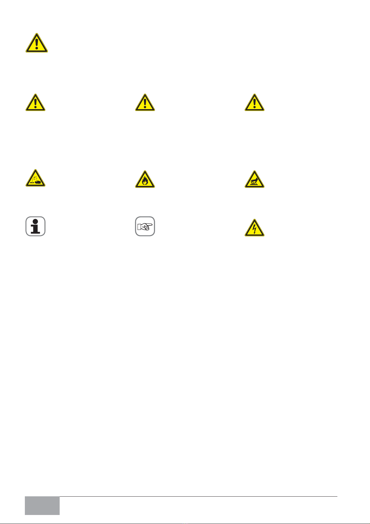
Consignes de sécurité
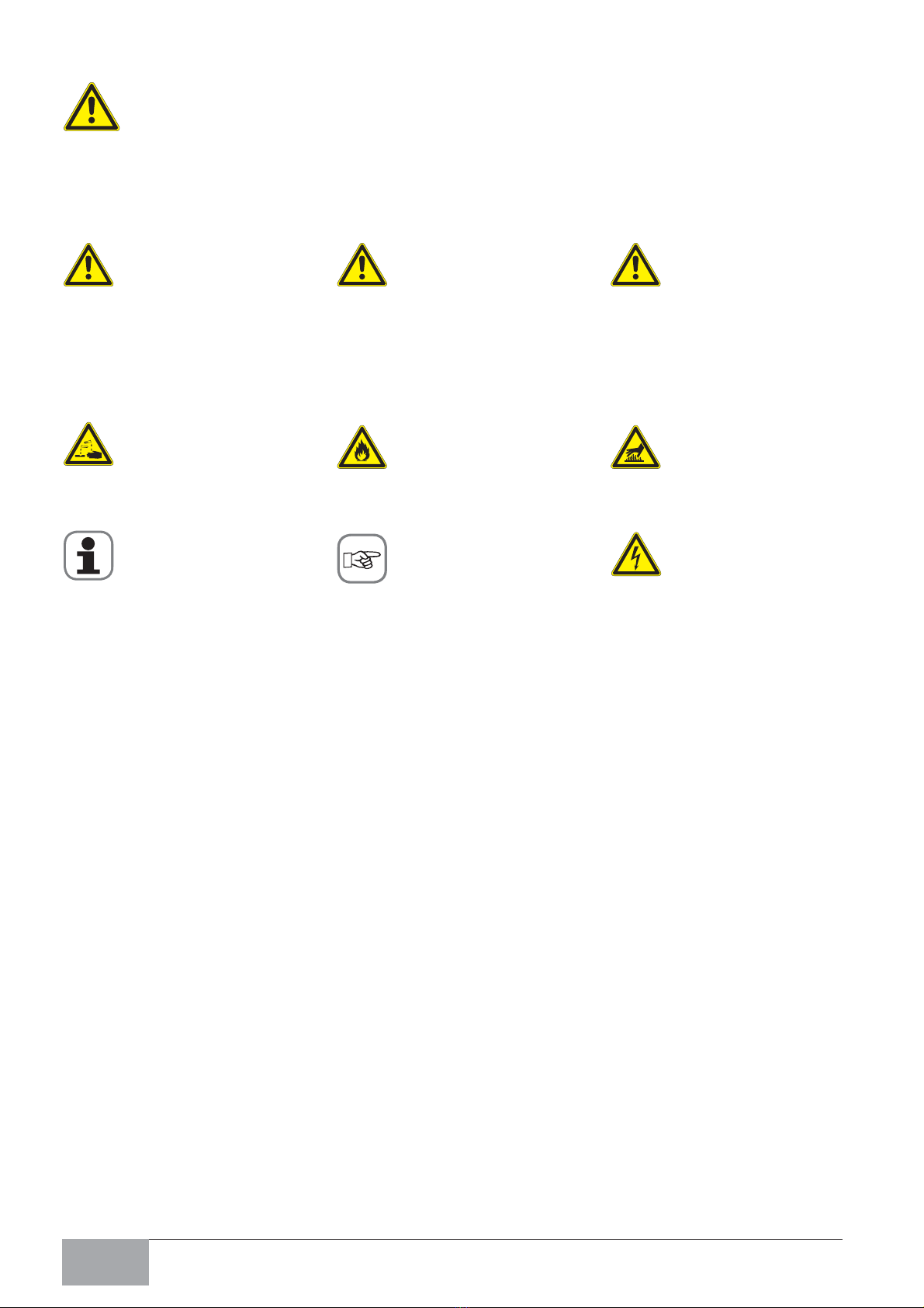
Danger !
Indique une situation
dangereuse susceptible
d‘entraîner des blessures
très graves ou la mort.
Matières corrosives
Attention : un non-respect
peut entraîner des
dommages matériels.
Attention !
Indique une situation
potentiellement dangereuse
et susceptible d‘entraîner
des blessures graves ou la
mort.
Risque d‘incendie !
Conseils et astuces pour
l‘installation.
Prudence !
Indique une situation
potentiellement dangereuse
susceptible d‘entraîner des
blessures légères.
Risque de brûlure !
Danger !
Haute tension.
Attention Danger de mort
Un non respect peut
entraîner des blessures très
graves ou la mort.
Explication des pictogrammes
- 11 -
V 05 F
Attention:
Si l‘installation, le réglage, le dépannage ou la maintenance ne sont pas effectués
correctement, et si des modifications sont apportées à l‘appareil, cela pourra entraî-
ner des dommages, des blessures ou même la mort. Veuillez lire attentivement le
présent manuel avant la mise en service de l‘appareil.
Il est impératif d’observer les consignes de sécurité suivantes:
Norme applicable: EN 60335-2-99
- Il est nécessaire de prévoir une ventilation suffisante du local lorsque la hotte
Ultravent®est utilisé en même temps que des appareils à combustion de gaz ou
d‘autres combustibles.
- Il est interdit de flamber au-dessous de la hotte.
- Respecter strictement les prescriptions en matière de ventilation et d’évacuation de
l’air.
- Faire particulièrement attention lorsque d’autres appareils à tirage ouvert se trouvent
dans le même local pour empêcher tout retour d’aspiration des gaz de combustion.
- L’utilisation de cette hotte Ultravent®ne remplace pas l’évacuation prescrite des gaz
de combustion via une hotte, cheminée ou un plafond diffusant (plafond de ventilation)
séparé.
- Lorsque l’évacuation des gaz de combustion d’un appareil à gaz intervient via une
hotte ou un plafond diffusant (plafond de ventilation), il est nécessaire, conformément
aux prescriptions nationales en matière de gaz, de prévoir l’installation d’un dispositif à
rappel non automatique permettant de couper l‘alimentation en gaz vers l‘appareil lors-
que l‘installation d‘évacuation de l‘air cesse de fonctionner.
- Veiller à ce que l’installation de la hotte Ultravent® soit conforme à la législation applica-
ble en matière de gaz.
Attention!
Tout dommage résultant du non respect des présentes directives est exclu de la
garantie.
Les raccordements nécessaires (eau et électricité) doivent être faits uniquement par des
professionnels conformément aux prescriptions locales.
Le niveau sonore est inférieur à 70dB(A) pour une exploitation normale de l’appareil.
Elimination des appareils vétustes
Au terme de sa durée de service, l’appareil ne doit ni être éliminé avec les déchets /
ordures ménagères ni être déposé dans les conteneurs de récupération des appareils
vétustes mis en place par les communes.
Nous restons à votre disposition pour vous aider à procéder à une élimination conforme
de l’appareil
Contrôle à réception
Contrôler l‘appareil pour vérifier s‘il n‘a pas été endommagé durant le transport. En cas
de doute, informer immédiatement votre revendeur / transporteur !
Avant mise en service retirer tous les cartons, emballages, documents etc.
- 12 - V 05
F
Cher client,
nous vous prions de bien vouloir lire atten-
tivement les présentes consignes d’instal-
lation. Tout dommage dû au non-respect
des présentes consignes d’installation est
exclu de la garantie.
Ultravent®complet 60.70.804
Pièces Fig. 1
Pos.Désignation Réf.:
1 Profil porteur 36.003.686
2 Couvercle profil porteur 36.003.685
3 Profil porteur plaque
de retenue 36.003.699
4 Tuyau HT 60.70.896
5 Couvercle tuyau HT 2070.0053
6 Entretoise alu 10.00.762
7 Ecrou alu M8 10.00.761
Pièces Fig. 2
Pos.Désignation
8 Ultravent 60.70.891
Installation
1.Livraison
Déballez avec soin l’appareil livré et assu-
rez-vous qu’il n’a pas souffert du transport.
2. Installation
Prudence !
Attention au poids des appareils. Utilisez
des supports de transport.
Poids net:
Ultravent®112 145 kg
Ultravent®211 153 kg
Ultravent®311 246 kg
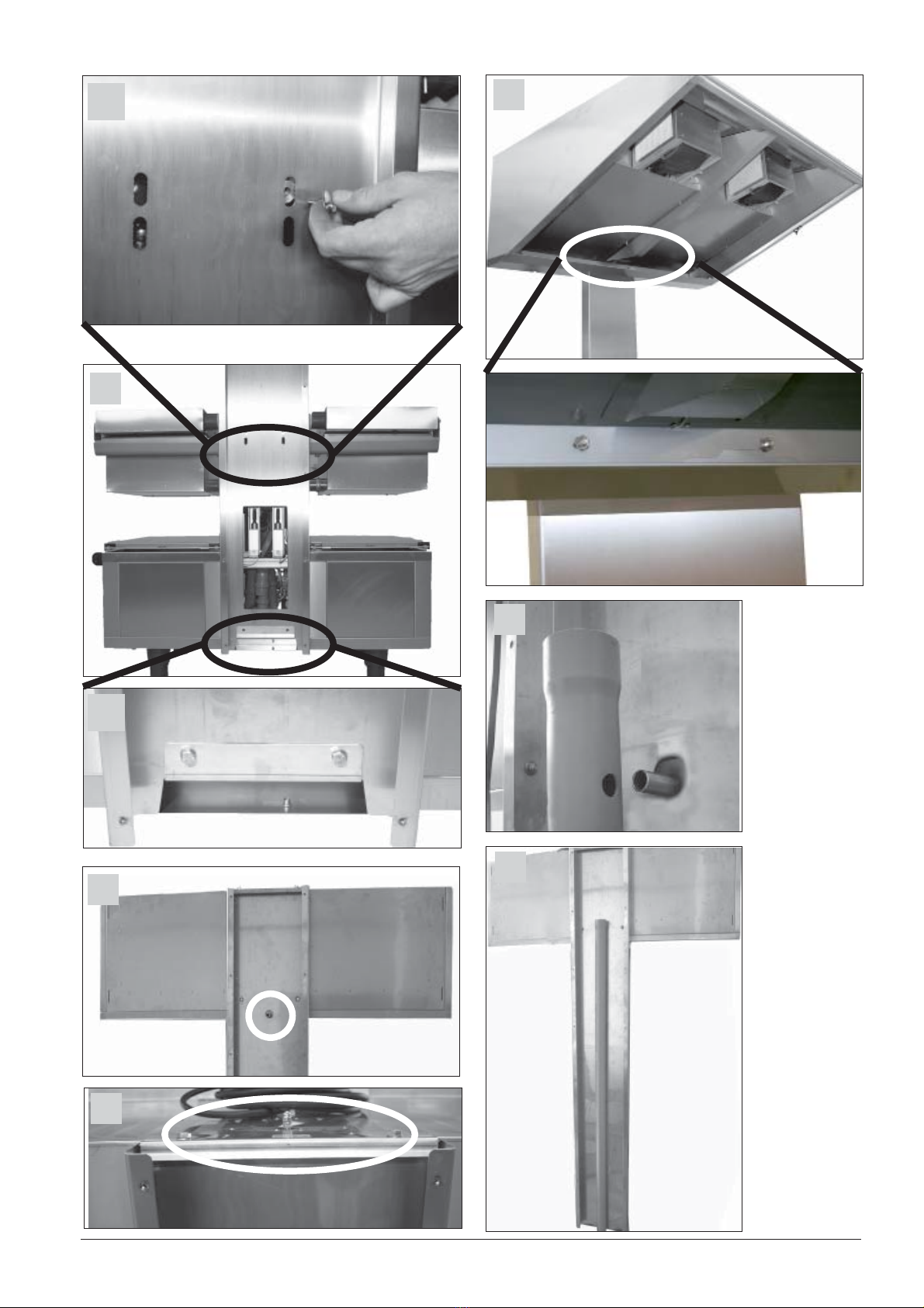
- Démonter la façade de commande.
- Retirer la paroi arrière du
VarioCooking Center®Fig. 3
Valable pour VarioCooking Center®
avec numéro de série E11VA…
- Introduire de l‘intérieur du châssis 2 vis
M8x35 à rondelle dans le cadre et visser
à l‘extérieur les écrous (pièce 7) Fig. 3B
Valable pour tous les VarioCooking
Center®
- Desserrer les 2 écrous M8 et l’écrou M5
à l’arrière du châssis. Fig. 3 A
- Placer le profil porteur de la plaque de
retenue (pièce 3) sur les 3 boulons file-
tés et la fixer avec les 3 écrous
combi retirés auparavant. Fig. 3 A
Valable pour VarioCooking Center®
avec numéro de série E11VA…
- Placer le profil porteur (pièce 1) en bas
sur la plaque de retenue (le profil por-
teur doit être derrière l’arête) Fig. 4 B
- Ensuite, basculer le profil porteur contre
le bâti de l’appareil et visser à fond avec
les 2 rondelles et les 2 écrous sur les
vis M8x35 avec l‘entretoise déjà fixée
Fig. 4A
- Le fixer ensuite en bas avec 2 vis
M8x16 et 2 rondelles sur la plaque de
retenue Fig. 4 B
Valable pour VarioCooking Center®à
partir des numéro de série E11VB… ou
E11PB…
- Placer le profil porteur (pièce 1) en bas
sur la plaque de retenue (le profil por-
teur doit être derrière l’arête) Fig. 5 B
- Ensuite, basculer le profil porteur contre
le bâti de l’appareil. D‘une main, posi-
tionner l‘entretoise alu et de l‘autre
visser une vis M6x20 avec une rondelle
large dans le châssis au travers de l‘en-
tretoise. Visser légèrement la première
vis puis recommencer l‘opération avec
la seconde vis. Puis serrer les deux vis.
Fig. 5A

- 13 -
V 05 F
- Le fixer ensuite en bas avec 2 vis
M8x16 et 2 rondelles sur la plaque de
retenue Fig. 5 B
- Soulever la hotte (pièce 8) à deux et la
maintenir par devant contre le profil por-
teur.
- Introduire d’abord le tube de sortie dans
le trou du profil porteur Fig. 6
- Continuer à soulever la hotte et pousser
l’arête supérieure vers l’arrière jusqu’à
ce que l’arête de la hotte s’enclenche
sur le profil porteur. On peut alors lâcher
la hotte car elle est déjà suspendue en
toute sécurité. Ensuite, visser la hotte
en haut sur le profil porteur avec 2 vis
M8x16 et 2 rondelles Fig. 7
- Puis, visser aussi la hotte sur le profil
porteur avec 2 vis M8x16 et des rondel-
les dans la section inférieure de la hotte.
Introduire les vis dans la hotte par
l’arrière du support profilé et les
visser. Fig. 8
- Vérifier le tuyau d’évacuation de la
hotte. Ce tuyau doit être légèrement
incliné vers le bas ; si ce n’est pas le
cas, le faire pencher vers le bas en lui
donnant un petit coup. Fig. 9
- Placer le tuyau HT (pièce 4) sur le tuyau
d’écoulement, puis fermer le tuyau HT
(pièce 5) avec le couvercle Fig. 9/10
- Poser le couvercle du profil porteur
(pièce 2) à l’arrière sur le profil porteur
et le visser avec les vis à tête bombée
- Raccorder l’écoulement d’eau au tuyau
HT
3. Raccordement électrique de la hotte
Danger !
Lors de l‘installation s‘assurer que la
source d‘alimentation est bien celle
demandée.
- Raccordement électrique: La hotte doit
être raccordée à une alimentation élec-
trique conforme aux normes en vigueur
(prescriptions VDE). Avant de retirer le
câble de connexion au secteur ou de le
reconnecter au secteur, veuillez vous
assurer que la hotte est éteinte.
Attention!
Tenir compte des codes de couleur des
fils. Un raccordement incorrect peut
entraîner une décharge électrique.
Attention:
Un raccordement incorrect peut entraîner
des dommages sur l‘appareil .
- La fiche de secteur doit être accessible,
sinon il faut avoir installé un dispositif de
séparation sur tous les pôles avec un
écartement des contacts de 3 mm mini-
mum.
- Raccordez la Ultravent®à des prises de
sécurité usuelles avec une protection
par fusibles de 16 A. La hotte est équi-
pée d’un câble de raccordement de 2 m
environ avec une fiche.
- S’il faut remplacer un jour le câble de
raccordement, utiliser au moins un câble
de qualité H05 RN-F 3x2,5 mm².
- Dans la partie supérieure des appa-
reils se trouve le branchement pour la
liaison équipotentielle. Connectez-le au
conducteur d’équipotentialité.

- 14 - V 05
D
Sicherheitshinweise
Gefahr!
Unmittelbar gefährliche
Situation, die schwerste
Verletzungen oder Tod zur
Folge haben kann.
Ätzende Stoffe
Achtung: Nichtbeachtung
kann Materialschäden zur
Folge haben.
Warnung!
Möglicherweise
gefährliche Situation, die
möglicherweise schwere
Verletzungen oder Tod zur
Folge haben kann.
Brandgefahr!
Tipps und Tricks für die
Installation.
Vorsicht!
Möglicherweise gefährliche
Situation, die leichte
Verletzungen zur Folge
haben kann.
Verbrennungsgefahr!
Gefahr!
Hochspannung.
Vorsicht Lebensgefahr
Nichtbeachtung kann
schwerste Verletzungen
oder Tod zur Folge haben.
Piktogrammerklärung

- 15 -
V 05 D
Warnung:
Eine falsche Installation, Einstellung, Service oder Wartung, sowie Veränderungen am
Gerät können zu Beschädigungen, Verletzungen oder zum Tod führen. Lesen Sie das
Bedienhandbuch sorgfältig durch bevor Sie das Gerät in Betrieb nehmen.
Folgende Sicherheitshinweise sind zu beachten:
Gültige Norm: EN 60335-2-99
- Es muss für eine ausreichende Belüftung des Raumes gesorgt werden, wenn die
UltraVent®Kondensationshaube gleichzeitig mit Geräten benutzt wird, die Gas oder
andere Brennstoffe verbrennen.
- Es darf nicht unter der Haube flambiert werden.
- Vorschriften hinsichtlich der Belüftung und Ableitung der Abluft sind einzuhalten
- besondere Aufmerksamkeit ist notwendig, wenn in demselben Raum andere Geräte
mit offenem Abzug sind um ein Rücksaugen der Abgase zu verhindern.
- Die Verwendung dieser Ultravent®ersetzt nicht die vorgeschrieben Abgasabfuhr über
eine separate Abgashaube, Lüftungsdecke oder Kamin.
- Wenn die Abgasabführung eines Gasgerätes über eine Abgashaube bzw.
Lüftungsdecke erfolgt, muss gemäß den nationalen Gasvorschriften eine nicht selbst-
tätig rückstellende Einrichtung angebracht sein, die die Gaszufuhr zum Gerät abstellt
wenn die Abluftanlage aufhört zu arbeiten.
- Die Anbringung der Ultravent®darf nicht gegen Gasvorschriften verstoßen.
Achtung!
Schäden auf Grund Nichtbeachtung dieser Installationsvorschrift sind von der Garantie
ausgeschlossen.
Die erforderlichen Anschlüsse (Wasser, Elektro und Gas) dürfen nur von geeignetem
Fachpersonal gemäß den örtlichen Bestimmungen durchgeführt werden.
Bei Normalbetrieb liegt der Geräuschpegel des Gerätes unter 70 dB(A)
Entsorgung Altgeräte
Das Gerät darf nach Ende seiner Lebenszeit nicht in den Müll und auch nicht in die
Altgerätecontainer bei den kommunalen Sammelstellen abgegeben werden.
Gerne sind wir bei der Entsorgung des Gerätes behilflich.
Überprüfung nach Transport
Gerät auf Transportschäden überprüfen.
Bei Verdacht auf Transportschäden unverzüglich Ihren Fachhändler / Spediteur benach-
richtigen!
Alle Kartons, Verpackungsmaterialien, Dokumente, etc. aus dem Garraum entfernen.

- 16 - V 05
D
Sehr geehrter Kunde,
wir bitten Sie, die vorliegende
Bedienungsanleitung sorgfältig durchzule-
sen. Schäden auf Grund Nichtbeachtung
dieser Installationsvorschrift sind von der
Garantie und Haftung ausgeschlossen.
Ultravent®komplett 60.70.804
Teile Bild 1
Pos. Bezeichnung Artikel Nummer
1 Tragprofil 36.003.686
2 Deckel Tragprofil 36.003.685
3 Halteblech Tragprofil 36.003.699
4 HT-Rohr 60.70.896
5 Deckel HT-Rohr 2070.0053
6 Distanzscheibe 10.00.762
7 Abstandshalter 10.00.761
Teil Bild 2
Pos. Bezeichnung
8 Ultravent®60.70.891
Installation
1. Anlieferung
Packen Sie das gelieferte Gerät sorgfäl-
tig aus und vergewissern Sie sich, daß
auf dem Transport keine Schäden ent-
standen sind.
2. Installation
- Rückwand des VarioCooking Center®
entfernen Bild 3
Vorsicht
Beachten Sie das Gewicht der Geräte.
Benutzen Sie Tragehilfen.
Netto Gewicht:
Ultravent®112 145 kg
Ultravent®211 153 kg
Ultravent®311 246 kg
Gültig für VarioCooking Center®mit
Seriennummer E11VA.....
- 2 Schrauben M8x35 mit Unterlegschei-
ben von innen durch den Grundrahmen
des VarioCooking Center®stecken und
außen mit den Abstandshaltern
(Teil 7 SW 17) verschrauben Bild 3 B
Gültig für alle VarioCooking Center®
- Die 3 Muttern im Boden des
VarioCooking Center®lösen Bild 3 A
- Halteblech Tragprofil (Teil 3) über die
3 Gewinde-Bolzen setzten und mit den
zuvor entfernten 3 Combi-Mutter wieder
anziehen Bild 3A
Gültig für VarioCooking Center®mit
Seriennummer E11VA.....
- Tragprofil (Teil1) unten auf das Halte-
blech einsetzten (Tragprofil muss hinter
die Umkantung) Bild 4 B
- Anschließend Tragprofil gegen den
Grundrahmen kippen und mit 2 Unter-
legscheiben und 2 Muttern auf den
M8x35 Schrauben mit den bereits
befestigten Distanzhülsen festschrau-
ben. Bild 4A
- Anschließend unten mit 2 Schrauben
M8x16 und 2 Unterlegscheiben an dem
Halteblech befestigen Bild 4 B
Gültig für VarioCooking Center®ab
Seriennummer E11VB....oder E11PB
- Tragprofil (Teil1) unten auf das Halte-
blech einsetzten (Tragprofil muss hinter
die Umkantung) Bild 5 B
- Anschließend das Tragprofil gegen
den Grundrahmen kippen. Mit einer
Hand das runde Distanzstück (Teil 6)
zwischen Grundrahmen und Tragprofil
schieben und mit der anderen Hand
eine Schraube M6x20 mit großer
Unterlegscheibe durch das Tragprofil
und das Distanzstück im Grundrahmen
verschrauben. Die Schraube nur
leicht anziehen und die Prozedur
mit dem zweiten Loch wiederholen.

- 17 -
V 05
Anschließend beide Schrauben
anziehen. Bild 5 A
- Anschließend unten mit 2 Schrauben
M8x16 und 2 Unterlegscheiben an dem
Halteblech befestigen Bild 5 B
- Zu zweit die Ultravent®(Teil 8) hoch-
heben und von vorne an das Tragprofil
halten.
- Zu erst das Auslaufrohr der Ultravent®in
das Loch des Tragprofil einführen
Bild 6
- Ultravent®weiter anheben und obere
Kante nach hinten drücken, bis die
Umkantung der Ultravent®über das
Tragprofil einrastet.
Danach kann man die Ultravent®
loslassen, sie hängt bereits
sicher. Anschließend Ultravent®
mit 2 Schrauben M8x16 und 2
Unterlegscheiben am Tragprofil
oben anschrauben Bild 7
- Zusätzlich Ultravent®ebenfalls mit 2
Schrauben M8x16 und Unterlegscheiben
an den Tragprofilen am unteren Bereich
der Ultravent®anschrauben. Die Schrau-
ben von hinten durch das Tragprofil
stecken
und verschrauben. Bild 8
- Ablaufrohr der Ultravent®überprüfen.
Das Rohr muss leicht nach unten
geneigt sein, ist dies nicht der Fall, dann
das Rohr mit einem leichten Schlag
nach
unten biegen Bild 9
- HT-Rohr (Teil 4) auf das Ablaufrohr ste-
cken und anschließend mit dem Deckel
HT-Rohr (Teil 5) verschließen Bild 9/10
- Deckel Tragprofil (Teil 2) von hinten auf
das Tragprofil setzten und mit Becher-
schrauben verschrauben
- Wasserablauf an das HT-Rohr anschlie-
ßen
3. Elektrischer Anschluß der
Ultravent®
Gefahr!
Hochspannung
Beachten Sie die Vorschriften der örtlichen
Energie-Versorgungs-Unternehmen bei
der Installation!
- Die Ultravent®muss an ein genormtes
Versorgungsnetz gemäß der gültigen
Vorschriften angeschlossen sein. (VDE
Vorschriften). Vor dem Ziehen des
Netzsteckers oder dem Wiederanschluß
ans Netz achten Sie bitte darauf, daß
die Ultravent®ausgeschaltet ist.
Warnung
Farbkodierung der Adern beachten.
Falscher Anschluss kann zu Stromschlag
führen
Achtung
Falscher Anschluss kann zu
Beschädigungen am Gerät führen
- Der Netzstecker muss zugänglich
sein, ansonsten muss eine allpolige
Trennvorrichtung mit mindestens 3 mm
Kontaktabstand vorhanden sein.
- Schließen Sie die Ultravent®an
übliche Sicherheitssteckdosen mit 16 A
Absicherung an. Die Ultravent®ist mit
einer ca. 5 m langen Anschlussleitung
mit Stecker ausgestattet.
- Sollte im Ersatzteilfall die
Anschlussleitung ausgetauscht werden
müssen, ist mindestens eine Leitung
der Qualität H05 RN-F 3x1,5 mm2zu
nutzen.
- An der Oberseite der Ultravent®
befindet sich der Anschluß für den
Potentialausgleich. Verbinden Sie die-
sen mit dem Potentialausgleichsleiter.
D
- 18 - V 05
GB
Safety instructions
Danger!
Immediate dangerous
situation, that can endanger
severe injury or death
Corrosive substances
Attention: Inobservance
can cause material
damages.
Warning!
Possibly dangerous
situation, that possibly can
endanger severe injury or
death.
Fire hazard!
Tips and tricks for
installation
Attention!
Possibly dangerous
situation, that can endanger
minor injury.
Danger of burning!
High voltage.
Caution danger of life
Inobservance can endanger
severe injury or death.
Explanation of the icons
- 19 -
V 05 GB
Warning
Incorrect installation, adjustment, alteration, service or maintenance can cause property
damage, injury or death. Read the installation operating and maintenance instructions
thoroughly before installing or servicing this equipment.
The following safety instructions must be observed:
- It must be ensured that there is sufficient room ventilation, when the Ultravent®runs
simultaneously with units that burn gas or other combustibles.
- It is not allowed to flambé underneath the hood.
- National standards concerning ventilation and exhaust air must be observed.
- If there are other appliances with an open escape in the same room it has to be made
sure that a back draw of flue gases will be prevented.
- The installation of this Ultravent®does not substitute a mandatory flue gas evacuation
via a separate exhaust hood, ventilated ceiling or chimney
- If the flue gas evacuation is done by means of an extraction hood or ventilated ceiling
an independent appliance must be installed that interrupts the gas supply to the unit if
the exhaust air appliance stops working.
- The installation of the Ultravent®must not offend against gas standards.
Attention
Damages based on installation not complying with the directives given hereunder are not
covered by warranty terms.
The requisite connections (water and electricity) must only be carried out by suitably
qualified technicians in compliance with local regulations.
In normal mode, the noise level of the unit is less than 70 dB(A).
Dumping of old units.
At the end of its service life, the unit must not be disposed of with the general waste and
must not be placed in the recycling containers at local authority collection points.
We will be happy to help you with the disposal of your unit.
Check after shipping
Check for any transport damage.
Should there be any signs of transport damage, inform your dealer/freight forwarder
immediately! Remove all cartons, packing materials, documents, etc. from the interior
cabinet.
- 20 - V 05
GB
Dear customer,
please read this installation manual care-
fully before installing the Ultravent®.
Damages based on installation not comply-
ing with the directives given hereunder are
not covered by warranty terms..
Ultravent®complete 60.70.804
Parts picture 1
Pos. Description Art. Number
1 Supporting channel 36.003.686
2 Cover panel 36.003.685
3 Support bracket 36.003.699
4 HT-Pipe 60.70.896
5 Lid HT-pipe 2070.0053
6 Spacer disc 10.00.762
7 Spacer nut 10.00.761
Parts picture 2
Pos. Description
8 Ultravent®60.70.891
Installation
1. Delivery
Carefully unpack the unit on delivery
and check to ensure that no damage
has been caused in transit (follow the
instructions on the packaging).
2. Installation
Attention
Observe the weight of the units.
Use carrying aid to avoid injuries.
Net weight:
Ultravent®112 145 kg
Ultravent®211 153 kg
Ultravent®311 246 kg
- Remove rear panel of VarioCooking
Center®. pic. 3
Only valid for VarioCooking Center®
with serial number E11VA....
- Stick 2 screws M8x35 with washers into
the holes of the base frame of the unit
and tighten them with the spacer nut
(Item 7) using spanner 17 mm pic. 3 B
Valid for all VarioCooking Center®
- Loosen the three nuts in the bottom
frame of VarioCooking Center®. pic. 3 A
- Put the support bracket (item 3) over the
3 studs and fix it with the previous remo-
ved combi nuts. pic. A
Only valid for VarioCooking Center®
with serial number E11VA...
- Put the supporting channel (item 1) on
to the support bracket.
Supporting channel must be standing in
the inner side of the bracket. pic 4 B
- Then hold the supporting channel
against the frame with the hex spacers
- Fix the channel with two nuts and
washers to the screws facing through
the spacers. pic. 4 A
- Next fix the channel to the support bra-
cket using two screws M8x16 and
2 washer pic 4 B
Only valid for VarioCooking Center®as
of serial number E11VB...or E11PB...
- Put the supporting channel (item 1) on
to the support bracket.
Supporting channel must be standing in
the inner side of the bracket. pic 5 B
- Afterwards press supporting channel
against the unit frame. Insert spacer
disc (item 6) by sticking the hand in the
opening of the supporting channel and
putting the disc between channel and
unit frame. With the other hand fix the
screw (M6x20) to the selected hole. Pull
screw only hand tight. Repeat the
procedure at the other hole. pic. 5A
Table of contents
Languages:
Other TOPINOX Commercial Food Equipment manuals


Popular Commercial Food Equipment manuals by other brands


Rühle
Rühle MPR 150 Translation of the original instructions

Buffalo
Buffalo CU489 instruction manual

Salvis
Salvis Smartline SILOFRIT Series installation instructions

Bartscher
Bartscher SNACK A162.402E instruction manual

Bonnet Neve
Bonnet Neve COLISEUM 4 ECO User instructions

Polar Electro
Polar Electro UA013-A instruction manual