Einbaubeschrieb
ACHTUNG: Das Gerät darf nicht in
eine brennbare Umgebung eingebaut
werden.
Die Geräte können in CNS- oder
Steinabdeckungen bis 40 mm Dicke
eingebaut werden.
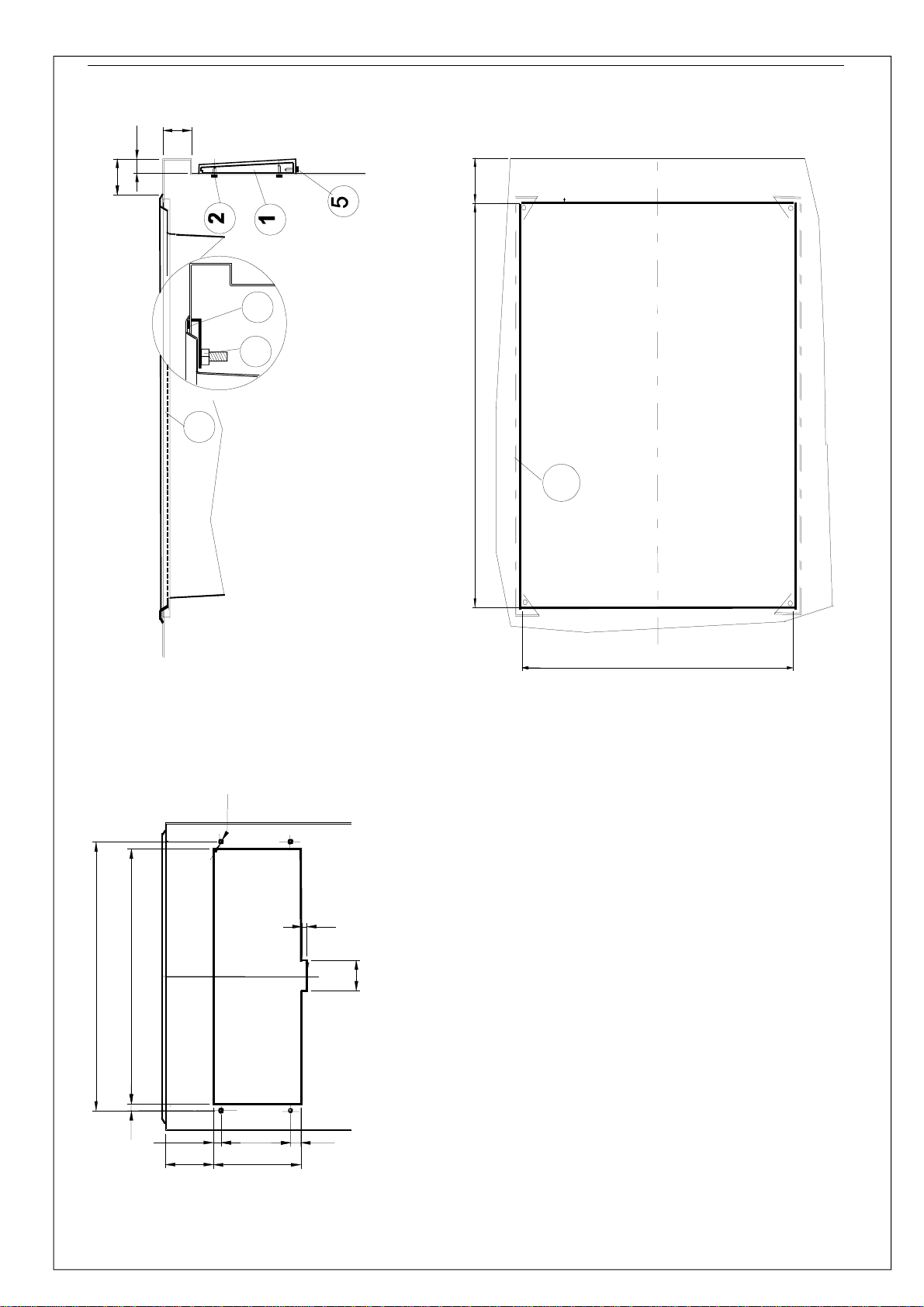
Beim Einbau ist wie folgt vorzugehen:
1. Nach Zeichnung, Einbauöffnungen
ausschneiden und Befestigungslö-
cher bohren.
2. Instrumentenschild erst durch die
grosse, dann durch die kleine
Öffnung nach aussen führen.
3. Die zwei lose mitgelieferten Sei-
tenpfosten (1) auf der Front posi-
tionieren und von innen mit den 4
beiliegenden Schrauben (2) befe-
stigen.
4. Becken umgekehrt auf den Tisch
legen. Im Auflageprofil zum Ab-
dichten genügend hitzebeständi-
ges Silikon oder Pactan (3) anbrin-
gen.
5. Becken in Ausschnitt einbauen.
6. Die 2 beiliegenden Verstärkungs-
schienen (6) über die Befesti-
gungsbolzen legen. Dann mit bei-
liegenden 6-kt Muttern (4) befesti-
gen.
7. Instrumentenschild an die zwei
Seitenpfosten montieren. Zuerst
oben, dann unten einhängen und
anschrauben (5).
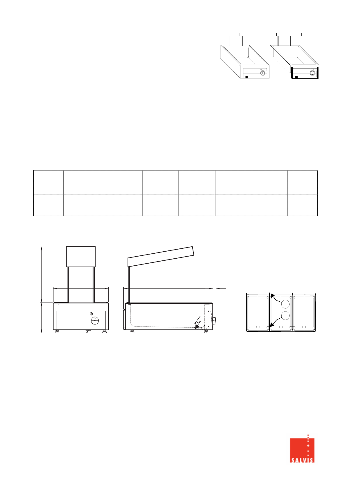
Elektroanschluss
- Angaben auf dem Typenschild
beachten. Beim Tischgerät befin-
det es sich auf dem Aussenman-
tel. Beim Einbaugerät auf der In-
nenseite des Instrumentenschil-
des.
- DIE GERÄTE DÜRFEN NUR VON
AUTORISIERTEN ELEKTRO-
INSTALLATEURENANGE-
SCHLOSSEN WERDEN !
- Die landesspezifischen und örtli-
chen Vorschriften müssen einge-
halten werden.
- Das Tischgerät wird mit 1.8 m
Kabel ohne Stecker geliefert. Mon-
tage eines Netzsteckers undAn-
schluss über eine Steckdose oder
Anschluss an einen Hauptschalter
für allpolige Trennung mit einer
Kontaktöffnung von min. 3 mm.
- Steckdose in der Nähe des Gerä-
tes plazieren. Der Stecker muss
gut zugänglich sein.
Description of installation
ATTENTION:
The unit must not be installed in a
flammable environment.
Units can be installed in stainless
steel or stone covering up to 40 mm
thickness.
Proceed as follows for installation:
1. Cut out installation openings ac-
cording to the drawing and drill
fixing holes.
2. Pass the instrument panel first
through the large opening and
then through the small opening to
the outside.
3. Position the two separately supp-
lied side posts (1) at the front and
fix from inside with the 4 screws
(2) supplied.
4. Place the tank upside down on the
table. Place sufficient heat-resi-
stant silicone or Pactan (3) in the
support profile.
5. Mount tank into opening.
6. Place 2 supplied reinforcing rails
(6) over the fixing bolts and then
fix with hexagon nuts (4).
7. Mount the instrument panel on the
two side posts. First suspend from
the top and then screw on (5).
Electrical connection
- Note the information on the rating
plate. In the case of a table top
unit, it is present on the outer jak-
ket. In the case of a built-in unit, it
is present on the inside of the
instrument panel.
- THE UNITS MAY BE CONNEC-
TED ONLY BYAUTHORIZED
ELECTRICALFITTERS!
- The national and local regulations
must be observed.
- The table-top unit is supplied with
a 1.8 m cable without a plug.
Mount a mains plug and connect
via a socket or connection to a
main switch for all-pole isolation
with a contact opening of min.
3 mm.
- Position the socket in the vicinity
of the unit. The plug must be easi-
ly accessible.
Description du montage
ATTENTION: L’appareil ne doit pas
être encastré dans un environnement
combustible.
L’installation des appareils peut être
effectué dans des recouvrements en
Inox ou en pierre épaisseur max.
40 mm.
Pour le montage, procéder de la ma-
nière suivante:
1. Découper les ouvertures
d’encastrement et percer les trous
de fixation selon le dessin.
2. Passer la plaque de l’instrument
d’abord par la grande ouverture,
puis par la petite.
3. Positionner les deux piliers la-
téraux (1) livrés séparément sur la
face et les fixer depuis l’intérieur
avec les 4 vis jointes (2).
4. Poser le bassin renversé sur la
table.Appliquer dans le profil d’ap-
pui suffisamment de Silicone rési-
stant à la chaleur ou de Pactan
(3).
5. Installer le bassin dans la décou-
pure.
6. Poser les 2 rails de renforts (6)
joints sur les boulons de fixation
puis les fixer avec les écrous he-
xagonaux (4).
7. Monter la plaque d’instruments sur
les deux piliers latéraux. Suspend-
re d’abord en haut, puis en bas (5)
et visser.
Raccordement électrique
- Observer les indications sur la
plaquette signalétique. Sur
l’appareil de table, elle se trouve
sur le manteau extérieur. Sur
l’appareil encastré, à l’intérieur de
la plaque d’instruments.
- LESAPPAREILS NE DOIVENT
ETRE RACCORDES QUE PAR
UN INSTALLATEUR ELECTRICI-
ENAUTORISE !
- Les prescriptions nationales et
locales en vigueur doivent être
respectées.
- L’appareil de table est livré avec
1,8 m de câble, sans fiche. Monta-
ge d’une fiche de réseau et rac-
cordement par une prise ou rac-
cordement à un interrupteur princi-
pal pour séparation omnipolaire
avec une ouverture de contact de
3 mm au moins.
- Placer la prise à proximité de
l’appareil. La fiche doit être bien
accessible.