Topology DS102 User manual

浙江图谱智能科技有限公司
WWW.TOPOLOGY-TECH.COM
文件编号 TOP-DS102 -U-01-1.0
版本号 1.0
DS102 Display technical specifications
Product Name:Intelligent LCD display
Part Number:DS102
Zhejiang Topology Intelligent Technology Co., Ltd WWW.TOPOLOGY-TECH.COM
Room 702,Tower A, DIC, No.1190 Bin’an Rd. Hangzhou, Zhejiang
TEL: 0571-87633029
Signature Date
Write
Checked by
Approved by

第2页/共17 页
Content
A. Product introduce .......................................................................................................... 4
1 Product name and model .............................................................................................. 4
2 Product Introduction ....................................................................................................... 4
3 Range of application ....................................................................................................... 4
4 Appearance and size ....................................................................................................... 4
5 Display coding rules......................................................................................................... 5
B. Product manual .............................................................................................................. 6
1. Specifications ............................................................................................................... 6
2 Functional overview ......................................................................................................... 6
3 Installation .......................................................................................................................... 7
4 Interface .............................................................................................................................. 8
5 Definition of the buttons ................................................................................................ 9
6 Operation ........................................................................................................................... 9
6.1 Turn on/off .............................................................................................................. 9
6.2 Assist mode select .............................................................................................. 10
6.3 Display information switch ............................................................................... 10
6.4 Walk assist mode ................................................................................................ 11
6.5 Headlight (backlight) on/off............................................................................. 12
6.6 Power indicator ................................................................................................... 12
7 User settings ................................................................................................................... 13
7.1 enter setting......................................................................................................... 13
7.2 unit setting ........................................................................................................... 13

第3页/共17 页
7.3wheel diameter information .............................................................................. 14
7.4 Speed limitation information ........................................................................... 14
8.Data clearance ............................................................................................................... 15
9 Error information ........................................................................................................... 15
9.1 error shown ......................................................................................................... 15
9.2 error code definition .......................................................................................... 16
10 wire definition .............................................................................................................. 16
C. Note ............................................................................................................................... 16

第4页/共17 页
Intelligent LCD display, model:DS102
²Simple and lightweight, separate installation bracket design
²High contrast 3.5 inch segment LCD screen
²Excellent outdoor design with IPx5 level waterproof
²Micro USB serial communication interface, convenient maintenance services
Suitable for electric power assist bicyclein accordance with the standard of EN15194
The material of product shell is ABS + PC. And the material of the window is tempered glass.

第5页/共17 页
4.1 Switch appearance and dimensions
4.2Display appearance and dimensions
As shown as above picture, C1 is the manufacture factory code
1701 is the manufacture year and week number;
第6页/共17 页
A means the hardware version;
001 is the firmware version number
0001 is the product serial number
1. Specifications
①Power supply:DC 24V/36V/48V
②Rated current:18mA/36V
③Shutdown leakage current:<1uA;
④Screen specification:3.5” LCD(FSTN)
⑤Communication method:UART
⑥Operating temperature:-20°C ~ 60°C
⑦Storage temperature:-30°C ~ 80°C
⑧Waterproof level:IP65
①Four buttons, easy to operate
②Km / miles
③ Mileage display: Subtotal mileage (TRIP), total mileage (ODO)
④Speed display: Real-time speed(SPEED)、maximum speed(MAX)、average speed(AVG)
⑤Five stalls of power assist control:0-4level (OFF-ECO-TOUR-SPORT-TURBO)
⑥Six levels of electricity instructions:1-5level power,and under voltage prompts
⑦Headlight indicator: Headlight on/off status indication (need information from controller)
⑧Motor power display: Realtime display motor output power (segment display)
⑨Riding time (TRIP TIME)display
⑩6km/h walk assist function
⑪System maintenance instructions: Advice maintenance information based on riding distance
and charge cycles
⑫UART communication port(Micro USB),convenient for system maintenance, parameter setting.
第7页/共17 页
⑬ Error code indicator
①Determine if you need to select the corresponding mounting clamp and rubber clip ring according
to the diameter of the handle bar(Applicable handle bar specifications:Φ22.2、Φ25.4、Φ31.8).
Open the display lock clamp and insert the rubber clip into the correct position of the lock clamp.
②Set the rubber ring in the bracket then assembleon the middle of the handle bar, adjust the angle of
the display,make it easier to see the display screen when riding. After fixing the angle, tighten the
screws. Tightening torque is 1N.m.
③Open the lock ring of the switch and set it in the prorate position on the left side of the handlebar.
Adjust the angle of the switch, so that rider can see the switch and operate easily. (Applicable handle
bar dimensionis Φ22.2)
④Fix and tighten the handlebar fixing screw with M3Hex wrench, locking torque is 0.8Nm.
⑤Connect the display connector to the controller connector according to the label.
Note: Damage caused by excessive torque is not covered by the warranty.
第8页/共17 页
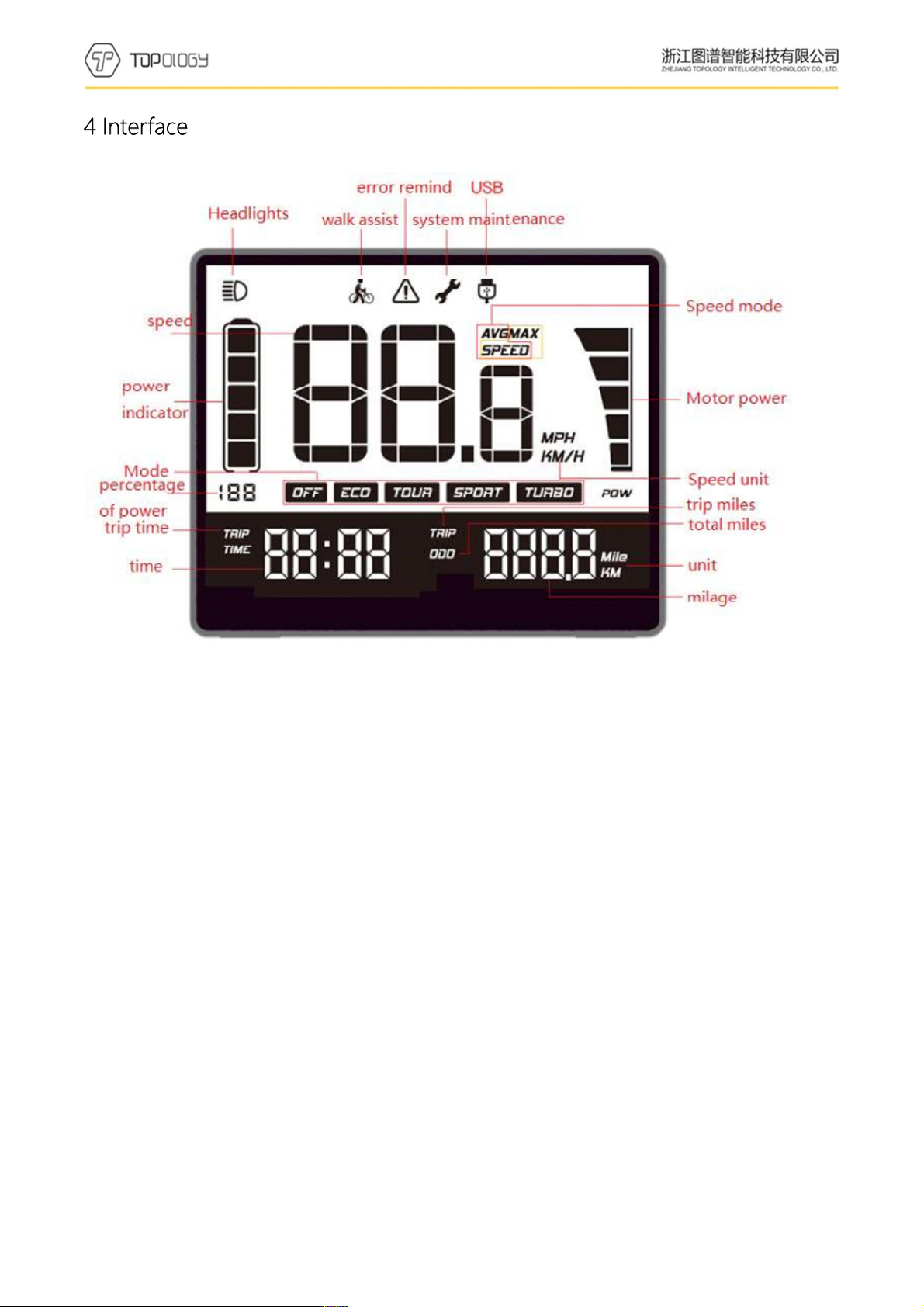
①Headlights:It shows when the headlamp is on. When the headlamp is turned off or does not have
this function. The icon is not showed.
②Walk assist:It shows when 6KM walk assist mode. It is not showed on the rest of the states.
③Error remind:This icon flashes when the system is malfunction.It will not be seen when normal
use.
④System maintenance:It shows when the system needs to be maintained(It shows when the mileage
exceeds the set value or the number of battery cycles reaches the set value. If the customer does not
request, it closed and was not shown as default.)
⑤USB:It shows when the display communicates with the PC, It is not showed on the rest of the
states.
⑥Speed:When the display turned on, it shows the speed.
⑦ speed mode:SPEED indicates that the speed shown on the display is the current speed, AVG
SPEED indicates that the speed shown is the average speed,MAX SPEEDindicates that the speed
shown is the maximum speed.
第9页/共17 页
⑧ power indicator: Five levels power indicate and under voltage indicate.
⑨ Percentage of power: Indicate the percentage of the battery power.
⑩ Mode:Shows the current assist mode, range from low power assist to high power assist: ECO、
TOUR、SPORT、TURBO, ECO as default;OFF indicate no power assist.
⑪ Speed unit: indicate the unit of the speed, KM/H or MPH.
⑫ Motor power: it has five sections to show motor real-time power.
⑬Trip time: It shows the ridding time of the trip.
⑭Time: it shows the riding time including hours and minutes
⑮trip miles: When this icon is on, the number after the icon means the mileage of each trip,
unit can be mile or Km.
⑯ODO:When this icon is on, the number after the icon means the mileage of all trips; unit can
be mils or Km.
⑰unit:It’s the unit of trip mileage and total mileage, with Mile and KM 2 options.
⑱Mileage: It shows the number of the mileage. Trip mileage is accurate to one decimal place,
the total mileage is accurate to single digits.
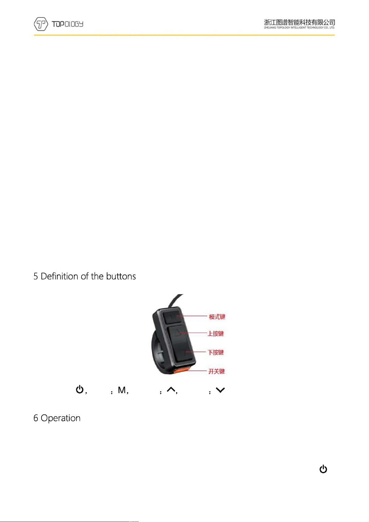
On/off:Mode Adjust+ Adjust -
6.1 Turn on/off
Maintain the normal connection of the display and the controller. Long press (2 seconds) 键
button when is display is off.Display shows the boot interface with all icons on. Then it enters the
第10 页/共17 页
basic interface to start work. Long press (2 seconds) button when is display is on. Display closed.
If no operation to the display and the speed is 0 for 5 minutes, display will turn off automatically.
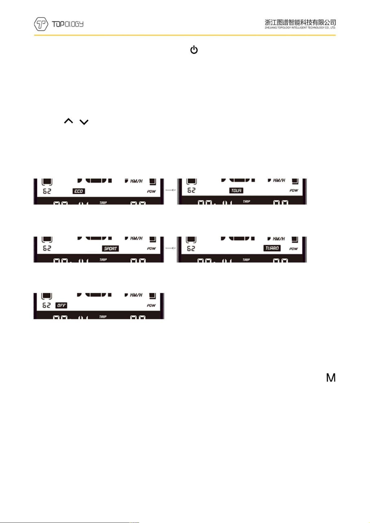
6.2Assist mode select
Press or to select the assist mode and change the assist power mode. There are 5 modes:
OFF/ECO/TOUR/SPORT/TURBO. Default ECO mode when display turned on. OFF means no
assist power.(assist mode select as below picture)
ECO Mode TOUR Mode
SPORT Mode TURBO Mode
OFF Mode
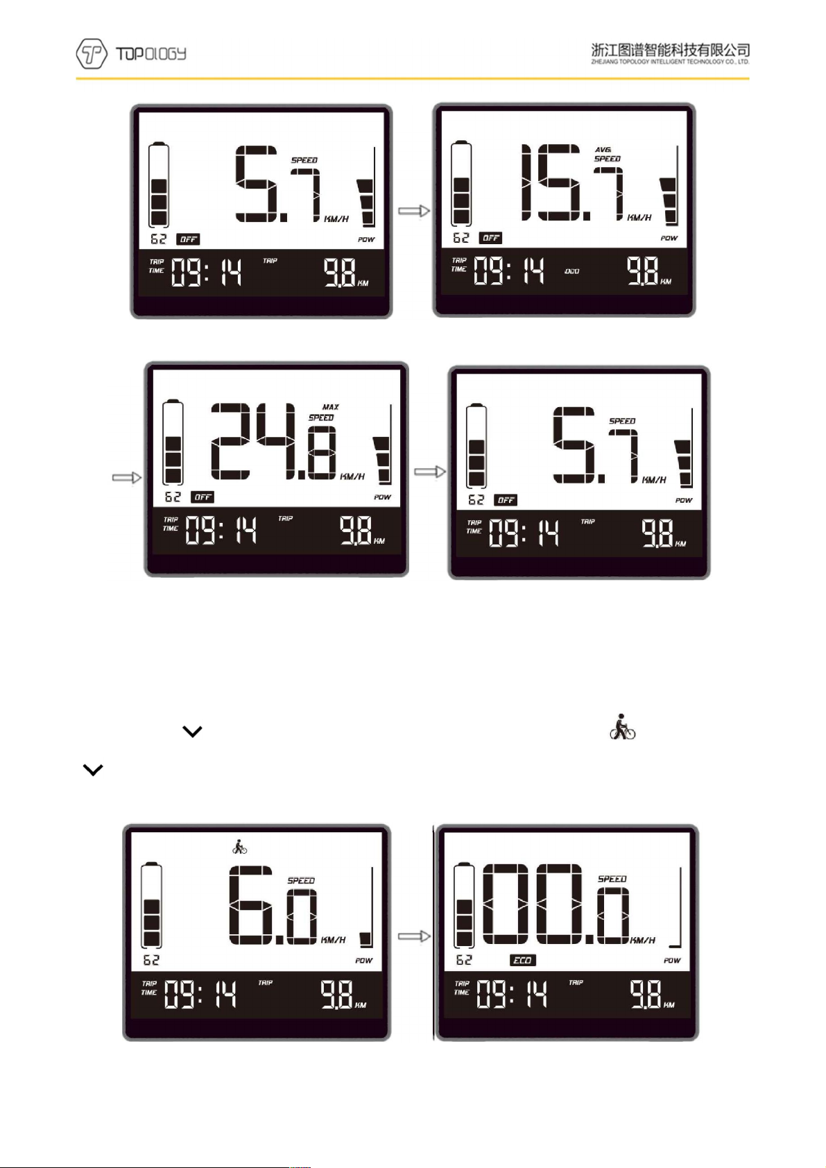
6.3 Display information switch
Information switches from trip miles, average speed, max speed, total mileage by short press
when the display is on. It shows loop from current speed/trip miles (TRIP) -> average speed (AVG)、
total mileage (ODO)->maximum speed (MAX)、trip miles (TRIP)->current speed/trip miles (TRIP).
Mode switch as below pictures:
第11 页/共17 页
SPEED、TRIPAVG SPEED、ODO
MAX SPEED、TRIP SPEED、TRIP
6.4Walk assist mode
Long press button for 2 seconds, bike entered walk assist mode. When is shown, loose
button to exit walk assist mode .Walk assist mode switch as below pictures (only in the walk
assist status):
Walk assist Mode Normal Mode
第12 页/共17 页
6.5Headlight (backlight) on/off
Long press button for 1 second,the headlight is turned on(need support of controller).Headlight
icon shows on the interface. At the same time, the backlight is on. Long press button for 1
second again, the headlight is turned off. The icon of headlight is off. And the backlight is off.
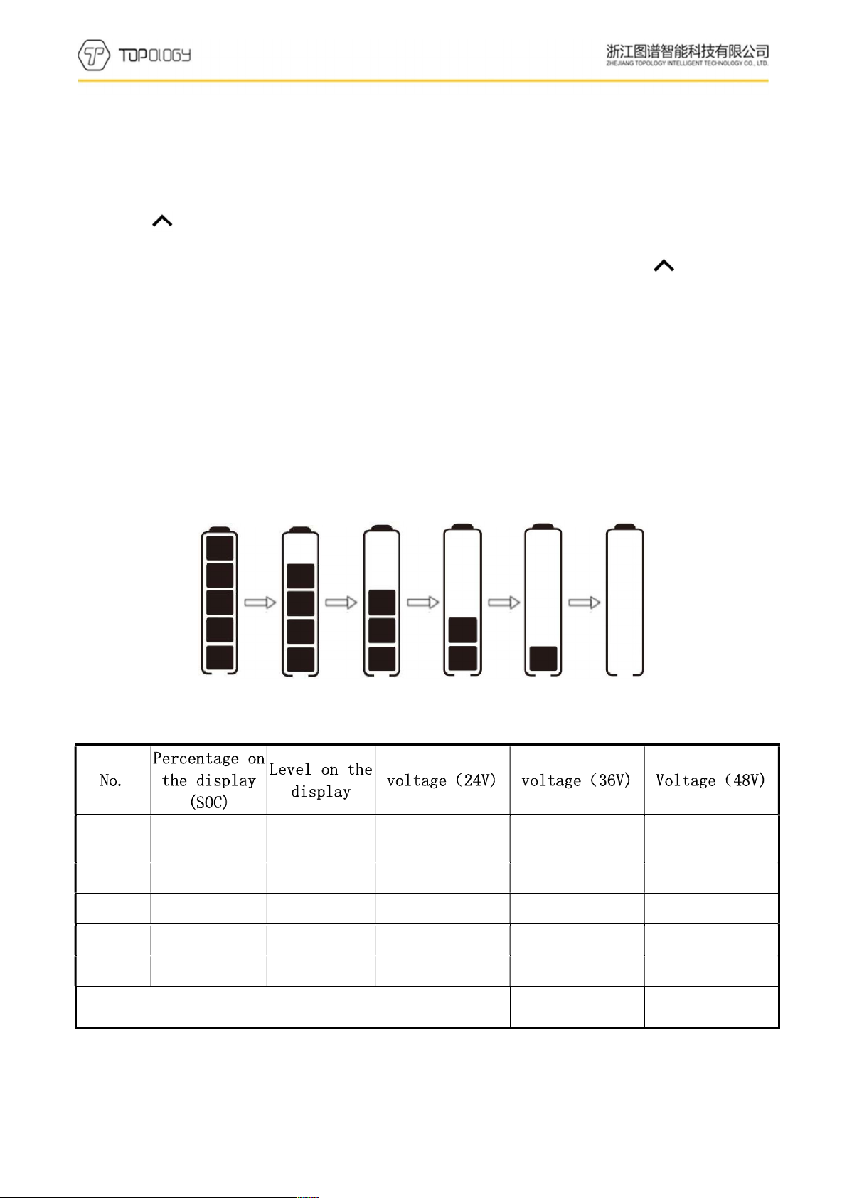
6.6Power indicator
When the battery is normal, the battery 5-segment LCD is displayed according to the time and
the outer border is on. When the battery is exhausted, the 5 full LCD and the outer border of the
battery indicator flashes, you need to charge immediately.The battery power is shown as below:
Percentage of battery power(C)and power level table
1 C≤5% Outer border
flashes U≤23.1 U≤33 U≤42.9
2 5%<C<15% 1 level power 23.1<U<24.5 33<U<34.7 42.9<U<45.1
3 15%≤C<35% 2 level power 24.5≤U<25.1 34.7≤U<35.8 45.1≤U<46.5
4 35%≤C<55% 3 level power 25.1≤U<25.6 35.8≤U<36.7 46.5≤U<47.5
5 55%≤C<75% 4 level power 25.6≤U<27 36.7≤U<38.5 47.5≤U<50.1
6 C≥75% 5 level power U≥27 U≥38.5 U≥50.1
第13 页/共17 页
Setting items: unit, *wheel diameter, *speed limitation information. ( * means fixed items, do not
provide user settings options)
7.1enter setting
²10 seconds within display turned on, long press (3seconds), system enter the data setting
interface. On this status users can set and view the parameters of the display.
²Long press (3 seconds) to exit and save the setting status.
²User settings interface state, if 10 seconds without the operation, display returns to normal riding
state without saving the parameter settings.
²On data setting state, short press /to switch setting items
²Short press to switch setting items circularly.
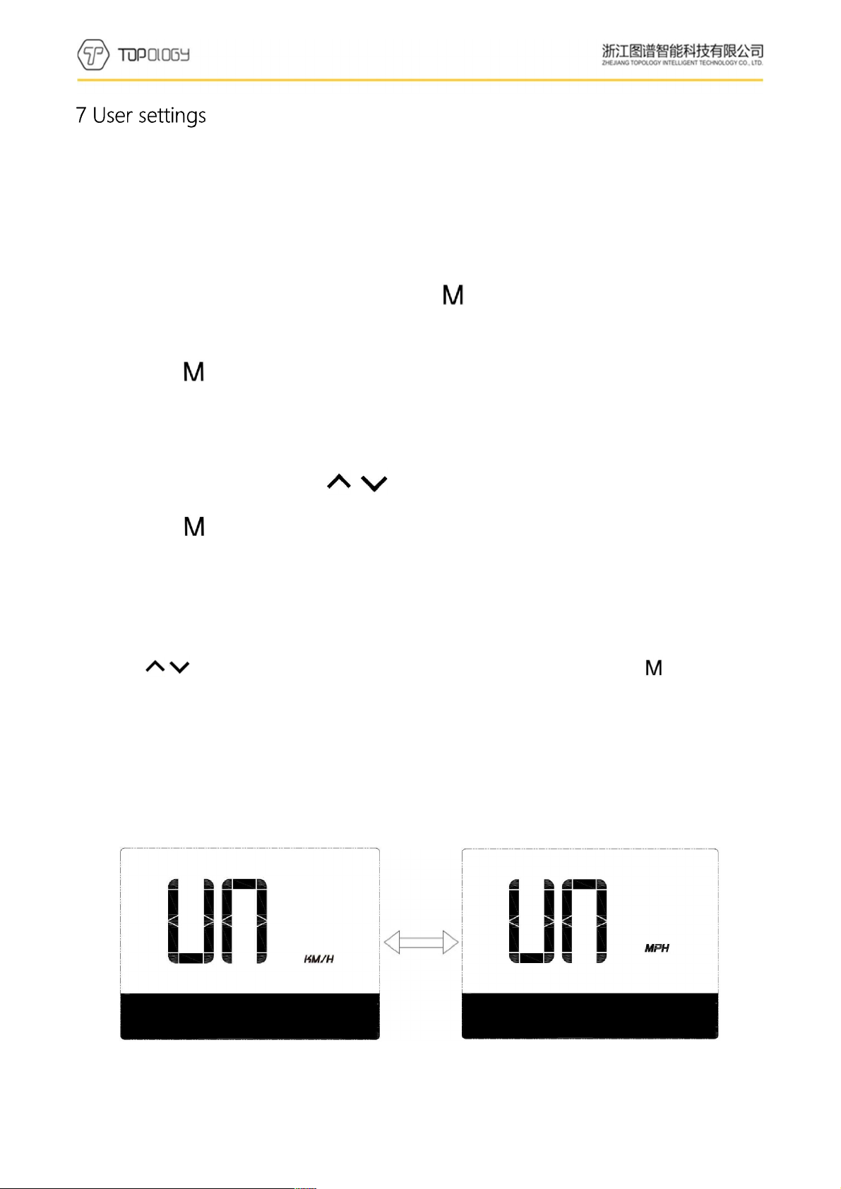
7.2unit setting
Press / to select KM/H or MPH in unit setting interface. Press (short) to switch
setting interface.
UN: unit setting
KM/H:The unit of trip mileage and total mileage is Km. The unit of current speed, average
speed; maximum speed is KM/H.
MPH:The unit of trip mileage and total mileage is Miles. The unit of current speed, average
speed; maximum speed is MPH.
The interface is shown as below:
Unit setting (KM/H) unit setting (MPH)
第14 页/共17 页
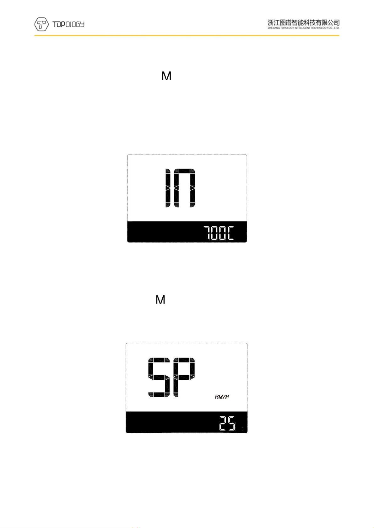
7.3wheel diameter information
In wheel information interface, short press to turn to speed limitation interface.
IN:wheel diameter information.
700C: means current display is setting for the bike of 700C wheel diameter.
Wheel diameter value can be set:16inch、18inch、20inch、22inch、24inch、26inch、700Cinch、
28inch、29inch.
The interface is shown as below:
Wheel diameter information(700C)
7.4Speed limitation information
In speed limitation interface, short press to turn to unit setting interface.
SP:speed limitation information
25KM:maximum speed is 25KM/H;
The interface is shown as below:

第15 页/共17 页
10 seconds after display turned on, long press (3 seconds),enter the data clearance interface.
Interface shows: speed, time, mileage, riding time, trip, unit.
Press (short) to clean TRIP, TRIP TIME, AVG speed and MAX speed. Then display return
to operation interface.Display will return to riding interface without data clearance if no operation
in 5 seconds.
Normal shutdown and power-down will not make the above dataclear.
Data clearance interfaceriding interface
9.1 error shown
Presenting error code and error icon

第16 页/共17 页
9.2 error code definition
Error code table:
Error code Fault description Checking methord
"04" shown at speed throttle doesn't turn back to zero position Check if the throttle return to zero position
"05" shown at speed throttle failure check throttle
"07" shown at speed overvoltage protection check the voltage of the battery
"08" shown at speed failure of motor's hall signal wire check the motor
"09" shown at speed failure of motor's phase wire check the motor
"11" shown at speed failure of the controller's temperature
sensor check the controller
"12" shown at speed failure of the current sensor check the controller
"13" shown at speed failure of the temperature of the battery check the battery
"14" shown at speed failure of the temperature of the motor check the motor
"21" shown at speed failure of the speed sensor check the position of the speed sensor
"22" shown at speed failure of the BMS communication check the battery
"30" shown at speed communication failure check the connector of the controller
Wires out of the display wires connect to the display connector to controller
Table 1 wires definition
No. Color Function
1 Red(VCC) VCC
2 Blue(Kp) Power control wire of the controller
3 Black (GND) GND of display
4 Green(RX) Data receive of the display
5 Yellow(TX) Data transmit of the display

第17 页/共17 页
²In the use of the display, pay attention to the security, do not plug the display in and out the when
the power is on.
²Try to avoid use exposurein harsh environments like heavy rain, heavy snow, and strong sunlight
²When the display can’t be used normally, it should be send to repair as soon as possible.
Table of contents


