TOPSCCC EX-9541N User manual

RS-422/485 to Fiber
Converter
User’s Guide
COPYRIGHT
All rights reserved. No part of this publication may be reproduced,
stored in a retrieval system, or transmitted in any form or by any means,
whether electronic, mechanical, photo copying, recording or otherwise,
without the prior written permission of the publisher.
FCC WARNING
This equipment has been tested and found to comply with the
limits for class A device, pursuant to part 15 of FCC rules.
These limits are designed to provide reasonable protection against
harmful interference in a commercial installation. This equipment
generates, uses and can radiate radio frequency energy and, if not
installed and used in accordance with the instructions, may cause
harmful interference to radio communication. Operation of this
equipment in a residential area is likely to cause harmful interference, in
which case, the user will be required to correct the interference at the
user’s own expense.
CE
This is a Class A product. In a domestic environment, this
product may cause radio interference in which case the user
may be required to take adequate measures.
Take special note to read and understand all content giving in the
warning boxes Warning

TABLE OF CONTENTS
ABOUT THIS GUIDE............................................................ 4
PURPOSE ................................................................................ 4
TERMS/USAGE ....................................................................... 4
INTRODUCTION................................................................... 5
FEATURES.............................................................................. 5
THE INDUSTRIAL CONVERTER UNPACKING AND
SETUP .................................................................................... 5
UNPACKING ........................................................................... 6
LAYOUT OF THE CONVERTER................................................. 7
DIN RAIL MOUNTING OF THE CONVERTER............................ 8
WALL MOUNTING THE CONVERTER ...................................... 9
POWER INPUTS....................................................................... 9
FIBER CONNECTION ............................................................. 10
SERIAL CONNECTION........................................................... 11
LED INDICATORS ................................................................ 11
DIP SWITCH SETTINGS ........................................................ 12
TECHNICAL SPECIFICATIONS...................................... 12

4
ABOUT THIS GUIDE
Thank you for choosing RS-422/485 to Fiber Converter. This
device integrates serial and multi-mode/single mode fiber
networks in one flexible package.
The Industrial Series (RS-422/485 to Fiber) Converter provides
a reliable and economical solution for your industrial Ethernet
environment. The converter offers seamless integration while
working as transparent device between your serial devices and
industrial Ethernet. The Converter has operating temperature
range from 0 to 50°C. Fiber enables you to extend the
distances up to 120km.
Purpose
This guide discusses how to install the Industrial Series
Converter.
Terms/Usage
In this guide, the term “Converter” (first letter upper case)
refers to the RS-422/485 to Fiber Industrial Converter,
and ”converter” (first letter lower case) generically refers to all
other Ethernet converters.

5
INTRODUCTION
This chapter describes the features and specification of
the Converter.
Features
• Complies with EIA/TIA-422 & 485 standards
• Supports data transfer rate up to 115.20kbps
• Available with ST/SC connector for Multi-mode or SC
connector for Single Mode
• Extends distance of up to 2km (6600 feet) multi-
mode fiber and 120km (396000 feet) long-haul single
mode fiber
• DIP switch for 4-wire full and 2-wire asynchronous
transmission
• Extends distances up to 1.2km for 24AWG Twisted
Pair Cable
• DIP switches to enable/disable Termination
• LEDs for at-a-glance device status
• Suitable for industrial harsh environment
• Wide voltage range (9 ~ 32V DC)
• FCC Class A & CE approved
THE INDUSTRIAL CONVERTER

6
UNPACKING AND SETUP
This section and the following sections explain the setup
and installation of the Industrial Converter.
Unpacking
Open the box of the Converter and carefully unpack it.
The box should contain the following items:
One RS-422/485 to Fiber Converter
DIN rail bracket screws (optional)
One AC power adaptor (please check connector type and
input power specifications)
DIN Rail Kit (Optional)
Protective caps for unused ports
This User’s Guide
If any item is found missing or damaged, please contact
your local reseller for replacement.
7
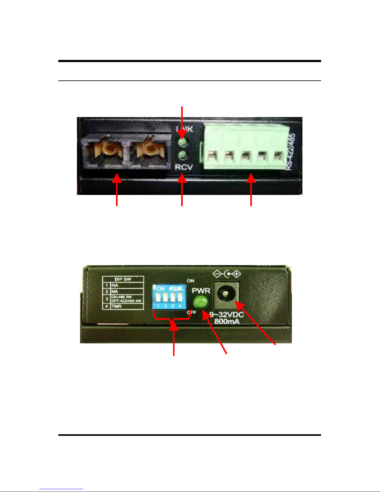
Layout of the Converter
Front View of Converter
LINK
LED
RECEIVE
LED RS-422/485 port
(terminal block)
Fiber port
Rear View of Converter
Power
LED
Power
Connector
DIP Switches

8
DIN Rail Mounting of the Converter
The aluminum DIN Rail attachment plate should already
be affixed to the back panel of the Converter. If you need
to attach the DIN Rail plate, assure that the stiff metal
spring is situated towards the top. Attaching the
Converter to the DIN rail is easy, just align, and attach
the top rail, then press down and snap forward the
Converter to snap in the bottom rail, as shown in the
figures below.
The setup of the Converter can be performed using the
following steps:
• The surface must support at least 600 gm for the
Converter.
• The power outlet should be within 1.82 meters (6 feet)
of the Converter.
• Visually inspect the power adapter and make sure
9
that it is properly connected.
• Make sure that there is proper heat dissipation from
and adequate ventilation around the Converter. Do
not place heavy objects on the Converter.
Wall Mounting the Converter
The Converter can also be installed by wall mounting.
The backside casing provides space for two screws each
side. Identify the exact location at wall by placing the
Converter and marking the screw positions. Use the
screw (include in the package) and snug them well to fix
the Converter.
Power Inputs
Use the provided power adapter for power supply. Plug
the power adapter’s DC plug into the Converter’s DC-IN
jack and then power adapter into an electrical outlet.
Power Adapter: Only use the recommended specific
Power adapter provided with Converter. Check the technical
specificationsectionfor information about thepower input voltage.
Since theConverter does not include apower switch, pluggingits
power adapter into a power outlet will immediately power it on.

10
Fiber Connection
When connecting fiber cable to the Converter, be sure
the correct type – ST or SC - connector is used. Follow
the steps below to properly connect fiber cable:
1. Remove and keep the ST/SC port rubber
covers. When not connected to a fiber cable,
the rubber cover should be replaced to protect
the optics.
2. Check that the fiber terminators are clean. You
can clean the cable plugs by wiping them
gently with a clean tissue or cotton ball
moistened with a little ethanol. Dirty fiber
terminators on fiber optic cables will impair the
quality of the light transmitted through the
cable and lead to degraded performance on
the port.
3. Connect one end of the cable to the ST/SC
port on the Converter and the other end to the
ST/SC port on the other device.
4. Check the corresponding port LED on the
Converter to be sure that the connection is
valid. (Refer to the LED chart)
Warning Because invisible laser radiation may be emitted from
the aperture of the port when no cable is connected, avoid
exposure to laser radiation and do not stare into open apertures.

11
Serial Connection
The 5-pin terminal block connector is provided at the
front panel of the Converter. During shipping, the
removable green terminal block may already be detached
from the five pin terminal contact point. It may be easier
to attach the serial cable wires to the green terminal
block if it has first been unplugged from the terminal
contact point on the Converter.
On the terminal block, use a flathead screwdriver to
loosen the screws and then insert the related cable as
shown in the figure below. Tighten screws until snug.
RS-422/485 cabling
LED Indicators
The Converter has following LEDs.
Power Indicator (PWR): This LED lights green when the
Converter is receiving power from input. It is located
beside the power adapter pin.
RCV LED

12
Illuminates (green) to indicate when receiving data from a
compliant device at serial port.
LNK LED
Illuminates to indicate receiving link pulses from a
compliant device at fiber port.
DIP Switch Settings
DIP Switches allow for the user to manually
enable/disable external alarms, 2-wire / 4-wire cable
mode, and TMR functions. The figure below shows the
DIP switch control.
DIP 1 (N/A)
DIP 2 (N/A)
DIP 3 (2-wire / 4-wire) Enable the serial port wire function
to either 2-wire or 4-wire (ON:485 2-wire, OFF: 422/485
4-wrie). Default is OFF.
DIP 4 (TMR) Enable/Disable RS-422/485 terminator.
Default is OFF (Disable).
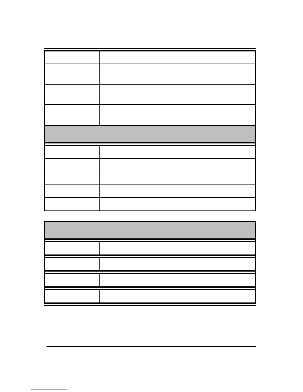
TECHNICAL SPECIFICATIONS
General
13
Standards EIA/TIA-422, EIA/TIA-485
Connectors 1 (one) serial port (RS-422/485)
ST/SC for multi-mode, SC for single mode
Wavelength 1310nm (multi-mode)
1310nm ~ 1550 (single mode)
Max Distances RS-422/485 – 1,200 meters
Fiber Optic – Up to 120,000 meters
Physical and Environmental
Power Input 9-32V DC @ 800mA
Temperature Operating: 0°~ 50°C, Storage: -20°~ 80°C
Humidity Operating: 10% ~ 80%
Dimensions 109.20 x 90 x 31.50 mm (D x W x H)
Compliance FCC Class A, CE approved
DIP Switches
Dip 1 N/A
Dip 2 N/A
Dip 3 2-wire (RS-485 OR 4-wire (RS-422/485)
Dip 4 RS-422/485 Terminator

14
Table of contents
Popular Media Converter manuals by other brands


Baumer
Baumer HOG 16 M + DSL Installation and operating instructions

Connective Peripherals
Connective Peripherals ES-U Series manual

Cayin
Cayin RU6 quick guide

TR-Electronic
TR-Electronic Profibus 582 Series Assembly instructions

Digitus
Digitus DN-82212 Quick installation guide

GoMax Electronics
GoMax Electronics MX-5022 user manual