Niko 16-661-01 User manual

16-661-01 / 16-660-01 / 16-660-02
1NL
Lees de volledige handleiding vóór installatie en ingebruikname.
1. BESCHRIJVING
De 16-661-01 is een videobinnenpost en behoort tot het gamma Toegangscontrole Design. Op dit toestel kan een kleurenbeeld van uw bezoeker weer-
gegeven worden terwijl u met hem/haar spreekt. De videobinnenpost is geschikt voor opbouw op een wand (standaard). Hij kan ook gebruikt worden als
vrijstaand toestel. U kan de hellingsgraad regelen met behulp van de bijgeleverde voet (16-660-01). U kan de videobinnenpost ook gedeeltelijk verzonken in
de wand monteren met behulp van een speciale montagebox (16-660-02). De videobinnenpost 16-661-01 wordt gevoed via de UTP-kabel van de instal-
latie. De binnenpost is voorzien van een vlak kleuren-LCD-beeldscherm. Voor een beschrijving van het volledige systeem verwijzen wij naar de catalogus
of naar www.niko.be.
2. MONTAGE
2.1. Controleer of u over de volgende componenten beschikt:
- Videobinnenpost 16-661-01
- UTP-kabel, CAT.5E (van de videosplitter of videoswitcher tot aan de videobinnenpost) met RJ45-connectoren aan weerszijden.
De UTP-kabel verbindt de 16-661-01 met de videosplitter of -switcher (max.100m).
Deze UTP-kabel (CAT.5E) bevat de aders voor aansluiting op de voeding, de analoge telefoonlijn, het videosignaal en een bus.
Kleurencode UTP-kabel:
1. oranje-wit 1. Vsup (+)
2. oranje 2. Ground (-)
3. groen-wit 3. bus H
4. blauw 4. telefonie (tip)
5. blauw-wit 5. telefonie (ring)
6. groen 6. bus L
7. bruin-wit 7. video +
8. bruin 8. video -
4 TEL tip
5 TEL ring
7 VIDEO +
8 VIDEO -
1 + Vsup
2 - Gnd
3 Bus H
6 Bus L
Opgelet!
Verkeerde bekabeling
kan de producten in
het systeem ernstig
beschadigen!
2.2. Montage als opbouwtoestel
Plaats de videobinnenpost 16-661-01 op de muur zoals aangegeven in fig.1. Voorzie in een standaardinbouwdoos op de aangegeven plaats.
2.3. Montage als inbouwtoestel
Plaats de videobinnenpost 16-661-01 zoals aangegeven in fig. 2, 3 en 4. Voorzie eerst in een standaardinbouwdoos achter het inbouwraam (16-660-02)
op de aangegeven plaats. Monteer vervolgens het inbouwraam boven de inbouwdoos. De opening in de wand moet de volgende afmetingen hebben: L221
x B188 x D21mm.
Let wel: Hou rekening met de diepte van het inbouwraam om de standaardinbouwdoos te plaatsen.
2.4. Montage als vrijstaand toestel op een voet (16-660-01)
Monteer de voet zoals in fig. 5. Kies de bevestigingspunten die ervoor zorgen dat uw blik loodrecht op het scherm valt.
3. PROGRAMMERING
Via de interface 16-651 zet u het systeem in programmeermode of resetmode.
Voor een uitvoerige beschrijving van de programmering, zie handleiding van de 16-651.
De 16-661-01 of binnenpost geeft feedback tijdens de programmering. Haak de hoorn af.
- in programmeermode:
* 5 beeptonen: adres opgeslagen.
* geen beeptoon: adres was reeds opgeslagen.
- in resetmode:
* 5 beeptonen: binnenpost gewist.
* geen beeptoon: binnenpost was reeds gewist.
4. WERKING EN GEBRUIK
Als de installatie correct geprogrammeerd werd, licht het scherm van de juiste binnenpost(en) op als er aangebeld wordt. U kan de bezoeker zien zonder
de hoorn van het toestel te nemen, ook als de oproep naar een ander toestel doorgeschakeld wordt (audio en video worden apart geprogrammeerd). Het
scherm blijft actief zolang de oproep duurt.
4.1. Een oproep beantwoorden
Als de oproep effectief naar het toestel doorgeschakeld wordt, rinkelt dit toestel. Haak de hoorn af om met uw bezoeker te communiceren. Tijdens het
gesprek kan u de elektrische sloten bedienen. Druk hiervoor op toets 1 of 2 (afhankelijk van het slot dat u wil bedienen) (zie handleiding 16-651). Druk op
✱om het gesprek te beëindigen.
4.2. Een buitenpost activeren (beeld en communicatie)
U kan de buitenpost activeren zonder dat er werd aangebeld. Bel hiervoor via de centrale naar de elektronische controle-eenheid 16-651 en schakel de
deurtelefoon in (toets 3). De camera, de luidspreker én de microfoon worden geactiveerd. Als u meerdere deurposten/camera’s aangesloten en op de
videobinnenpost 16-661-01 geprogrammeerd hebt, kan u het camerabeeld hiervan één voor één doorlopen. Druk hiervoor telkens opnieuw op toets 3.
Druk op ✱om het gesprek te beëindigen.

16-661-01 / 16-660-01 / 16-660-02
2 NL
4.3. Telefoonfuncties
U kan het toestel gebruiken als een normaal analoog telefoontoestel met alle functies die de analoge lijn van de aangesloten telefooncentrale toelaat. De
telefoon is voorzien van een magnetisch inhaakcontact dat geactiveerd wordt als de hoorn bij het toestel gehouden wordt.
4.4. Helderheid beeld instellen
Wijzig de helderheid van het beeld als het display actief is.
Hou drukknop ingedrukt om de helderheidscyclus te doorlopen. Helderheidscyclus: min. max.
4.5. Beeldcontrast instellen
Wijzig het beeldcontrast als het display actief is.
Hou drukknop ingedrukt om de contrastcyclus te doorlopen. Contrastcyclus: min. max.
4.6. Beeld oproepen
Met drukknop kan u het beeld van een buitenpost of externe camera oproepen. Indien het systeem meerdere buitenposten/camera’s bevat, kan
het beeld* van een volgende buitenpost/camera bekeken worden met een druk op de knop. Na het beeld van een laatste buitenpost/camera kan u het
beeld uitschakelen met een druk op de knop.
(*)LET OP: enkel de beelden van de buitenposten/camera’s die op de videobinnenpost 16-661-01 geprogrammeerd zijn, zijn zichtbaar. Voor programmering,
zie handleiding elektronische controle-eenheid 16-651.
5. TECHNISCHE GEGEVENS
Afmetingen................................. L216 x B180 x H42mm
Gewicht...................................... 1350g
Bedrijfstemperatuur ....................0 tot 40°C
Behuizing ................................... aluminium (gelakt)
Toetsen ...................................... geanodiseerd aluminium
Connector:.................................. RJ45
Voeding:..................................... meegeleverd via de RJ45-verbinding
Video-ingang:............................. twisted pair 1Vpp composiet
Schermresolutie (beeldpunten):.... 480 horizontaal, 234 verticaal
Analoge telefooningang:..............lijnimpedantie 600Ω(enkel voor aansluiting op een private telefooncentrale)
Ontworpen volgens de voorschriften van TBR 21
Tone dialing (DTMF)
6. ONDERHOUD VAN HET PRODUCT
Aan de hand van onderstaande onderhoudstips willen wij vermijden dat het oppervlak van deze luxeproducten door verkeerde behandeling beschadigd
wordt. Beschadiging door verkeerde behandeling valt niet onder de garantie.
Onderhoudstips
- Het volstaat de producten te reinigen met wat zeep en een vochtige doek.
- Gebruik van volgende producten wordt ten zeerste afgeraden:
- schurende sponzen of schurende reinigingsmiddelen;
- onderhoudsmiddelen die een oplosmiddel of een zuur bevatten of schoonmaakmiddelen met azijnzuur.
7. WETTELIJKE WAARSCHUWINGEN
- De installatie dient te worden uitgevoerd door een erkend installateur en met inachtname van de geldende voorschriften.
- Deze handleiding dient aan de gebruiker te worden overhandigd. Zij moet bij het dossier van de elektrische installatie worden gevoegd en dient te worden overgedragen
aan eventuele nieuwe eigenaars. Bijkomende exemplaren zijn verkrijgbaar via de Niko-website of -supportdienst.
- Bij de installatie dient rekening gehouden te worden met (lijst is niet limitatief):
- de geldende wetten, normen en reglementen;
- de stand van de techniek op het ogenblik van de installatie;
- het feit dat een handleiding alleen algemene bepalingen vermeldt en dient gelezen te worden binnen het kader van elke specifieke installatie;
- de regels van goed vakmanschap.
- Bij twijfel kan u de supportdienst van Niko raadplegen of contact opnemen met een erkend controleorganisme.
Support België: Support Nederland:
tel. + 32 3 778 90 80 tel. + 31 183 64 06 60
website: http://www.niko.be website: http://www.niko.nl
In geval van defect kan u uw product terugbezorgen aan een erkende Niko-groothandel samen met een duidelijke omschrijving van uw klacht (manier van gebruik,
vastgestelde afwijking…).
8. GARANTIEBEPALINGEN
- Garantietermijn: twee jaar vanaf leveringsdatum. Als leveringsdatum geldt de factuurdatum van aankoop van het goed door de consument. Indien geen factuur
voorhanden is, geldt de productiedatum.
- De consument is verplicht Niko schriftelijk over het gebrek aan overeenstemming te informeren, uiterlijk binnen de twee maanden na vaststelling.
- In geval van een gebrek aan overeenstemming van het goed heeft de consument recht op een kosteloze herstelling of vervanging, wat door Niko bepaald wordt.
- Niko is niet verantwoordelijk voor een gebrek of schade als gevolg van een foutieve installatie, oneigenlijk of onachtzaam gebruik of verkeerde bediening of transfor-
matie van het goed.
- De dwingende bepalingen van de nationale wetgevingen betreffende de verkoop van consumptiegoederen en de bescherming van de consumenten van de landen
waarin Niko rechtstreeks of via zuster/dochtervennootschappen, filialen, distributeurs, agenten of vaste vertegenwoordigers verkoopt, hebben voorrang op boven-
staande bepalingen.

16-661-01 / 16-660-01 / 16-660-02
3
Lisez entièrement le mode d’emploi avant toute installation et mise en service.
1. DESCRIPTION
Le 16-661-01 est un poste intérieur vidéo qui fait partie de la gamma Contrôle d’Accès Design. Une image couleur de votre visiteur peut être affichée sur
cet appareil pendant que vous conversez avec lui. Le poste intérieur vidéo convient pour être installé en saillie sur un mur (standard). Il peut également
être utilisé comme appareil indépendant. Vous pouvez régler le degré d’inclinaison à l’aide du pied fourni (16-660-01). Vous pouvez également monter
le poste intérieur vidéo partiellement enchâssé à l’aide d’une boîte de montage spéciale (16-660-02). Le poste intérieur 16-661-01 est alimenté via le
câble UTP de l’installation. Le poste intérieur est équipé d’un écran plat LCD couleur. Pour une description du système complet, nous vous reportons au
catalogue ou au site internet www.niko.be.
2. MONTAGE
2.1. Contrôlez si vous possédez les éléments suivants:
- Poste intérieur vidéo 16-661-01
- Câble UTP CAT.5E (du répartiteur vidéo ou du sélecteur vidéo jusqu’au poste intérieur vidéo 16-661-01) avec des connecteurs RJ45 de part et d’autre.
Le câble UTP relie le 16-661-01 au répartiteur ou au sélecteur vidéo (max.100m).
Ce câble UTP (CAT.5E) comprend les conducteurs pour le raccordement à l’alimentation, la ligne téléphonique analogique, le signal vidéo et un bus.
Code des couleurs du câble UTP:
1. orange-blanc 1. Vsup (+)
2. orange 2. Ground (-)
3. vert-blanc 3. bus H
4. bleu 4. téléphonie (tip)
5. bleu-blanc 5. téléphonie (ring)
6. vert 6. bus L
7. brun-blanc 7. vidéo +
8. brun 8. vidéo -
4 TEL tip
5 TEL ring
7 VIDEO +
8 VIDEO -
1 + Vsup
2 - Gnd
3 Bus H
6 Bus L
Attention!
Un câblage erroné peut sé-
rieusement endommager
les produits du système!
2.2. Montage comme appareil en saillie
Positionnez le poste intérieur 16-661-01 sur le mur comme indiqué à la fig.1. Prévoyez une boîte d’encastrement standard à l’endroit indiqué.
2.3. Montage comme appareil encastré
Positionnez le 16-661-01 comme indiqué à la fig. 2, 3 et 4. Prévoyez d’abord une boîte d’encastrement standard derrière le support à encastrer (16-
660-02) à l’endroit indiqué. Montez ensuite le support à encastrer au-dessus de la boîte d’encastrement. L’ouverture dans le mur doit avoir les dimensions
suivantes: L221 x l188 x P21mm.
Attention: tenez compte de la profondeur du support à encastrer pour installer la boîte d’encastrement standard.
2.4. Montage en tant qu’appareil indépendant sur un pied (16-660-01)
Montez le pied comme illustré à la fig. 5. Choisissez les points de fixation qui permettent à votre regard de tomber perpendiculairement sur l’écran.
3. PROGRAMMATION
Via l’interface 16-651, vous placez le système en mode programmation ou en mode d’effacement.
Pour une description détaillée de la programmation, consultez le mode d’emploi du 16-651.
Le 16-661-01 ou poste intérieur donne un feed-back au cours de la programmation. Décrochez le combiné.
- en mode programmation:
* 5 bips: adresse sauvegardée.
* pas de bip: adresse était déjà sauvegardée.
- en mode d’effacement:
* 5 bips: poste intérieur effacé.
* pas de bip: poste intérieur était déjà effacé.
4. FONCTIONNEMENT ET UTILISATION
Si l’installation a été correctement programmée, l’écran du (des) poste(s) intérieur(s) adéquat(s) s’allume lorsque l’on sonne à la porte.Vous pouvez voir le
visiteur sans décrocher le combiné de l’appareil, même lorsque l’appel est transféré vers un autre appareil (l’audio et la vidéo sont programmés séparé-
ment). L’écran reste actif aussi longtemps que dure l’appel.
4.1. Répondre à un appel
Si l’appel est effectivement transféré vers l’appareil, cet appareil sonne. Décrochez le combiné pour communiquer avec votre visiteur. Pendant la conversa-
tion, vous pouvez commander les gâches électriques. Pour ce faire, appuyez sur la touche 1 ou 2 (en fonction de la gâche que vous souhaitez commander)
(voir le manuel 16-651). Appuyez sur ✱pour mettre fin à la conversation.
4.2. Activer un poste extérieur (image et communication)
Vous pouvez activer le poste extérieur sans que l’on ne sonne. Pour ce faire, appelez l’unité de contrôle éléctronique 16-651 via le central et commutez
le parlophone (touche 3). La caméra, le haut-parleur et le microphone sont activés. Si vous avez raccordé plusieurs postes de rue/caméras et les avez
programmés sur le poste intérieur 16-661-01, vous pouvez les parcourir un par un. Pour ce faire, appuyez chaque fois de nouveau sur la touche 3.Appuyez
sur ✱pour mettre fin à la conversation.
FR

16-661-01 / 16-660-01 / 16-660-02
4
4.3. Fonctions du téléphone
Vous pouvez utiliser l’appareil comme un appareil téléphonique analogique normal avec toutes les fonctions qu’autorise la ligne analogique du central télé-
phonique raccordé. Le téléphone est muni d’un contact de raccrochage magnétique qui est activé lorsque le combiné est tenu à proximité de l’appareil.
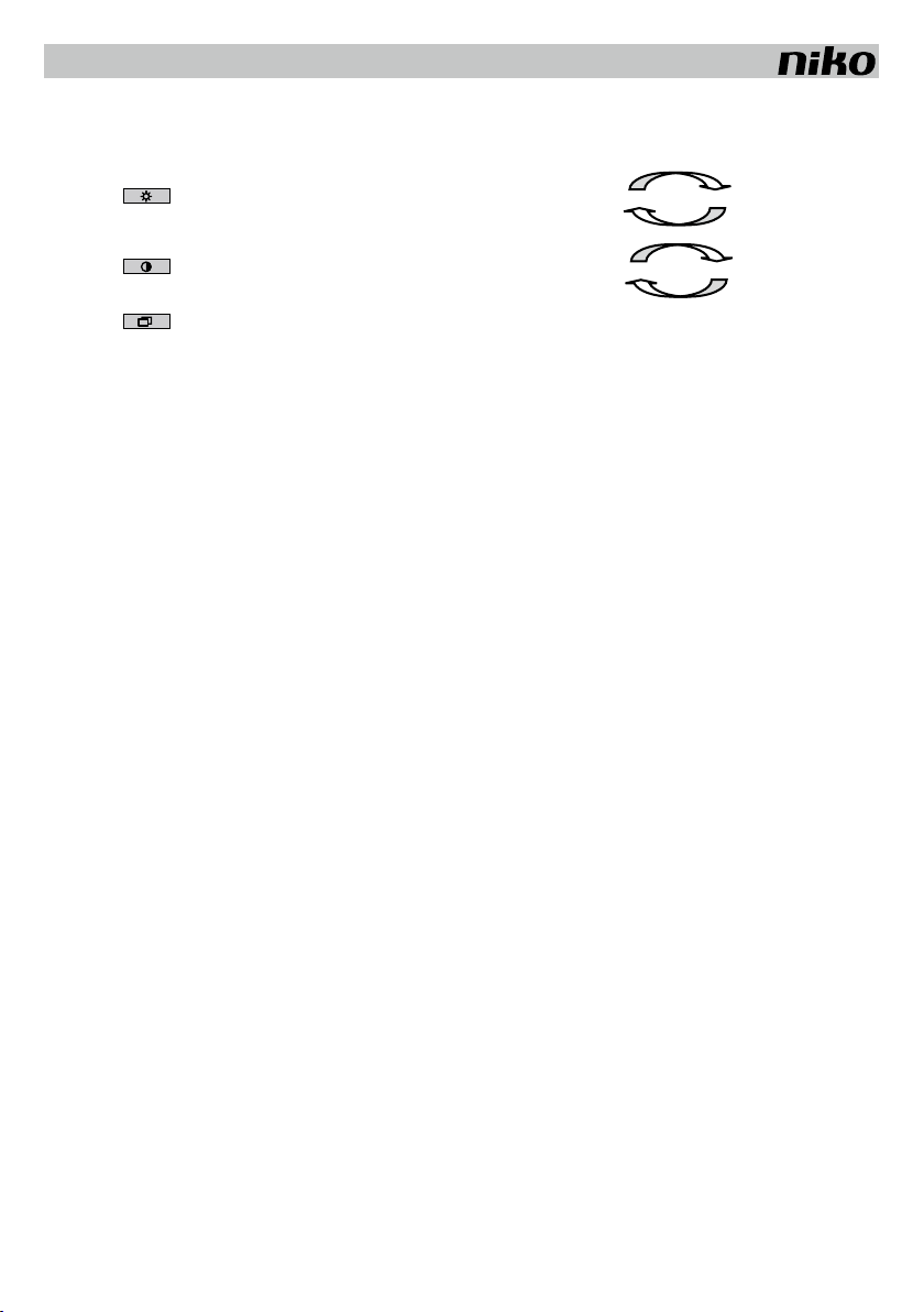
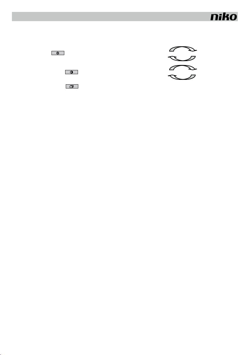
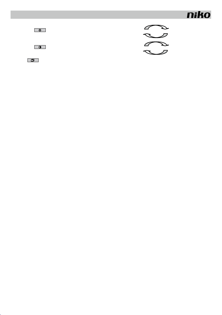
4.4. Régler la luminosité de l’image
Modifiez la luminosité de l’image lorsque l’écran est actif.
Gardez le bouton-poussoir enfoncé pour parcourir le cycle de luminosité. Cycle de luminosité: min. max.
4.5. Régler le contraste de l’image
Modifiez le contraste de l’image lorsque l’écran est actif.
Gardez le bouton-poussoir enfoncé pour parcourir le cycle du contraste. Cycle du contraste: min. max.
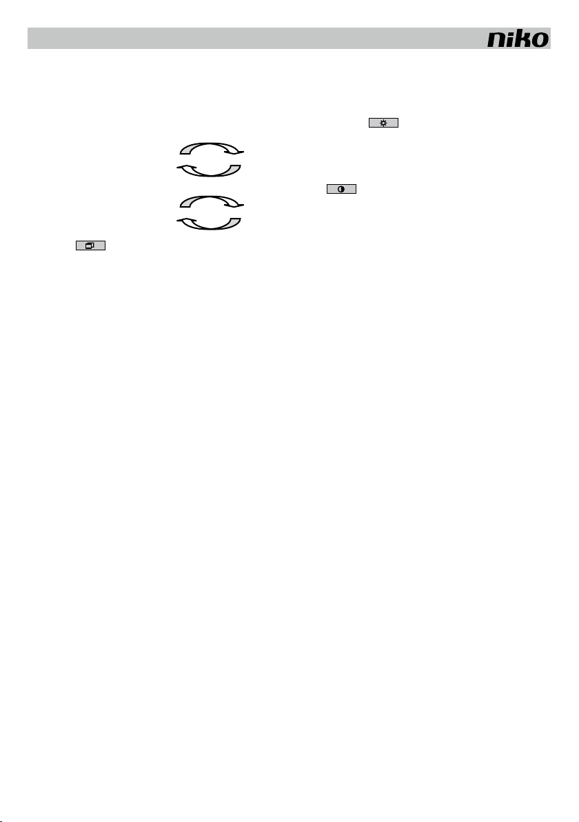
4.6. Appeler une image
En appuyant sur le bouton-poussoir , vous pouvez appeler l’image d’un poste extérieur ou d’une caméra externe. Si le système est composé de
plusieurs postes extérieurs/caméras, l’image* du poste extérieur/de la caméra suivant(e) peut être consultée en appuyant sur le bouton. Après avoir vu
l’image du dernier poste extérieur/caméra, vous pouvez couper l’image en appuyant sur le bouton.
(*)ATTENTION: seules sont visibles les images des postes extérieurs/caméras qui sont programmés sur le poste intérieur 16-661-01. Pour la programma-
tion, voir le manuel de l’unité de contrôle éléctronique 16-651.
5. CARACTERISTIQUES TECHNIQUES
Dimensions ................................L216 x l180 x H42mm
Poids.......................................... 1350g
Température de service...............de 0 à 40°C
Boîtier ........................................ aluminium (laqué)
Touches ..................................... aluminium anodisé
Connecteur:................................ RJ45
Alimentation: .............................. fournie via la connexion RJ45
Entrée vidéo:...............................câble torsadé 1Vpp composite
Résolution écran (pixels):............. 480 à l’horizontale, 234 à la verticale
Entrée téléphonique analogique: .. impédance de ligne 600Ω(uniquement pour raccordement à un central téléphonique privé)
Conçu selon les prescriptions de TBR 21
Tone dialing (DTMF)
6. ENTRETIEN DU PRODUIT
Les conseils d’entretien ci-dessous visent à éviter que la surface de ces produits ne soit endommagée par un traitement inadapté. Les dommages causés
par un traitement inadapté ne sont pas couverts par la garantie.
Conseils d’entretien
- Le nettoyage des produits avec un linge humide et un peu de savon suffit.
- L’utilisation des produits suivants est strictement déconseillée:
- éponges abrasives ou détergents abrasifs
- produits d’entretien contenant un solvant ou un acide ou à l’acide acétique.
7. PRESCRIPTIONS LEGALES
- L’installation doit être effectuée par un installateur agréé et dans le respect des prescriptions en vigueur.
- Ce mode d’emploi doit être remis à l’utilisateur. Il doit être joint au dossier de l’installation électrique et être remis à d’éventuels autres propriétaires. Des exemplaires
supplémentaires peuvent être obtenus sur le site web ou auprès du service ‘support Niko’.
- Il y a lieu de tenir compte des points suivants avant l’installation (liste non limitative):
- les lois, normes et réglementations en vigueur;
- l’état de la technique au moment de l’installation;
- ce mode d’emploi qui doit être lu dans le cadre de toute installation spécifique;
- les règles de l’art.
- En cas de doute, vous pouvez appeler le service ‘support Niko’ ou vous adresser à un organisme de contrôle reconnu.
Support Belgique: Support France:
+ 32 3 778 90 80 + 33 820 20 66 25
site web: http://www.niko.be site web: http://www.niko.fr
En cas de défaut de votre appareil, vous pouvez le retourner à un grossiste Niko agréé, accompagné d’une description détaillée de votre plainte (manière d’utilisation,
divergence constatée…).
8. CONDITIONS DE GARANTIE
- Délai de garantie: 2 ans à partir de la date de livraison. La date de la facture d’achat par le consommateur fait office de date de livraison. Sans facture disponible, la
date de fabrication est seule valable.
- Le consommateur est tenu de prévenir Niko par écrit de tout manquement à la concordance des produits dans un délai max. de 2 mois après constatation.
- Au cas ou pareil manquement serait constaté, le consommateur a droit à une réparation gratuite ou à un remplacement gratuit selon l’avis de Niko.
- Niko ne peut être tenu pour responsable pour un défaut ou des dégâts suite à une installation fautive, à une utilisation contraire ou inadaptée ou à une transformation
du produit.
- Les dispositions contraignantes des législations nationales ayant trait à la vente de biens de consommation et la protection des consommateurs des différents pays où
Niko procède à la vente directe ou par entreprises interposées, filiales, distributeurs, agents ou représentants fixes, prévalent sur les dispositions susmentionnées.
FR

16-661-01 / 16-660-01 / 16-660-02
5DE
Lesen Sie vor der Montage und Inbetriebnahme die vollständige Gebrauchsanleitung.
1. BESCHREIBUNG
Das 16-661-01 ist eine Videotürsprechanlage und gehört zum Programm: Design - Zugangskontrollsysteme. Dieses Gerät ermöglicht die Farbbildwie-
dergabe von einem Besucher während man mit ihm spricht. Die Videotürsprechanlage wird standardmäßig als Aufputzgerät zur Montage auf einer Wand
geliefert. Das Gerät kann auch freistehend aufgestellt werden. Die Neigung des Gerätes wird mit dem mitgelieferten Aufstellfuß (16-660-01) eingestellt.
Man kann die Video-Türsprechanlage auch als teilweise Unterputzversion mit einer speziellen Montagebox (16-660-02) in eine Wand montieren. Die
Videotürsprechanlage16-661-01 wird über das UTP-Kabel der Anlage mitversorgt. Die Anlage enthält einen völlig flachen Farb-LCD-Bildschirm. Die Be-
schreibung des gesamten Systems finden Sie in unserem Katalog oder auf unserer Webseite www.niko.be.
2. MONTAGE
2.1. Kontrollieren Sie, ob die folgenden Teile vorhanden sind:
- Videotürsprechanlage 16-661-01
- UTP-Kabel, CAT.5E (von dem Videosplitter oder -Switcher zur Videotürsprechanlage) mit RJ45-Steckern an beide Enden.
Das UTP-Kabel verbindet die Anlage mit dem Videosplitter oder –Switcher (max. 100m).
Dieses UTP-Kabel (CAT.5E) enthält die Adern zum Anschluss an die Spannungsversorgung, die analoge Nebenstelle, das Videosignal und einen Bus.
Farbkode des UTP-Kabels:
1. orange - weiß 1. Vsup (+)
2. orange 2. Masse (-)
3. grün – weiß 3. Bus H
4. blau 4. Telephonie (Tip)
5. blau- weiß 5. Telephonie (ring)
6. grün 6. Bus L
7. braun - weiß 7. Video +
8. braun 8. Video –
4 TEL tip
5 TEL ring
7 VIDEO +
8 VIDEO -
1 + Vsup
2 - Gnd
3 Bus H
6 Bus L
Achtung!
Eine falsche Verdraht-
ung kann die Produkte
im System schwer be-
schädigen!
2.2. Montage als Aufputzgerät
Die Videotürsprechanlage 16-661-01 wird wie in Zeichnung 1 dargestellt auf die Wand montiert. Eine Standard UP-Dose ist an dieser Stelle vorzusehen.
2.3. Montage als Unterputzgerät
Das 16-661-01 wird wie in Zeichnung 2, 3 und 4 dargestellt montiert. Eine Standard UP-Dose ist zuerst an der angegebenen Stelle hinter dem Ein-
baurahmen (16-660-02) vorzusehen. Danach wird der Einbaurahmen auf der UP-Dose montiert. Die Ausbruchöffnung in der Wand muss die folgenden
Abmessungen haben: L221 x B188 x T21mm.
Achtung: Man beachte die Tiefe des Einbaurahmens um die Standard UP-Dose zu setzen.
2.4. Montage als frei aufstellbares Gerät mit Fuß (16-660-01)
Zuerst wird der Geräteaufstellfuß wie in Zeichnung 5 dargestellt montiert. Die Befestigungspunkte sind so zu wählen, dass man senkrecht auf den Bildschirm sieht.
3. PROGRAMMIERUNG
Über die elektronische Steuereinheit 16-651 wird das System in den Programmiermodus oder Resetmodus gesetzt. Eine ausführliche Beschreibung der
Programmierung findet man in der Bedienungsanleitung 16-651.
Das 16-661-01 oder Türsprechanlage gibt folgende Rückmeldung während der Programmierung. Der Hörer wird
abgenommen.
- im Programmiermodus:
* 5 Signaltöne: Adresse gespeichert.
* kein Signalton: Adresse war bereits gespeichert.
- im Resetmodus:
* 5 Signaltöne: Innentürstation gelöscht.
* kein Signalton: Innentürstation war bereits gelöscht.
4. FUNKTION UND EINSATZ
Falls die Anlage richtig programmiert wurde, dann schaltet sich –sobald geklingelt wird - der Bildschirm der entsprechenden Türstation(nen) ein. Das Bild
des Besuchers wird angezeigt, ohne das der Hörer vom Apparat abgenommen werden muss, auch wenn der Anruf auf eine andere Nebenstelle durchge-
schaltet wird (Audio und Video werden separat programmiert). Der Bildschirm bleibt aktiv solange die Sprechverbindung aufrecht gehalten wird.
4.1. Einen Anruf der Türsprechanlage beantworten
Wird ein Anruf tatsächlich auf einen Nebenstellenapparat durchgeschaltet so klingelt dieser Apparat. Man nimmt dann den Hörer ab um mit dem Besucher
zu sprechen. Während dem Gespräch kann der elektrische Türöffner bedient werden. Dazu drückt man auf die Tasten 1 oder 2 (je nach dem welchen
Türöffner man bedienen will) (siehe Bedienungsanleitung 16-651). Durch Drücken der ✱-Taste wird das Gespräch beendet.
4.2. Die Videotürsprechstelle aktivieren (Bild und Sprache)
Man kann die Videotürsprechstelle auch aktivieren ohne dass geklingelt wird. Man ruft hierzu über die Telefonzentrale die elektronische Steuereinheit
16-651 an und schaltet die Außensprechstelle ein (Taste 3). Die Kamera, der Lautsprecher und das Mikrofon werden eingeschaltet. Falls mehrere Videotür-
sprechstellen /Kameras an eine Videotürsprechstelle16-661-01 angeschlossen und programmiert sind, so kann man diese dann Einen nach dem Anderen
abfragen. Hierzu drückt man jedes Mal wieder auf die Taste 3. Durch Drücken der ✱-Taste wird das Gespräch beendet.

16-661-01 / 16-660-01 / 16-660-02
6 DE
4.3. Telefonfunktionen
Man kann die Innensprechstelle auch als normalen analogen Nebenstellenapparat verwenden, mit allen Funktionen die der Analoganschluss der verwen-
deten Nebenstellenanlage zulässt. Diese Innensprechstelle enthält einen magnetischen Auflegekontakt, der betätigt wird, sobald der Hörer an den Apparat
gehalten wird.
4.4. Bildhelligkeit einstellen
Änderungen in der Helligkeit des Bildes können bei eingeschaltetem Display durch drücken der Taste durchgeführt werden. Die Taste wird solange
gedrückt bis der Helligkeitszyklus durchlaufen wird.
Helligkeitszyklus: min. max.
4.5. Bildkontrast einstellen
Der Bildkontrast lässt sich bei eingeschaltetem Display ändern durch drücken der Taste solange bis der Kontrastzyklus durchlaufen ist.
Kontrastzyklus: min. max.
4.6. Bild aufrufen
Mit der Taste kann man das Bild einer Videotürsprechstelle oder externen Kamera aufrufen. Falls die Anlage mehrere Videotürsprechstellen /
Kameras enthält, so kann das Bild * der einer weiteren Videotürsprechstelle /Kamera betrachtet werden indem man auf die Taste drückt. Nachdem das Bild
der letzten Videotürsprechstelle /Kamera aufgerufen wurde kann man den Bildschirm durch Drücken der Taste ausschalten.
(*) ACHTUNG: Nur die Bilder der Videotürsprechstellen / Kameras die auf die Videotürsprechstelle 16-661-01 programmiert sind, können aufgerufen wer-
den. Zum Programmieren, siehe Bedienungsanleitung der elektronischen Steuereinheit 16-651.
5. TECHNISCHE DATEN
Abmessungen............................. L216 x B180 x H42mm
Gewicht:..................................... 1350g
Betriebstemperatur: .................... 0 bis 40°C
Gehäuse:.................................... Aluminium (lackiert)
Tasten:....................................... eloxiertes Aluminium
Anschlüsse:................................ RJ45
Stromversorgung: ....................... erfolgt über das UTP-Kabel (mit RJ45-Steckverbinder)
Video-Eingang: ........................... twisted pair 1Vpp Composit-Videosignal
Bildschirmauflösung (Bildpunkte):. 480 horizontal, 234 vertikal
Analoger Telefoneingang:.............Leitungsimpedanz 600Ω (nur zum Anschluss an eine private Nebenstellenanlage)
Entspricht der Richtlinie TBR 21
Tonwahlverfahren (DTMF)
6. PRODUKTPFLEGE
Anhand der nachfolgenden Pflegetips soll vermieden werden, dass die Oberfläche dieser Luxusprodukte durch falsche Handhabung beschädigt wird.
Beschädigungen durch falsche Handhabung fallen nicht unter die Garantie.
Pflegetips
- Es ist ausreichend dieses Gerät mit Seife und einem feuchten Tuch zu reinigen.
- Von der Verwendung der folgenden Produkte wird absolut abgeraten:
- Scheuerschwämme oder scheuernde Reinigungsmittel;
- Pflegemittel die lösungsmittelhaltig sind oder Säuren enthalten, bzw. Reinigungsmittel mit Essigsäure.
7. GESETZLICHE BESTIMMUNGEN
- Die Installation darf ausschließlich von einem Fachmann des Elektrohandwerks unter Berücksichtigung der geltenden Vorschriften vorgenommen werden.
- Übergeben Sie dem Benutzer diese Gebrauchsanleitung. Sie ist den Unterlagen der elektrischen Anlage beizufügen und muss auch eventuellen neuen
Besitzern übergeben werden. Zusätzliche Exemplare erhalten Sie über unsere Website oder unseren Servicedienst.
- Bei der Installation müssen Sie u.a. Folgendes berücksichtigen:
- die geltenden Gesetze, Normen und Vorschriften;
- den Stand der Technik zum Zeitpunkt der Installation;
- diese Gebrauchsanleitung die im Zusammenhang mit jeder spezifischen Anlage gesehen werden muss;
- die Regeln fachmännischen Könnens.
- Sollten Sie Fragen haben, können Sie sich an die Niko-Hotline oder an eine anerkannte Kontrollstelle wenden:
Hotline Belgien: +32 3 778 90 80
Hotline Moeller Deutschland:
Berlin: +49 30 701902-46 Hamburg: +49 40 75019-281
Düsseldorf: +49 2131 317-37 Frankfurt a.M.: +49 69 50089-263
Stuttgart: +49 711 68789-51 München: +49 89 460 95-218
Mail: gebaeudeautomation@moeller.net
Österreich: Moeller Gebäudeautomation UG Schrems 0043-2853-702-0
Im Falle eines Defektes an Ihrem Niko-Produkt, können Sie dieses mit einer genauen Fehlerbeschreibung (Anwendungsproblem, festgestellter Fehler, usw.)
an Ihren Moeller- oder Niko-EGH zurückbringen.

16-661-01 / 16-660-01 / 16-660-02
7DE
8. GARANTIEBESTIMMUNGEN
- Garantiezeitraum: Zwei Jahre ab Lieferdatum. Als Lieferdatum gilt das Rechnungsdatum zu dem der Endkunde das Produkt gekauft hat. Falls keine
Rechnung mehr vorhanden ist, gilt das Produktionsdatum.
- Der Endkunde ist verpflichtet, Niko über den festgestellten Mangel innerhalb von zwei Monaten zu informieren.
- Im Falle eines Mangels an dem Produkt hat der Endkunde das Recht auf eine kostenlose Reparatur oder Ersatz. Dies wird von Niko entschieden.
- Niko ist nicht für einen Mangel oder Schaden verantwortlich, der durch unsachgemäße Installation, nicht bestimmungsgemäßen oder unvorsichtigen
Gebrauch oder falsche Bedienung oder Anpassen/Ändern des Produktes entsteht.
- Die zwingenden Vorschriften der nationalen Gesetzgebung bezüglich des Verkaufs von Konsumgütern und der Schutz des Kunden in den Ländern in denen
Niko direkt oder über seine Tochtergesellschaften, Filialen, Distributoren, Handelsvertretungen oder Vertretern verkauft, haben Vorrang vor den obigen
Bestimmungen.

16-661-01 / 16-660-01 / 16-660-02
8
Read the complete manual before attempting installation and activating the system.
1. DESCRIPTION
The 16-661-01 is a video internal unit and is part of the range Access Control Design. This appliance can display a color image of your visitor while you
are talking to him/her. The 16-661-01 video internal unit is suitable for surface mounting on a wall (as a standard). It can also be used as a freestanding
appliance. You can adjust the angle of inclination by means of the supplied base (16-660-01). The video internal unit can also be partially flush mounted
in the wall by means of a special mounting box (16-660-02). The video internal unit 16-661-01 is powered via the UTP cable of the system. The internal
unit is provided with a flat color LCD display.
2. INSTALLATION
2.1. Check whether you have the following components at your disposal:
- Video internal unit 16-661-01
- UTP cable, CAT.5E (from the video splitter or switcher to the video internal unit) with RJ45 connectors at both sides.
The UTP cable connects the 16-661-01 to the video splitter or switcher (max. 100m).
This UTP cable (CAT.5E) contains the cores for connection to the power supply, the analog telephone line, the video signal and a bus.
Color code UTP cable:
1. orange-white 1. Vsup (+)
2. orange 2. Ground (-)
3. green-white 3. bus H
4. blue 4. telephony (tip)
5. blue-white 5. telephony (ring)
6. green 6. bus L
7. brown-white 7. video+
8. brown 8. video-
4 TEL tip
5 TEL ring
7 VIDEO +
8 VIDEO -
1 + Vsup
2 - Gnd
3 Bus H
6 Bus L
Attention!
Wrong cabling can
severely damage the
products in an instal-
lation!
2.2. Installation as surface mounting appliance
Mount the video internal unit 16-661-01 on the wall as shown in fig.1. Provide a standard flush mounting box at the indicated place.
2.3. Installation as flush mounting appliance
Mount the video internal unit 16-661-01 as shown in fig. 2, 3 and 4. Provide a standard flush mounting box behind the flush mounting frame (16-660-02)
at the indicated place. Then mount the flush mounting frame on the flush mounting box. The opening in the wall must have the following dimensions: L221
x W188 x D21mm.
Attention: Take into account the depth of the flush mounting frame when placing the standard flush mounting box.
2.4. Installation as a freestanding appliance on a base (16-660-01)
Mount the base as in fig. 5. Choose the fixing points that enable to look at the display perpendicularly.
3. PROGRAMMING
Via the interface, you enter the system’s programming or reset mode.
For an exhaustive description of the programming, see user manual of the 16-651.
The 16-661-01 or internal unit gives feedback during programming. Pick up the receiver.
- in programming mode:
* 5 beeps: address saved.
* no beep: address had already been saved.
- in reset mode:
* 5 beeps: internal unit reset.
* no beep: internal unit had already been reset.
4. OPERATION AND USE
If the installation has been programmed correctly, the display of the right internal unit(s) lights if the bell is rung. You can see your visitor without picking up
the receiver, even if the call is rerouted (audio and video are programmed seperately). The display is activated for as long as the call lasts.
4.1. Answering a call
If the call is actually rerouted to the appliance, this appliance rings. Pick up the receiver to talk to your visitor. You can control the electric locks during the
conversation. Press key 1 or 2 (depending on the lock you wish to control) (see user manual 16-651). Press ✱to end the conversation.
4.2. Activating an external unit (image and communication)
You can activate the external unit without the bell being rung. For this purpose, make a call to the electronic control unit 16-651 via the telephone exchange
and switch on the door telephone (key 3). Camera, loudspeaker and microphone are activated. If you have connected and programmed several door units/
cameras on the video internal unit 16-661-01 concerned, you can run through the camera images one by one. Repeatedly press key 3. Press ✱to end
the conversation.
4.3. Telephone functions
You can use the appliance as an ordinary, analog telephone with all the functions the analog line of the connected telephone exchange offers.The telephone
is provided with a magnetic receiver contact that is activated if the receiver is held close to the telephone.
EN

16-661-01 / 16-660-01 / 16-660-02
9
4.4. Adjusting the image brightness
Modify the image brightness if the display is activated.
Keep push button pressed to run through the brightness cycle. Brightness cycle: min. max.
4.5. Adjusting the image contrast
Modify the image contrast if the display is activated.
Keep push button pressed to run through the contrast cycle. Contrast cycle: min. max.
4.6. Retrieving the image
By means of push button , you can retrieve the image of an external unit or external camera. If the system has several external units/cameras, you
can retrieve the image* of the next external unit/camera in row by pressing the button. After viewing the image of the last external unit/camera in row, you
can switch off the image by pressing the button.
(*)NOTE: only the images of the external units/cameras that are programmed on the video internal unit 16-661-01 are visible. For programming, see user
manual electronic control unit 16-651.
5. TECHNICAL DATA
Dimensions ................................L216 x W180 x H42mm
Weight:....................................... 1350g
Operating temperature: ............... 0 to 40°C
Enclosure: .................................. aluminium (enamelled)
Keys:.......................................... anodized aluminium
Connector:.................................. RJ45
Power supply:............................. supplied via the RJ45 connection
Video input: ................................ twisted pair 1Vpp composite
Display resolution (pixels):............480 horizontal, 234 vertical
Analog telephone input:...............line impedance 600_ (only for connection to a private telephone exchange)
Designed according to the TBR 21 requirements
Dialling tone (DTMF)
6. PRODUCT MAINTENANCE
By means of the maintenance tips below, we want to ensure that the surfaces of these luxury products are not damaged by improper use. Damage by
improper use is not covered by the guarantee.
Maintenance tips
- It is sufficient to clean the products with soap and a damp cloth.
- We strongly advise against the use of the following products:
- Abrasive sponges or abrasive detergents;
- Maintenance products that contain solvents or acids, or cleaning products containing acetic acid.
7. LEGAL WARNINGS
- The installation has to be carried out by a qualified person and in compliance with the statutory regulations.
- This user manual has to be handed over to the user. It has to be included in the electrical installation file and has to be passed on to any new owners.
Additional copies are available on the Niko website or via the support service.
- During installation, the following has to be taken into account (not limited to list below):
- The statutory laws, standards and regulations;
- The state of the art technique at the moment of installation;
- This user manual, which must be read within the scope of each specific installation, only states general regulations;
- The rules of proper workmanship
- In case of questions, you can consult Niko’s support service or contact a registered control organisation.
Support Belgium: Support UK:
+32 3 778 90 80 +44 1525877707
website : http://www.niko.be http://www.nikouk.com
In case of a defect, you can return your product to a registered Niko wholesaler, together with a clear description of your complaint (Conditions of use,
stated defect…).
8. GUARANTEE PROVISIONS
- Period of guarantee: 2 years from date of delivery. The delivery date is the invoice date of purchase of the product by the consumer. If there is no invoice,
the date of production applies.
- The consumer is obliged to inform Niko in writing about the defect, within two months after stating the defect.
- In case of a failure to conform, the consumer has the right to a repair or replacement (decided by Niko) free of charge.
- Niko cannot be held liable for a defect or damage as a result of an incorrect installation, improper or careless use or wrong usage or transformation of the
goods.
- The compulsory regulations of the national legislation concerning the sales of consumer goods and the protection of the consumers in the countries where
Niko sells, directly or via sister or daughter companies, chain stores, distributors, agents or permanent sales representatives, take priority over the rules
and regulations mentioned above.
EN

16-661-01 / 16-660-01 / 16-660-02
10
Lea atentamente estas instrucciones antes de instalar o poner en servicio el producto.
1. DESCRIPCIÓN
El 16-661-01 es una antena interior de vídeo y forma parte de la gama Access Control Design. Una imagen en color de su visitante puede ser visualizada
en este aparato mientras está conversando con él. El aparato interior de vídeo conviene para ser instalado en superficie sobre un muro (estándar). Puede
utilizarse también como aparato independiente. Usted podrá ajustar el grado de inclinación utilizando el soporte suministrado (16-660-01). Asimismo, po-
drá montar el aparato interior de vídeo parcialmente encajado utilizando una caja de montaje especial (16-660-02). El 16-661-01 es alimentado mediante
el cable UTP de la instalación. El 16-661-01 está equipado con una pantalla plana LCD de color. Si desea una descripción detallada del sistema, consulte
el catálogo o visite www.niko.be.
2. MONTAJE
2.1. Controlar si posee los siguientes elementos:
- Aparato interior de vídeo 16-661-01
- Cable UTP CAT.5E (desde el repartidor de vídeo o desde el selector de vídeo hasta el aparato interior de vídeo) con conectores RJ45 por ambas partes.
El cable UTP enlaza el 16-661-01 al repartidor o al selector de vídeo (max.100m).
Este cable UTP (CAT.5E) incluye los conductores para la conexión a la alimentación, la línea telefónica analógica, la señal de vídeo y un bus.
Código de colores del cable UTP:
1. naranja-blanco 1. Vsup (+)
2. naranja 2. Ground (-)
3. verde-blanco 3. bus H
4. azul 4. telefonía (tip)
5. azul-blanco 5. telefonía (ring)
6. verde 6. bus L
7. pardo-blanco 7. vídeo +
8. pardo 8. vídeo -
4 TEL tip
5 TEL ring
7 VIDEO +
8 VIDEO -
1 + Vsup
2 - Gnd
3 Bus H
6 Bus L
¡Atención!
¡Un cableado incorrecto
puede provocar daños
graves en los productos
del sistema!
2.2. Montaje como aparato saliente
Posicione el 16-661-01 sobre el muro como se indica en la figura 1. Prevea una caja de empotrar estándar en el lugar indicado.
2.3. Montaje como aparato empotrado
Posicione el 16-661-01 como se indica en las figuras 2, 3 y 4. Prevea primero una caja de empotrar estándar detrás del soporte de empotrar (16-660-02)
en el lugar indicado. A continuación, monte el soporte de empotrar por encima de la caja de empotrar. La apertura en el muro tendrá que tener las dimen-
siones siguientes: Largo 221 x ancho 188 x profundo 21mm.
Atención: tenga en cuenta la profundidad del soporte a empotrar para instalar la caja de empotrar estándar.
2.4. Montaje como aparato independiente sobre un soporte (16-660-01)
Monte el soporte como se indica en la figura 5. Elija los puntos de fijación que permiten a su mirada caer perpendicularmente en la pantalla.
3. PROGRAMACIÓN
Por medio del 16-661-01 o aparato adecuado, coloque el sistema en modo de programación o en modo de
borrado. Para una descripción detallada de la programación, consulte el modo de empleo del 16-651.
El 16-661-01 o antena interior da un feedback a lo largo de la programación. Descuelgue el teléfono.
- en modo de programación:
* 5 bips: dirección guardada
* ningún bip: la dirección estaba ya guardada .
- en modo de borrado:
* 5 bips: aparato interior borrado.
* ningún bip: el aparato interior ya estaba borrado.
4. FUNCIONAMIENTO Y UTILIZACIÓN
Si la instalación ha sido correctamente programada, la pantalla del (de los) aparato(s) adecuado(s) se enciende cuando se toca el timbre en la puerta. Podrá
ver al visitante sin descolgar el combinado del aparato, incluso cuando la llamada es desviada hacia otro aparato (el audio y el vídeo se programan por
separado). La pantalla se mantiene activa durante todo el tiempo que dure la llamada.
4.1. Responder a una llamada
Si la llamada está efectivamente desviada hacia el aparato, este aparato suena. Descuelgue el combinado para comunicarse con su visitante. Durante
la conversación, podrá controlar las cerraduras eléctricas. Para ello, pulse la tecla 1 ó 2 (en función de la cerradura que desee controlar) (ver el manual
16-651). Pulse ✱para finalizar la conversación.
4.2. Activar un aparato exterior (imagen y comunicación)
Podrá activar el aparato exterior sin que suenen al timbre. Para ello, llame al 16-651a través de la central y conmute el interfono (tecla 3). La cámara, el
altavoz y el micrófono están activados. Si ha conectado varios aparatos de calle/cámaras y los ha programado en el 16-661-01, podrá recorrerlos uno a
uno. Para ello, pulse cada vez de nuevo la tecla 3. Pulse ✱para finalizar la conversación.
ES

16-661-01 / 16-660-01 / 16-660-02
11
4.3. Funciones del teléfono
Podrá utilizar el aparato como si fuera un aparato telefónico analógico normal con todas las funciones que admita la línea analógica de la central telefónica
conectada. El teléfono está provisto de un contacto magnético para colgar la llamada que se activa cuando el combinado se encuentra cerca del aparato.
4.4. Ajustar la luminosidad de la imagen
Modifique la luminosidad de la imagen cuando la pantalla esté activa.
Mantenga el botón-pulsador pulsado para recorrer el ciclo de luminosidad. Ciclo de luminosidad: min. max.
4.5. Ajustar el contraste de la imagen
Modifique el contraste de la imagen cuando la pantalla esté activa.
Mantenga el botón-pulsador pulsado para recorrer el ciclo del contraste. Ciclo del contraste: min. max.
4.6. Acceder a una imagen
Pulsando el botón-pulsador , podrá acceder a la imagen de un aparato exterior o de una cámara externa. Si el sistema está formado por varios
aparatos exteriores/cámaras, la imagen* del aparato exterior/de la cámara siguiente podrá ser consultada pulsando el botón.Tras haber visto la imagen del
último aparato exterior/cámara, podrá cortar la imagen pulsando el botón.
(*)ATENCIÓN: sólo se verán las imágenes de los aparatos exteriores/cámaras que estén programados en el 16-661-1. Para la programación, ver el manual
16-651.
5. CARACTERÍSTICAS TÉCNICAS
Dimensiones............................... Largo 216 x ancho 180 x alto 42mm
Peso .......................................... 1.350g
Temperatura de servicio .............. de 0 a 40°C
Caja ........................................... aluminio (lacado)
Teclas ........................................ aluminio anodizado
Conector:.................................... RJ45
Alimentación:.............................. suministrada por medio de la conexión RJ45
Entrada de vídeo:........................ cable trenzado 1Vpp de componente
Resolución pantalla (pixeles):....... 480 en horizontal, 234 en vertical
Entrada telefónica analógica:.......impedancia de línea 600W (únicamente para conexión a una central telefónica privada)
Diseñado en conformidad con las prescripciones de TBR 21
Tone dialing (DTMF)
6. MANTENIMIENTO DEL PRODUCTO
Los siguientes consejos de mantenimiento tienen como finalidad evitar que la superficie de estos productos se deteriore a causa de un tratamiento inade-
cuado. Los deterioros causados por un tratamiento inadecuado no estarán cubiertos por la garantía.
Consejos de mantenimiento
- Bastará con limpiar los productos con un paño húmedo y un poco de jabón.
- Está estrictamente desaconsejado utilizar los productos siguientes:
- esponjas abrasivas o detergentes abrasivos
- productos de mantenimiento que contengan un disolvente, un ácido o con ácido acético.
7. PRESCRIPCIONES LEGALES
- La instalación debe ser realizada por una persona competente, con arreglo a la normativa en vigor.
- Estas instrucciones deben entregarse al usuario. Deben adjuntarse al expediente de la instalación eléctrica, y transmitirse a cualquier eventual nuevo
propietario. Se pueden obtener ejemplares adicionales en el sitio web o en el servicio de asistencia de Niko.
- Antes de proceder a la instalación, se debe tener en cuenta lo siguiente (lista no exhaustiva):
- las leyes, normas y reglamentos en vigor;
- el progreso tecnológico en el momento de la instalación;
- las presentes instrucciones, que deben leerse antes de proceder a cualquier instalación específica;
- las prácticas del sector.
- En caso de duda, puede ponerse en contacto con el servicio de asistencia de post-venta Niko o dirigirse a un organismo de control reconocido.
Asistencia en Bélgica:
+ 32 3 778 90 80
sitio web: http://www.niko.be
En el caso de un defecto de su producto, puede devolverlo a un distribuidor de Niko, acompañado de una descripción detallada de su queja (modo de
utilización, defecto constatado, etc.).
8. CONDICIONES DE GARANTÍA
- Validez de la garantía: 2 años a partir de la fecha de entrega. La fecha de la factura de compra por el usuario sirve de fecha de entrega. Sin factura
disponible, la validez de la garantía será de 2 años a partir de la fecha de fabricación.
- El usuario deberá comunicar a Niko por escrito cualquier disconformidad en los productos en un plazo máximo de 2 meses a partir del momento en que
la detecte.
- En caso de que la disconformidad se constate, el usuario se beneficia de una reparación gratuita o sustitución gratuita, según criterio de Niko.
- Niko declina toda responsabilidad por defectos o daños derivados de una instalación incorrecta, de una utilización contraria o inadecuada, o de una
transformación del producto.
- Las disposiciones vigentes de las legislaciones nacionales que afectan a la venta de bienes consumo y a la protección de los consumidores de los distintos
países donde Niko procede a la venta directa o mediante empresas intermediarias, filiales, distribuidores o representantes fijos, prevalecen sobre las
disposiciones anteriores.
ES

16-661-01 / 16-660-01 / 16-660-02
12
Pred inštaláciou a spustením systému do prevádzky si preštudujte manuál.
1. POPIS
16-661-01 je interná video jednotka a je súčasťou série Access Control Design. Zariadenie môže zobrazovať farebný obraz návštevníka, pričom s ním
môžete súčasne hovoriť. Interná obrazová jednotka 16-661-01 je vhodná na povrchovú montáž na stenu (štandardne sa môže tiež použiť ako samostatne
stojace zariadenie. Uhol sklonu môžete nastavovať pomocou dodanej základne (16-660-01). Interná video jednotka sa môže tiež čiastočne zapustiť do
steny pomocou špeciálnej montážnej škatule (16-660-02). Interná video jednotka 16-661-01 sa napája cez UTP kábel systému. Je vybavená plochým
farebným LCD displejom.
2. INŠTALÁCIA
2.1. Skontrolujte, či máte k dispozícii nasledovné komponenty:
- internú video jednotku 16-661-01
- UTP kábel, CAT. 5E (od obrazového deliča alebo prepínača k internej video jednotke) s konektormi RJ 45 na oboch stranách.
UTP kábel pripája 16-661-01 k obrazovému deliču alebo prepínaču (max. 100 m).
Tento UTP kábel (CAT.5E) obsahuje žily na pripojenie k napájaniu, pre analógovú telefónnu linku, obrazový signál a zbernicu.
farebné kódovanie UTP káblu:
1. oranžovo-biely 1. Vsup (+)
2. oranžový 2. zem (-)
3. zeleno-biely 3. zbernica H
4. modrý 4. telefón (hovor)
5. modro-biely 5. telefón (zvonenie)
6. zelený 6. zbernica L
7. hnedo-biely 7. video+
8. hnedý 8. video-
4 TEL tip
5 TEL ring
7 VIDEO +
8 VIDEO -
1 + Vsup
2 - Gnd
3 Bus H
6 Bus L
Pozor!
Nesprávne zapojenie
káblov môže poškodiť
zariadenie.
2.2. Inštalácia zariadenia inštalovaného na povrchu
Namontujte internú video jednotku 16-661-01 na stenu tak, ako je to na obr. 1. Na označenom mieste zabezpečte štandardnú zapustenú montážnu škatuľu.
2.3. Inštalácia zapusteného zariadenia
Namontujte internú video jednotku 16-661-01 tak, ako je to naznačené na obrázkoch 2, 3 a 4. V naznačenom mieste namontujte za montážny rámik
štandardnú zapustenú montážnu škatuľu. Potom na zapustenú montážnu škatuľu namontujte zapusteným montážny rámik. Otvor v stene musí mať
nasledovné rozmery: D221 x Š188 x H21mm.
Pozor: Pri umiestňovaní štandardnej zapustenej montážnej škatule berte do úvahy aj hĺbku zapusteného montážneho rámu.
2.4. Inštalácia voľne stojaceho zariadenie na základni (16-660-01).
Základňu namontujte tak, ako je to znázornené na obrázku 5. Upevňovacie body zvoľte tak, aby ste na displej mohli pozerať kolmo.
3. PROGRAMOVANIE
Pomocou rozhrania môžete programovať systém alebo resetovať režim.
Vyčerpávajúci popis programovania nájdete v manuáli pre 16-651.
16-661-01 (internú jednotku) počas programovania vysiela spätnú väzbu. Zdvihnite slúchadlo.
- v režime programovania:
* 5 pípnutí: adresa uložená,
* žiadne pípnutie: adresa už bola uložená predtým;
- v režime resetovania:
* 5 pípnutí: interná jednotka resetovaná,
* žiadne pípnutie: interná jednotka už bola resetovaná.
4. PREVÁDZKA A POUŽÍVANIE
Ak je systém správne naprogramovaný, displej pravej internej jednotky sa po zazvonení rozsvieti. Návštevníka môžete vidieť aj bez zdvihnutia slúchadla, aj
keď je hovor presmerovaný (audio a video sú naprogramované samostatne). Displej je aktivovaný po celý čas hovoru.
4.1. Odpoveď na volanie
Ak je hovor presmerovaný na zariadenie, zariadenie zvoní.Zdvihnite slúchadlo a môžete s návštevníkom hovoriť. Počas konverzácie môžete ovládať elektric-
ké zámky. Stlačte kláves 1 alebo 2 (v závislosti od zámky, ktorú chcete ovládať) (viď manuál užívateľa 16-651). Na ukončenie konverzácie stlačte ✱.
4.2. Aktivácia externej jednotky (obraz a komunikácia)
Externú jednotku môžete aktivovať aj bez zvonenia zvonca. Na tento účel urobte hovor do elektronickej ovládacej jednotky 16-651 cez telefónnu ústredňu
a zapnite dverný telefón (kláves 3). Aktivuje sa kamera, reproduktor a mikrofón. Ak máte pripojených a naprogramovaných niekoľko dverných jednotiek/
kamier na príslušnej internej obrazovej jednotke 16-661-01, môžete prezerať obraz z kamier jeden po druhom. Opakovane stláčajte kláves 3. Konverzáciu
ukončite stlačením ✱.
4.3. Telefónne funkcie
Toto zariadenie môžete používať ako normálny analógový telefón so všetkými funkciami, ktoré pripojená telefónna ústredňa ponúka. Telefón je vybavený
magnetickým kontaktom slúchadla, ktorý sa aktivuje, keď je slúchadlo v blízkosti telefónu.
SK

16-661-01 / 16-660-01 / 16-660-02
13
4.4. Nastavenie jasu obrazu
Počas aktivovaného displeja nastavte jas obrazu.
Prebehnite cyklus jasu pomocou stlačeného tlačidla . Cyklus jasu: min. max.
4.5. Nastavenie kontrastu obrazu
Počas aktivovaného displeja nastavte kontrast obrazu.
Prejdite cyklus kontrastu pomocou stlačeného tlačidla . Cyklus kontrastu: min. max.
4.6. Obnovenie obrazu
Pomocou tlačidla môžete vyvolať obraz z externej jednotky alebo z externej kamery. Ak systém obsahuje niekoľko interných jednotiek/kamier,
obraz* môžete vyvolať z nasledujúcej externej jednotky/kamery v rade stlačením tlačidla. Po prehliadnutí obrazu z poslednej externej jednotky/kamery v
rade, môžete obraz vypnúť stlačením tlačidla.
(*) POZNÁMKA: vidieť môžete len obrázky z externých jednotiek/kamier, ktoré sú naprogramované v internej obrazovej jednotke 16-661-01. Programovanie
nájdete v manuáli elektronickej riadiacej jednotky 16-651.
5. TECHNICKÉ ÚDAJE
Rozmery..................................... D 216 x Š 180 x V 42 mm
Hmotnosť: .................................. 1 350 g
Pracovná teplota:........................ 0 až 40° C
Puzdro:....................................... hliníkové (emailované)
Klávesy:...................................... anodizovaný hliník
Konektor:.................................... RJ45
Napájanie:.................................. napájané cez pripojenie RJ45
Video vstup:................................ točený pár 1Vpp kompozitný
Rozlišovacia schopnosť (v pixeloch): 480 horizontálne, 234 vertikálne
Analógový telefónny vstup:........... impedancia linky 600 Ω (len na pripojenie k súkromnej telefónnej ústredni)
Dizajn podľa požiadaviek TBR 21
Vyzváňací tón (DTMF)
6. ÚDRŽBA PRODUKTU
Radami pre údržbu uvedenými nižšie chceme zabezpečiť, aby sa povrch týchto luxusných výrobkov nepoškodil nesprávnym používaním. Záruka nekryje
poškodenie spôsobené nesprávnou manipuláciou.
Tipy pre údržbu
- Výrobok stačí čistiť mydlom a vlhkou handričkou.
- V žiadnom prípade nepoužívajte nasledovné pomôcky:
- abrazívne špongie alebo abrazívne saponáty;
- produkty obsahujúce rozpúšťadlá alebo kyseliny, alebo čistiace produkty obsahujúce kyselinu octovú.
7. PRÁVNE UPOZORNENIA
- Pred inštaláciou a spustením systému si prečítajte celú príručku.
- Inštaláciu musí vykonať autorizovaný oprávnený pracovník a musí byť v súlade so zákonnými predpismi a normami.
- Táto užívateľská príručka musí byť odovzdaná používateľovi. Musí byť súčasťou súboru dokumentácie k elektrickej inštalácii a musí prejsť na každého
ďalšieho vlastníka. Ďalšie kópie sú k dispozícii na webovej stránke Niko alebo prostredníctvom služby podpory.
- Počas inštalácie treba brať ohľad na nasledovné (nie len body uvedené v tomto zozname):
- Zákonné predpisy, štandardy a regulácie;
- Technológia v danom stave v momente inštalácie;
- Táto užívateľská príručka, ktorá musí byť naštudovaná v rozsahu potrebnom k danej inštalácii, uvádza iba všeobecné predpisy;
- Pravidlá správneho vypracovania
- V prípade otázok môžete kontaktovať službu podpory firmy Niko.
Podpora Belgicko: Podpora Slovensko:
+32 3 778 90 80 +421 263 825 155
webová stránka: http://www.niko.be http://www.niko.sk
V prípade poruchy môžete výrobok vrátiť oficiálnemu predajcovi Niko, spolu s jasne popísanou reklamáciou (podmienky používania, podrobný popis
poruchy...).
8. USTANOVENIA ZÁRUKY
- Záručná lehota: 2 roky od dátumu dodania. Dátum dodania je dátum nákupu výrobku zákazníkom, uvedený na faktúre. V prípade neexistencie faktúry platí
dátum výroby.
- Zákazník je povinný písomne informovať spoločnosť Niko o vade do dvoch mesiacov od zistenia poruchy.
- V prípade nesplnenia funkčnosti má zákazník právo na bezplatnú opravu alebo náhradu (rozhodne firma Niko).
- Spoločnosť Niko nezodpovedá za poruchu alebo poškodenie v dôsledku nesprávnej inštalácie, nevhodného alebo nedbalého používania,alebo nesprávneho
zaobchádzania alebo dopravy tovaru.
- Záväzné predpisy národnej legislatívy, týkajúcej sa predaja tovaru zákazníkom a ich ochrany v krajinách, kde spoločnosť Niko predáva, priamo alebo
prostredníctvom partnerských alebo dcérskych spoločností,obchodných reťazcov,distribútorov,agentov alebo stálych obchodných zástupcov, majú prednosť
pred pravidlami a predpismi, uvedenými vyššie.
SK

16-661-01 / 16-660-01 / 16-660-02
14
3
3
8,5 8,5
158
46
135
20
31
46
135
158
2
1
fig.1
ÅConnectors internal unit
ÇConnection box for flush mounting in the wall (min. 30mm)
ÉFixing points for surface mounting the internal unit
fig.2
235
190
202
13,1
14,5
160
14,5 20
13,1
30
219
186,2
25
box for flush
mounting

16-661-01 / 16-660-01 / 16-660-02
15
fig.3
fig.4
fig.5

16-661-01 / 16-660-01 / 16-660-02
16
nv Niko sa Industriepark West 40, BE-9100 Sint-Niklaas
tel +32 (0)3 778 90 00 — fax +32 (0)3 777 71 20
This manual suits for next models
2
Table of contents
Languages:
Other Niko Media Converter manuals
Popular Media Converter manuals by other brands

Altinex
Altinex HDTV/DVD/Component Video to RGBHV Transcoder... user guide

AJA
AJA HDP2 user manual

Siko
Siko SGH10L Translation of the original installation instructions

Qsonix
Qsonix Q100 user guide

Transition Networks
Transition Networks C/F-SM-MM-02(LH) user guide

AJA
AJA HD10CEA Installation and operation guide

ICP DAS USA
ICP DAS USA I-7530 user manual

SIGNALCORE
SIGNALCORE SC5405A Operating & programming manual

Weidmüller
Weidmüller IE-CDM-V14MRJSCP/VAPM-C Hardware installation guide

RDL
RDL HALF-RACK Series Installation and operation instructions

ADF Web
ADF Web HD67E17-A1 user manual

evertz
evertz 7700 MultiFrame manual