Kramer MV-5 User manual

KRAMER ELECTRONICS LTD.
USER MANUAL
MODEL:
MV-5
5Channel Multiviewer
P/N: 2900-300134 Rev 5


MV-5 - Contents
i
Contents
1Introduction 1
2Getting Started 2
2.1 Achieving the Best Performance 2
2.2 Safety Instructions 2
2.3 Recycling Kramer Products 3
2.4 Accessory to Medical Equipment (IEC 60601-1) 3
3Overview 4
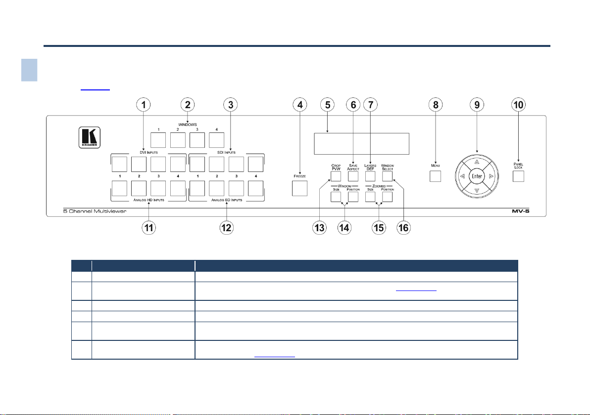
4Defining the MV-5 5 Channel Multiviewer 6
5Installing in a Rack 10
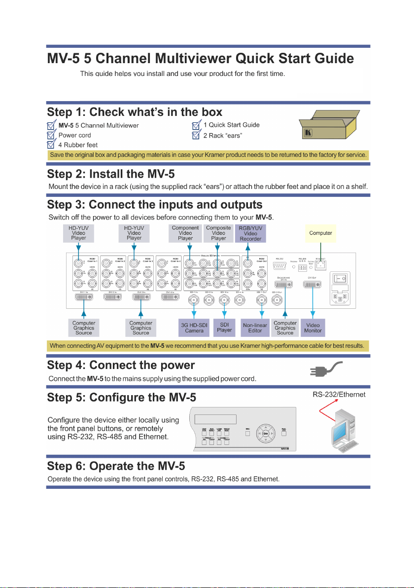
6Connecting the MV-5 5 Channel Multiviewer 11
6.1 Connecting to the MV-5 Using the RS-232 Connection 14
6.2 Connecting to the MV-5 Using the RS-485 Connection 14
6.3 Connecting to the MV-5 Using Ethernet 14
7Configuring and Operating the MV-5 Locally 18
7.1 Configuring the MV-5 Using the Menu 20
7.2 Operating the MV-5 Using the Front Panel Buttons 33
8Configuring and Operating the MV-5 Remotely 43
8.1 The Multiviewer Main Window 44
8.2 The Menu Bar 45
8.3 The Quick Access Toolbar 51
8.4 Using the MV-5 Multiviewer Software 53
9Upgrading the Firmware 60
10 Technical Specifications 61
11 Default Communication Parameters 62
12 Default EDID 63
13 Kramer Protocol 3000 64
13.1 Kramer Protocol 3000 Syntax 64
13.2 Kramer Protocol 3000 Commands 67
Figures
Figure 1: MV-5 5 Channel Multiviewer Front Panel 6
Figure 2: MV-5 5 Channel Multiviewer Rear Panel 8
Figure 3: Connecting the MV-5 5 Channel Multiviewer 12
Figure 4: Local Area Connection Properties Window 15
Figure 5: Internet Protocol Version 4 Properties Window 16
Figure 6: Internet Protocol Properties Window 17
Figure 7: Image Position and Scaling Example 35
Figure 8: MV-5 Controller Software Main Window 44
Figure 9: Background Color Window 46
Figure 10: Image Properties Window 47
Figure 11: Advanced Properties Window 48
Figure 12: Device Details Window 50
Figure 13: About MV-5 Window 51
Figure 14: Quick Access Toolbar 51
Figure 15: Quick Access Toolbar Icons 51

MV-5 - Introduction
1
1 Introduction
Welcome to Kramer Electronics! Since 1981, Kramer Electronics has been
providing a world of unique, creative, and affordable solutions to the vast range of
problems that confront video, audio, presentation, and broadcasting professionals
on a daily basis. In recent years, we have redesigned and upgraded most of our
line, making the best even better!
Our 1,000-plus different models now appear in 11 groups that are clearly defined
by function: GROUP 1: Distribution Amplifiers; GROUP 2: Switchers and Routers;
GROUP 3: Control Systems; GROUP 4: Format/Standards Converters; GROUP 5:
Range Extenders and Repeaters; GROUP 6: Specialty AV Products; GROUP 7:
Scan Converters and Scalers; GROUP 8: Cables and Connectors; GROUP 9:
Room Connectivity; GROUP 10: Accessories and Rack Adapters and GROUP 11:
Sierra Video Products.
Congratulations on purchasing your Kramer MV-5 5 Channel Multiviewer which is
ideal for:
Professional broadcasting and production studios
Presentation applications
Post production

2
MV-5 - Getting Started
2 Getting Started
We recommend that you:
Unpack the equipment carefully and save the original box and packaging
materials for possible future shipment
Review the contents of this user manual
2.1 Achieving the Best Performance
To achieve the best performance:
Use only good quality connection cables (we recommend Kramer high-
performance, high-resolution cables) to avoid interference, deterioration in
signal quality due to poor matching, and elevated noise levels (often
associated with low quality cables)
Do not secure the cables in tight bundles or roll the slack into tight coils
Avoid interference from neighboring electrical appliances that may adversely
influence signal quality
Position your MV-5 away from moisture, excessive sunlight and dust
This equipment is to be used only inside a building. It may only be
connected to other equipment that is installed inside a building.
2.2 Safety Instructions
Caution:
There are no operator serviceable parts inside the unit
Warning:
Use only the power cord that is supplied with the unit
Warning:
Do not open the unit. High voltages can cause
electrical shock! Servicing by qualified personnel only
Warning:
Disconnect the power and unplug the unit from the wall
before installing
!
!

MV-5 - Getting Started
3
2.3 Recycling Kramer Products
The Waste Electrical and Electronic Equipment (WEEE) Directive 2002/96/EC
aims to reduce the amount of WEEE sent for disposal to landfill or incineration by
requiring it to be collected and recycled. To comply with the WEEE Directive,
Kramer Electronics has made arrangements with the European Advanced
Recycling Network (EARN) and will cover any costs of treatment, recycling and
recovery of waste Kramer Electronics branded equipment on arrival at the EARN
facility.
2.4 Accessory to Medical Equipment (IEC 60601-1)
In the modern medical environment remote access is essential, for example, to
transfer clinical data between doctors and to train to medical students. The MV-5 is
certified according to the IEC 60601-1-2, Clause 2.1.3, Medical Electrical
Equipment, Part 1: General Requirements for EMC standard which is required
when accessory devices are used at locations where medical personnel and
patients are present.
The MV-5 constitutes an optional component that can be considered necessary
and suitable as part of medical equipment or for use as part of a medical system to
provide real time simultaneous video feeds to those present at the local medical
environment and at remote locations. In this environment, the MV-5 can be added
to the system ONLY if the connecting equipment has been evaluated and meets
the IEC 60601-1-2 EMC standards. Note, that when attaching accessory devices
to a digital or analog interface, they must comply with the IEC standard for which
they are used: EMC Standard (IEC 60601-1-2), Information Technology equipment
(IEC 60950-1 (2ed)).

4
MV-5 - Overview
3 Overview
The MV-5 is a versatile, high-performance video and graphic multi-viewer for DVI
signals, SD and HD analog signals up to 1920x1200@60Hz, and SDI signals up to
3G HD-SDI. The device can window up to four sources (plus a background) in any
layout and output the image as SDI, DVI, component and composite video signals.
Both preprogrammed and customizable screen division is supported.
In particular, the MV-5 features:
16 inputs with rapid selection and switching
An input bandwidth of up to 3Gbps which supports standard definition, high
definition and 3G high definition serial digital video signals
SMPTE 259M, 292M and 424M input compliance and support for data rates
of 270Mbps, 1.4835Gbps, 1.485Gbps, 2.967Gbps and 2.97Gbps
Input-cable equalization up to 350m (1150ft) for SD signals, 140m (459ft) for
1.5GHz HD signals, and 120m (394ft) for 3GHz HD signals
SD means an NTSC or PAL compatible video format, consisting of 480 (for NTSC) or
576 (for PAL) lines of interlaced video. HD means a video format consisting of 720
active lines of progressive video or 1080 lines of progressive or interlaced video
Any format to any format cross-conversion
Any Standard to any standard cross-conversion
HDCP support on DVI inputs/outputs
Four independent chroma-key engines for each image layer
Window and image scaling, zooming (up to 1000%), and aspect ratio control
Independent layer transparency control
Brightness, contrast, color and sharpness control
Window or input label insertion
Any frozen image capture can be saved in a file (up to four still images
1920x1200)
Recall an image from any file and represent it in any window or background

MV-5 - Overview
5
Image file exchange between MV-5 and a PC application using serial or
Ethernet ports
Loading any synthesized test pattern image
Multi-video output formats; SD-SDI (259M), HD-SDI (292M) and 3G HD-SDI
(SMPTE 424M), HDMI, HD, SD, analog and composite
Kramer re-Klocking™ and equalization on each input—rebuilds the digital
signal to travel longer distances
Flexible control options; front panel with menu LCD, Ethernet and RS-232
Screen handling buttons; freeze, size, position
16 user-definable screen layouts
A front panel lock button
The MV-5 is housed in a 19" 2U rack mountable enclosure and is fed from a
100-240 VAC universal switching power supply.
You can control the MV-5 using the front panel buttons, or remotely via:
RS-232/RS-485 serial commands transmitted by a serial controller (see
Section 6.1 and Section 6.2)
A PC connected to the Ethernet port on the device via a LAN using the
control software (see Section 6.3)

4 Defining the MV-5 5 Channel Multiviewer
Figure 1 defines the front panel of the MV-5.
Figure 1: MV-5 5 Channel Multiviewer Front Panel
#
Feature
Function
1
DVI INPUTS 1~4 Buttons
Press to select one of the DVI sources
2
WINDOWS 1~4 Buttons
Press to make one of the windows the upper-most window (see Section 7.2.1). The order of the other
windows is not changed
3
SDI INPUTS 1~4 Buttons
Press to select one of the SDI sources
4
FREEZE Button
Press to freeze and release the selected window signal
5
LCD 2 Line x 20 Character
Text Display
Displays the current configuration or menu
6
SAVE ASPECT Button
Press to turn on the Save Aspect mode whereby the window or image aspect is locked during size
adjustments (see Section 7.2.1)
6
MV-5 –Defining the MV-5 5 Channel Multiviewer

MV-5 –Defining the MV-5 5 Channel Multiviewer
7
#
Feature
Function
7
LAYERS DEF Button
Press to set the order of priority of the window layers
8
MENU Button
Press to enter the configuration menu. When the menu is displayed, press to exit one level (see
Section 7.1)
9
ENTER Navigation Pad
Press Enter to enter the sub-menu or accept a parameter value. Press and hold together with the
arrow keys to scroll rapidly through parameter values (see Section 7.1)
10
PANEL LOCK Button
Press and hold to lock the front panel buttons. Press and hold again to unlock the front panel buttons
(see Section 7.2.8)
11
ANALOG HD INPUTS 1~4
Buttons
Press to select one of the analog HD sources
12
ANALOG SD INPUTS 1~4
Buttons
Press to select one of the analog SD sources
13
CROP PVW Button
Press to display a full screen preview of the selected window image. Press when zooming to show the
mask of the cropped image
14
WINDOW
Buttons
SIZE Button
Press to adjust the size of the selected window (see Section 7.2.3)
POSITION
Button
Press to adjust the position of the selected window
15
ZOOMED
Buttons
SIZE Button
Press to adjust the image size within the selected window, that is, the degree of zoom
POSITION
Button
Press to adjust the image position within the selected window, that is, the image panorama
16
WINDOW SELECT Button
Press to step through the windows to select an active window to adjust

Figure 2 defines the rear panel of the MV-5.
Figure 2: MV-5 5 Channel Multiviewer Rear Panel
#
Feature
Function
1
RGB BNC Connectors
IN 1
Connect to an analog HD video source
2
IN 2
Connect to an analog HD video source
3
IN 3
Connect to an analog HD video source
4
IN 4
Connect to an analog HD video source
5
ANALOG SD INPUTS BNC Connectors
Connect to up to 12 composite, 6 YC or 3 YUV sources
6
RGB/COMP OUT BNC Connectors
Connect to an analog HD or SD acceptor
7
RS-232 9-pin D-sub Serial Connector
Connect to a PC/serial controller (see Section 6.1)
8
PROGRAM Button
For the use of Kramer service personnel only
9
RS-485 3-pin Terminal Block
Connect to an RS-485 serial controller (see Section 6.2)
10
FACTORY RESET Button
Press while power cycling the device to reset to factory default values (see Section 7.2.9
and Section 11)
11
ETHERNET RJ-45 Connector
Connect to a PC via a LAN (see Section 6.3)
8MV-5 –Defining the MV-5 5 Channel Multiviewer

MV-5 –Defining the MV-5 5 Channel Multiviewer
9
#
Feature
Function
12
DVI IN 1 ~ 4 DVI Connectors
Connect to the DVI video sources (1 to 4)
13
SDI IN 1 ~ 4 BNC Connectors
Connect to the SDI video sources (1 to 4)
14
SDI OUT 1 and 2BNC Connectors
Connect to the SDI video acceptors (1 and 2)
15
BACKGROUND DVI IN Connector
Connect to the DVI background video source (see Section 6)
16
DVI OUT DVI Connector
Connect to the DVI acceptor
17
Mains Power Connector, Fuse and Switch
Plug in the power cord, switch the device on and off

10
MV-5 - Installing in a Rack
5 Installing in a Rack
This section provides instructions for rack mounting the unit.

MV-5 - Connecting the MV-5 5 Channel Multiviewer
11
6 Connecting the MV-5 5 Channel Multiviewer
You can use your MV-5 to switch four of the 16 inputs (four HD, four SD, four DVI,
and four SDI), to four outputs (two SDI, a DVI and an HD). The four inputs are
combined in a customizable format and then combined with a user-selectable
background.
Always switch off the power to all devices before connecting them to
your MV-5. After connecting your MV-5, connect its power and then
switch on the power to each device.
i

MV-5 - Connecting the MV-5 5 Channel Multiviewer
13
2. Connect up to 12 composite, six YC or three YUV SD video sources, (for
example, component and CV composite video players) to the Analog SD
INPUTS BNC connectors.
3. Connect the RGB/Comp OUT BNC connectors to an analog HD or SD video
acceptor, (for example, an RGB/YUV video recorder).
4. Connect up to four DVI sources, (for example, computer graphics sources)
to the DVI In connectors.
5. Connect up to four SDI sources, (for example, a 3G HD-SDI camera and an
SDI player) to the SDI In BNC connectors.
6. Connect the SDI Out BNC connectors to up to two SDI acceptors (for
example, an HD-SDI non-linear editor).
7. Connect a DVI source, (for example, a computer graphics source) to the
Background DVI In connector.
8. Connect the DVI Out connector to a DVI acceptor, (for example, a display).
9. If required, connect a controller to the:
RS-232 port (see Section 6.1)
RS-485 port (see Section 6.2)
Ethernet connector (see Section 6.3)
10. Connect the power cord and power the device on.

14
MV-5 - Connecting the MV-5 5 Channel Multiviewer
6.1 Connecting to the MV-5 Using the RS-232 Connection
You can connect to the MV-5 via an RS-232 connection using, for example, a PC.
Note that a null-modem adapter/connection is not required.
To connect to the MV-5 via RS-232:
Connect the RS-232 9-pin D-sub rear panel port on the MV-5 unit via a
9-wire straight cable (only pin 2 to pin 2, pin 3 to pin 3, and pin 5 to pin 5
need to be connected) to the RS-232 9-pin D-sub port on your PC
6.2 Connecting to the MV-5 Using the RS-485 Connection
6.2.1 Connecting via RS-485
You can operate the MV-5 via the RS-485 port from a distance of up to 1200m
(3900ft) using any device equipped with an RS-485 port (for example, a PC).
To connect a device with an RS-485 port to the MV-5:
Connect the A (+) pin on the RS-485 port of the PC to the A (+) pin on the
RS-485 port on the rear panel of the MV-5
Connect the B (–) pin on the RS-485 port of the PC to the B (–) pin on the
RS-485 port on the rear panel of the MV-5
Connect the G pin on the RS-485 port of the PC to the G pin on the RS-485
port on the rear panel of the MV-5
If you are using shielded cable, connect the shield only to the G pin of
device 1
6.3 Connecting to the MV-5 Using Ethernet
You can connect to the MV-5 via Ethernet using either of the following methods:
Directly to the PC using a crossover cable (see Section 6.3.1)
Via a network hub, switch, or router, using a straight-through cable (see
Section 6.3.2)

MV-5 - Connecting the MV-5 5 Channel Multiviewer
15
6.3.1 Connecting the Ethernet Port Directly to a PC
Youcan connect the Ethernet port of the MV-5 directly to the Ethernet port on your
PC using a crossover cable with RJ-45 connectors.
This type of connection is recommended for identifying the MV-5
with the factory configured default IP address.
After connecting the MV-5 to the Ethernet port, configure your PC as follows:
1. Click Start > Control Panel > Network and Sharing Center.
2. Click Change Adapter Settings.
3. Highlight the network adapter you want to use to connect to the device and
click Change settings of this connection.
The Local Area Connection Properties window for the selected network
adapter appears as shown in Figure 4.
Figure 4: Local Area Connection Properties Window
i

16
MV-5 - Connecting the MV-5 5 Channel Multiviewer
4. Click on Internet Protocol Version 4 (TCP/IPv4) to highlight the selection.
5. Click Properties.
The Internet Protocol Properties window relevant to your IT system appears
as shown in Figure 5.
Figure 5: Internet Protocol Version 4 Properties Window
6. Select Use the following IP Address for static IP addressing and fill in the
details as shown in Figure 6.
You can use any IP address in the range 192.168.1.1 to 192.168.1.255
(excluding 192.168.1.39) that is provided by your IT department.
Table of contents
Other Kramer Media Converter manuals

Kramer
Kramer VM-1610 User manual

Kramer
Kramer PT-1SPDIF User manual

Kramer
Kramer VM-30CA User manual

Kramer
Kramer VP-409 User manual

Kramer
Kramer VP-420 User manual

Kramer
Kramer VP-721DS User manual

Kramer
Kramer FC-113 User manual

Kramer
Kramer VP-434 User manual

Kramer
Kramer VM-50AN User manual

Kramer
Kramer FC-17 User manual

Kramer
Kramer FC-41 User manual

Kramer
Kramer VP-437xl User manual

Kramer
Kramer WP-DEC7 User manual

Kramer
Kramer VP-501x1 User manual

Kramer
Kramer VM-2DH User manual

Kramer
Kramer FC-70R User manual

Kramer
Kramer KDS-USB2 Kit User manual

Kramer
Kramer VP-503XL User manual

Kramer
Kramer VP-472 User manual

Kramer
Kramer 575 User manual