Toptech MultiLoad III User manual

MultiLoad III / RCU III
Explosion Proof (EX) Hardware
(Loaded with MultiLoad II+ / RCU II+ Firmware)
Installation Guide
MAY 26, 2023

2MultiLoad III/RCU III Hardware - Explosion Proof (EX) Installation Guide
TOPTECH SYSTEMS
MultiLoadIII/ RCUIII –ExplosionProof(EX)Hardware
InstallationGuide
(LoadedwithMultiLoadII+/RCUII+Firmware)
1124 Florida Central Parkway
Longwood, FL 32750
USA
Phone +1 (407).332.1774
Copyright Notice
Copyright © 2006 - 2023 Toptech Systems, Inc. All Rights Reserved.
The information contained in this document is proprietary and confidential. No part of this document may be copied, reproduced, or
transmitted in any medium without the express written permission of Toptech Systems, Inc.
Disclaimer
Toptech Systems assumes no responsibility for damages resulting from installation or use of its products. Toptech Systems will not be
liable for any claims of damage, lost data, or lost time as a result of using its products.

3MultiLoad III/RCU III Hardware - Explosion Proof (EX) Installation Guide
EU Declaration of Conformity
The signatory, representing the manufacturer, declares that the products listed below are in conformity with the essential requirements of
the following EC Directive(s) when installed in accordance with the product installation instructions:
2014/32/EU The Measuring Instruments Directive (and its amending directives)
2014/30/EU The Electromagnetic Compatibility Directive (and its amending directives)
2014/34/EU The Potentially Explosive Atmospheres Directive (and its amending directives)
Product: Operator Interface/Process Control Equipment intended for use in potentially explosive
atmospheres
Model name/number: MultiLoad III EX (MID, YES), RCU III EX (MID, NO)
Protective Systems: Flameproof ‘d’, Intrinsic Safety ‘ib’
Notified Body(ies)
Det Norske Veritas Certification AS, Number 0575
NMi Certin B.V., Number 0122
Veritasveien 1
Hugo de Grootplein 1
1322 Høvik, Norway
3314 EG Dordrecht
The Netherlands
Conformity has been demonstrated with reference to the following documentation:
EC type-examination certificate : Presafe 17 ATEX 9557X
IECEx CoC : IECEx PRE 17.0013X
EC type-examination certificate : TC7311
Compliance with the Essential Health and Safety Requirements has been assessed by reference to the following standards:
WELMEC guide 8.8 General and Administrative Aspects of the Voluntary System of Modular Evaluation of Measuring
instruments under MID
OIML R117-1:2007(E) Dynamic measuring systems for liquids other than water
EN 61000-6-4: 2007 Generic emissions for industrial operating environments
EN 61000-6-2: 2005 Generic immunity for industrial operating environments
EN 60079-0: 2012 Electrical apparatus for explosive gas atmospheres—General requirements
EN 60079-1: 2014 Electrical apparatus for explosive gas atmospheres—Flameproof enclosures ‘d’
EN 60079-11: 2012 Electrical apparatus for potentially explosive atmospheres—Intrinsic safety ‘i’
Year of CE Marking: 2023
Name: William J. Porthouse Position: Director of Engineering & Production Date: June 2023
Name Plate

4MultiLoad III/RCU III Hardware - Explosion Proof (EX) Installation Guide
TableofContents
OVERVIEW..................................................................................................................................... 8
CHAPTER 1 GENERAL INFORMATION & WARNINGS ........................................................ 10
Receiving and/or Returning Equipment ........................................................................................... 10
Safety Warnings.................................................................................................................................. 11
Electrostatic Discharge (ESD) Protection ........................................................................................ 13
FCC Note.............................................................................................................................................. 13
CHAPTER 2 OPERATING CONDITIONS AND COMPONENTS............................................. 14
Product Outline and Dimensions ...................................................................................................... 14
MultiLoad III/RCU III EX Hardware Picture................................................................................... 14
MultiLoad III/RCU III EX Hardware Dimensions ........................................................................... 15
2.1.2.1 Front View ..................................................................................................................................... 15
2.1.2.2 Back View...................................................................................................................................... 16
2.1.2.3 Bottom View.................................................................................................................................. 17
2.1.2.4 Top View ....................................................................................................................................... 18
2.1.2.5 Left Side View ............................................................................................................................... 19
2.1.2.6 Right Side View............................................................................................................................. 20
Operating Characteristics .................................................................................................................. 21
CHAPTER 3 INSTALLING THE MULTILOAD III/RCUIII EX HARDWARE ........................ 22
Tools Required.................................................................................................................................... 22
Installation..................................................................................................................................... 22
Servicing and Repair..................................................................................................................... 22
Cover Closure and Bolt Replacement............................................................................................... 22
Cable Entries ....................................................................................................................................... 23
Mounting the MultiLoad III/RCU III EX Hardware Enclosure........................................................... 23
Metal Plate or Rail......................................................................................................................... 23
Wood............................................................................................................................................. 23
Concrete or Cinder Block Walls .................................................................................................... 23
Mounting Height Considerations................................................................................................... 23
Recommended Wire Sizes and Torque for All Terminal Blocks .................................................... 25
Electrical Supply Connections .......................................................................................................... 25
Cable Gland Entries...................................................................................................................... 25
Mains Supply Connection ............................................................................................................. 26
Equipment Grounding ................................................................................................................... 26

5MultiLoad III/RCU III Hardware - Explosion Proof (EX) Installation Guide
Equipment Battery......................................................................................................................... 27
CHAPTER 4 DATA COMMUNICATIONS INTERFACE ........................................................... 28
Available Communications Protocol Selection and Wire Spec ..................................................... 29
Ethernet......................................................................................................................................... 29
RS-422/485................................................................................................................................... 29
RS-232.......................................................................................................................................... 30
Communication Connection Wiring.................................................................................................. 31
Ethernet –Host/TMS Communications......................................................................................... 31
Serial FCM I/ FCM II Communications, COM 0, RS485............................................................... 32
Serial Host/TMS Communications ................................................................................................ 33
4.2.3.1 COM 1 - RS-485 4-wire - Host/TMS Communications ................................................................. 33
4.2.3.2 COM 1 - RS-485 2-wire - Host/TMS Communications ................................................................. 34
4.2.3.3 COM 1 - RS-232 - Host/TMS Communications ............................................................................ 35
Host Ticket Printer/Data Logger.................................................................................................... 35
4.2.4.1 COM3 –RS232 - Host Ticket Printer/Data Logger....................................................................... 36
4.2.4.2 COM3 –RS232 –PTB Protocol Host Ticket Printer/Data Logger................................................ 37
CHAPTER 5 CONNECTING FIELD DEVICES TO INTERNAL FCMS..................................... 38
CHAPTER 6 CONFIGURATIONS ............................................................................................ 39
Weights and Measures Switch Access Control............................................................................... 39
External Switch Access Control (MultiLoad III Hardware Only).................................................... 39
Field Switch Access Control.......................................................................................................... 40
Keypad ................................................................................................................................................. 41
Menus and Screens ............................................................................................................................ 41
Field Modification and Data Entry..................................................................................................... 42
MultiLoad II+/RCU II+ Firmware Preliminary Configuration............................................................ 44
Verifying Communications with FCMs. ............................................................................................ 48
Using I/O Diagnostics......................................................................................................................... 50
CHAPTER 7 SERVICE AND REPAIR....................................................................................... 51
Overview and Subassemblies............................................................................................................ 51
Main Board Replacement ................................................................................................................... 53
Display Subassembly Replacement.................................................................................................. 54
Keypad Barrier Replacement............................................................................................................. 57
Card Reader Replacement ................................................................................................................. 58

6MultiLoad III/RCU III Hardware - Explosion Proof (EX) Installation Guide
FCM Power Supply Replacement ...................................................................................................... 59
Keypad Replacement.......................................................................................................................... 60
Mounting Feet Installation.................................................................................................................. 62
Cover Replacement............................................................................................................................. 63
Overview Parts List and Part Numbers............................................................................................. 66
CHAPTER 8 REVISION HISTORY .......................................................................................... 67
Hardware Revision.............................................................................................................................. 67
Manual Revision.................................................................................................................................. 67

7MultiLoad III/RCU III Hardware - Explosion Proof (EX) Installation Guide
TableofFigures
FIGURE 2.1 MULTILOAD III/RCU III EX HARDWARE 14
FIGURE 2.2 UNIT OUTLINE DRAWING –FRONT VIEW 15
FIGURE 2.3 UNIT OUTLINE DRAWING –BACK VIEW 16
FIGURE 2.4 UNIT OUTLINE DRAWING –BOTTOM VIEW 17
FIGURE 2.5 UNIT OUTLINE DRAWING –LEFT SIDE VIEW 19
FIGURE 2.6 UNIT OUTLINE DRAWING –RIGHT SIDE VIEW 20
FIGURE 3.1 SUGGESTED MOUNTING POSITION 24
FIGURE 3.2 SCREEN VISIBLE AREA 24
FIGURE 3.3 MULTILOAD III/RCU III EX HARDWARE MAIN BOARD POWER CONNECTOR (TB1) 26
FIGURE 3.4 MULTILOAD III/RCU III EX HARDWARE MAIN BOARD BATTERY (BT1) 27
FIGURE 4.1 MULTILOAD III/RCU III EX HARDWARE MAIN BOARD COMMUNICATION CONNECTORS 28
FIGURE 4.2 ETHERNET CONNECTIONS 31
FIGURE 4.3 FCM CONNECTIONS 32
FIGURE 4.4 RS485 4-WIRE, HOST TO A SINGLE MULTILOAD III/RCU III EX HARDWARE (RECOMMENDED) 33
FIGURE 4.5 RS485 4-WIRE, HOST TO MULTIPLE MULTILOAD III/RCU III EX HARDWARE UNITS 33
FIGURE 4.6 RS485 2-WIRE, HOST TO A SINGLE MULTILOAD III/RCU III EX HARDWARE UNIT 34
FIGURE 4.7 RS485 4-WIRE, HOST TO MULTIPLE MULTILOAD III/RCU III EX HARDWARE UNITS 34
FIGURE 4.8 RS232, HOST TO A SINGLE MULTILOAD III/RCU III EX HARDWARE UNIT 35
FIGURE 4.9 RS232, HOST TO MULTIPLE MULTILOAD III/RCU III EX HARDWARE UNITS 35
FIGURE 4.10 TICKET PRINTER / DATA LOGGER CONNECTIONS WITH HANDSHAKE 36
FIGURE 4.11 TICKET PRINTER / DATA LOGGER CONNECTIONS WITHOUT HANDSHAKE 36
FIGURE 4.12 PTB PRINTER CONNECTION WITH HANDSHAKE 37
FIGURE 4.13 PTB PRINTER CONFIGURATION 37
FIGURE 6.1 W&M BOLT SWITCH 40
FIGURE 7.1 MULTILOAD III / RCU III EX HARDWARE UNIT 51
FIGURE 7.2 SUBASSEMBLY IDENTIFICATION 52
FIGURE 7.3 MAIN BOARD ASSEMBLY REMOVAL 53
FIGURE 7.4 DISPLAY ASSEMBLY REMOVED FROM THE MOUNTING BRACKET 55
FIGURE 7.5 REMOVAL OF KEYPAD BARRIER 57
FIGURE 7.6 EXPLODED VIEW OF CARD READER 58
FIGURE 7.7 REMOVAL OF FCM POWER SUPPLY 59
FIGURE 7.8 KEYPAD ASSEMBLY INSTALLATION PREP 61
FIGURE 7.9 MOUNTING FEET ASSEMBLY 62
FIGURE 7.10 DISCONNECT DISPLAY AND KEYPAD CABLES 63
FIGURE 7.11 INSTALL TOP RIGHT SCREW AND REMOVE LOWER HINGE KNUCKLE. 64
FIGURE 7.12 REMOVE TOP RIGHT SCREW AND LIFT COVER OFF. 65

8MultiLoad III/RCU III Hardware - Explosion Proof (EX) Installation Guide
Overview
This document is designed to guide individuals installing MultiLoad III/RCU III EX Hardware equipment,
engineering firms developing site electrical drawings, and users troubleshooting system operations such as
managers, system administrators, technicians, andmeter proving personnel.
The following table provides an informative summary of the material available in this guide:
Chapter
Topics Covered
1.General Information and Warnings
This chapter reviews safety and compliance information, as well as
instructions for receiving and returning products.
2.Operating Conditions & Components
This chapter covers product outlineand dimensions, as well as
operating characteristics of the unit.
3.Installing the MultiLoad III/RCU III EX
Hardware
This chapter covers installation considerations and instructions for
the MultiLoad III/RCU III EX Hardware.
4.Data Communication Interface
This chapter reviews hardware connections andcommunication
processes.
5.Connecting Field Devices to the
Internal I/O Board
This chapter covers the available I/O points per board, the
terminal arrangements per board, and then describes in detail
how to connect different field devices to the internal I/O Board.
6. Configurations
This chapter describes how to navigate the system, select field
values, perform data entry, and toggle options on and off.
7. Service and Repair
This chapter describes how to service and repair the MultiLoad
III/ RCU III EX Hardware subassemblies and parts.
8. Hardware Revision History &
Compatibility
This chapter provides changes, modifications,and updates to the
hardware.
9. Revision History
This chapter provides further hardware revisions as well as revisions
made to this document.

9MultiLoad III/RCU III Hardware - Explosion Proof (EX) Installation Guide
The following keys allow the user to locate information needed in this guide:
ICON KEY
Important information to enhance understanding and make better use of the product.
Indicates potential damage to hardware or loss of data.
Potential for property damage or that personal injury may occur. Pay close attention and
follow instructions when this symbol is displayed.
Typographical Conventions:
Boldface: Indicates what is pressed on the keypad. Example: Key in 00000.
Italics: Emphasizes a key product or industry term.
Example: the display features a pick-list style of item selection.
This guide covers RCU III/MultiLoad III EX Hardware installation information only. For information about
base MultiLoad firmware, please consult the MultiLoad II+ Firmware User Guide. For information about base
RCU firmware, please consult the RCU II+ Firmware User Guide. For information about wiring other models,
please consult the respective installation guides. For information about the MultiLoad register interface and
Modbus communication, please reference the MultiLoad II Communication Guide. Updated versions of all
manuals, including this one, are available on our website at http://www.toptech.com.

CHAPTER 1–GENERAL INFORMATION & WARNINGS
10 MultiLoad III/RCU III Hardware - Explosion Proof (EX) Installation Guide
Chapter 1 General Information & Warnings
Receiving and/or Returning Equipment
At receipt, the MultiLoad III/ RCU III EX Hardware should be immediately inspected after opening the
packaging case. If any damage is visible, notify the carrier at once to establish liability.
Contact Toptech’s Return Materials Department to initiate timely repair or replacement of the unit.
A Return Materials Authorization (RMA) will be for the purpose of returning the product or parts
requiring repair. Do not return any material to Toptech without an RMA.
Contact Information for Americas:
Return Materials Department
Toptech Systems, Inc.
1124 Florida Central Pkwy
Longwood, FL 32750 USA
+1 (407) 332-1774
Contact Information for EMEA and Asia:
Return Materials Department
Toptech System NVs
Nieuwe weg 1- haven 1053
2070 Zwijndrecht, BELGIUM
+32 (0)3 250 60 60
Chapter
1

CHAPTER 1–GENERAL INFORMATION & WARNINGS
11 MultiLoad III/RCU III Hardware - Explosion Proof (EX) Installation Guide
Safety Warnings
NORTH AMERICAN INSTALLATIONS:
▲This equipment is suitable for use in Class I, Division 1, Groups C and D locations, OR non-
hazardous locations.
▲WARNING: TO REDUCE THE RISK OF IGNITION OF HAZARDOUS ATMOSPHERES,
conduit runs must have a sealing fitting connected within 18 inches of the enclosure.
▲WARNING: TO REDUCE THE RISK OF IGNITION OF HAZARDOUS ATMOSPHERES,
disconnect from the supply circuit before opening enclosure. Keep tightly closed when
circuits are live.
▲WARNING: Substitution of components may impair intrinsic safety.
▲WARNING: Do not open when an explosive gas atmosphere is present.
▲WARNING: All unused conduit entries must be sealed with a conduit plug which
satisfies the flameproof “d” method of protection.
▲CAUTION: Battery may explode if mistreated. DO NOT RECHARGE, DISASSEMBLE, OR
DISPOSE OF IN FIRE.
▲CAUTION: Field wiring must have a temperature rating of +75 °C or greater. Use copper
wire only.
▲Consult installation manual for required cable entry size and thread.
▲A battery is installed into the main board for retention of time and date only. This battery should
last more than ten years. This battery can be replaced by the end user but must be
replaced with Matsushita Electric, model BR2032 only. Use of another battery may
present a risk of fire or explosion.
▲The installation of this product must be in conformity with NFPA 70 (US National Electric Code)
or CSA C22.1 (Canadian Electrical Code) as appropriate.
INSTALLATIONS NORD-AMÉRICAINES (FRANÇAIS)
▲Cet équipement est compatible pour une installation en Classe I, Division 1, Groupes C & D ou
les emplacements non dangereux.
▲AVERTISSEMENT: RISQUE D'EXPLOSION Les scellements des conduits doit être
installé à moins de 18 pouces du boîtier.
▲AVERTISSEMENT: RISQUE D'EXPLOSION Couper le courant avant d'enlever le
couvercle. Garder le couvercle bien fermé tant que les circuits sont sous tension.
▲AVERTISSEMENT: La substitution de composants peut compromettre la sécurité
intrinsèque.
▲AVERTISSEMENT: Ne pas ouvrir si une atmosphère explosive peut être présente.
▲AVERTISSEMENT: Toutes les entrées du boîtier inutilisées doivent être scellées avec un
bouchon de conduit.
▲PRUDENCE: La pile peut exploser si elle est maltraitée. NE PAS RECHARGER, NE PAS
DÉMONTER, ET NE PAS JETER DANS LE FEU.
▲PRUDENCE: Câblage de terrain doit avoir un classement de température de +75 °C ou
plus. Utilisez uniquement du fil de cuivre.
▲Consultez le manuel d'installation pour le filetage de forme et la taille du presse-étoupe.
Suite à la page suivante

CHAPTER 1–GENERAL INFORMATION & WARNINGS
12 MultiLoad III/RCU III Hardware - Explosion Proof (EX) Installation Guide
INSTALLATIONS NORD-AMÉRICAINES (FRANÇAIS, suite de la page précédente)
▲Une batterie est installée dans la carte principale pour la conservation de l'heure et de la date
uniquement. Cette batterie devrait durer plus de dix ans. Cette batterie peut être remplacée
par l'utilisateur final mais doit être remplacée par Matsushita Electric, modèle BR2032
uniquement. L'utilisation d'une autre batterie peut présenter un risque d'incendie ou
d'explosion.
▲L’installation de ce produit doit se conformer avec NFPA 70 ou CSA C22.1 comme appropriée.
ATEX AND IECEX INSTALLATIONS:
▲This equipment is suitable for use in Ex Zone I Group IIB locations or non-hazardous locations.
THE LETTER “X” TO THE RIGHT OF THE CERTIFICATE NUMBER INDICATES THE
FOLLOWING SPECIAL CONDITIONS FOR SAFE USE:
▲CERTAIN FLAMEPROOF JOINTS ARE OTHER THAN THE MINIMUM OR MAXIMUM
DIMENSIONS GIVEN IN IEC/EN/BR 60079-1, CLAUSE 5. PLEASE CONSULT TOPTECH
SYSTEMS IF DIMENSIONAL INFORMATION IS REQUIRED.
▲MAXIMUM SPECIFIED GAP OF FLANGE JOINT IS 0.08mm.
▲AMBIENT TEMPERATURE RANGE IS BETWEEN -40°C AND +60°C.
▲CAUTION: COVER BOLTS MUST HAVE A YIELD STRESS OF AT LEAST 700 N/mm².
▲WARNING: TO REDUCE THE RISK OF IGNITION OF HAZARDOUS ATMOSPHERES,
disconnect from the supply circuit before opening enclosure. Keep tightly closed when
circuits are live.
▲WARNING: Substitution of components may impair intrinsic safety.
▲WARNING: Do not open when an explosive gas atmosphere is present.
▲WARNING: All unused conduit entries must be sealed with a conduit plug which
satisfies the flameproof “d” method of protection. Blanking elements must be removable
with the aid of a tool, ATEX certified, suitable for Gas Group IIB and suitable for an
ambient temperature range of -40 C to +60 C.
▲CAUTION: Battery may explode if mistreated. DO NOT RECHARGE, DISASSEMBLE, OR
DISPOSE OF IN FIRE.
▲CAUTION: Field wiring must have a temperature rating of +75 °C or greater. It must also
have a temperature rating for the lowest expected minimum ambient temperature. Use
copper wire only.
▲Consult installation manual for required cable entry size and thread.
▲A battery is installed into the main board for retention of time and date only. This battery should
last more than ten years. This battery can be replaced by the end user but must be
replaced with Matsushita Electric, model BR2032 only. Use of another battery may
present a risk of fire or explosion.
▲The installation of this product must be in conformity with IEC/EN/BR 60079-14.

CHAPTER 1–GENERAL INFORMATION & WARNINGS
13 MultiLoad III/RCU III Hardware - Explosion Proof (EX) Installation Guide
Electrostatic Discharge (ESD) Protection
The MultiLoad III/ RCU III EX Hardware contains electronic components and assemblies subject to
damage by ESD. The MultiLoad III/ RCU III EX Hardware was designed to protect against ESD while
the unit is closed and in normal operation. Proper handling procedures must be observed during the
removal, installation, repair and other handling of printed circuit board assemblies, electronic devices,
and components. This includes:
1) Service to be performed by authorized personnel only.
2) The person performing the service must be grounded by an ESD grounding strap and
connected to ground.
3) While performing maintenance or repair, touch an unpainted metal of the MultiLoad III/RCU
III EX Hardware surface prior to touching or handling any printed circuit boards or electronic
components.
4) Printed circuit board assemblies must be placed in and transported in conductive bags or
other conductive containers.
5) Printed circuit boards must not be removed from the conductive container until time of use.
6) All other “best” practices for protecting devices from ESD must be observed.
FCC Note
This equipment complies with the limits for a Class A Digital Device, pursuant to part 15 of the FCC
Rules. These limits are designed to provide reasonable protection against harmful interference when
the equipment is operated in a commercial environment. This equipment generates, uses, and can
radiate radio frequency energy and, if not installed and used in accordance with the instruction manual,
may cause harmful interference to radio communications. Operation of this equipment in a residential
area is likely to cause harmful interference in which case the user will be required to correct the
interference at their expense.
Modifications not approved by the manufacturer could void the user's authority to operate the
equipment under FCC rules.

CHAPTER 2–OPERATING CONDITIONS AND COMPONENTS
14 MultiLoad III/RCU III Hardware - Explosion Proof (EX) Installation Guide
Chapter 2 Operating Conditions and Components
Product Outline and Dimensions
MultiLoad III/RCU III EX Hardware Picture
Figure 2.1 MultiLoad III/RCU III Ex Hardware
Chapter
2
CHAPTER 2–OPERATING CONDITIONS AND COMPONENTS
15 MultiLoad III/RCU III Hardware - Explosion Proof (EX) Installation Guide
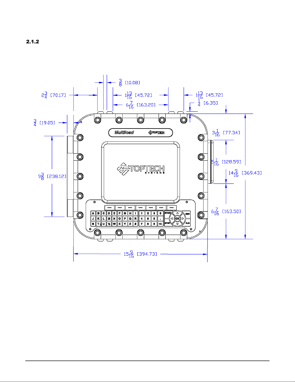
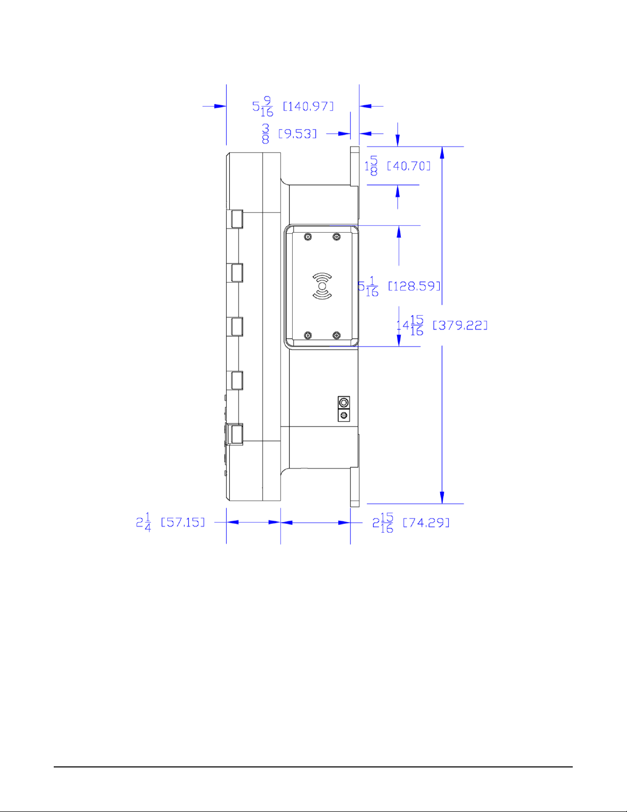
MultiLoad III/RCU III EX Hardware Dimensions
The dimensions in this section are indicated in inches and millimeters (in parenthesis).
2.1.2.1 Front View
Figure 2.2 Unit Outline Drawing –Front View
CHAPTER 2–OPERATING CONDITIONS AND COMPONENTS
16 MultiLoad III/RCU III Hardware - Explosion Proof (EX) Installation Guide
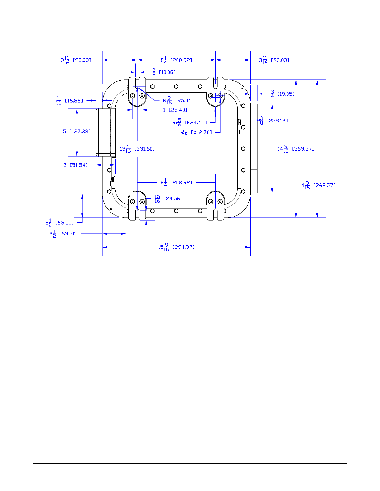
2.1.2.2 Back View
Figure 2.3 Unit Outline Drawing –Back View

CHAPTER 2–OPERATING CONDITIONS AND COMPONENTS
17 MultiLoad III/RCU III Hardware - Explosion Proof (EX) Installation Guide
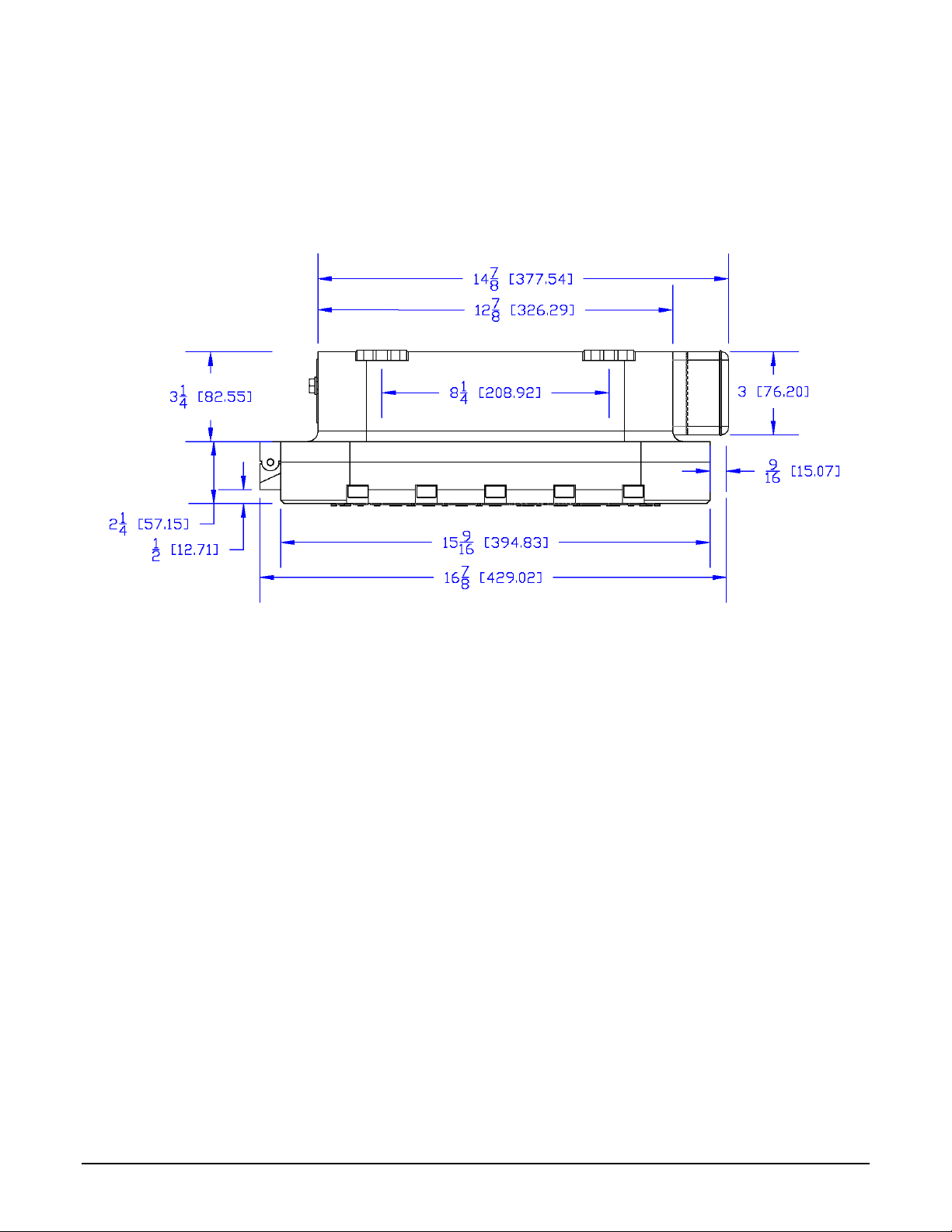
2.1.2.3 Bottom View
Figure 2.4 Unit Outline Drawing –Bottom View
CHAPTER 2–OPERATING CONDITIONS AND COMPONENTS
18 MultiLoad III/RCU III Hardware - Explosion Proof (EX) Installation Guide
2.1.2.4 Top View
Unit Outline Drawing –Top View
CHAPTER 2–OPERATING CONDITIONS AND COMPONENTS
19 MultiLoad III/RCU III Hardware - Explosion Proof (EX) Installation Guide
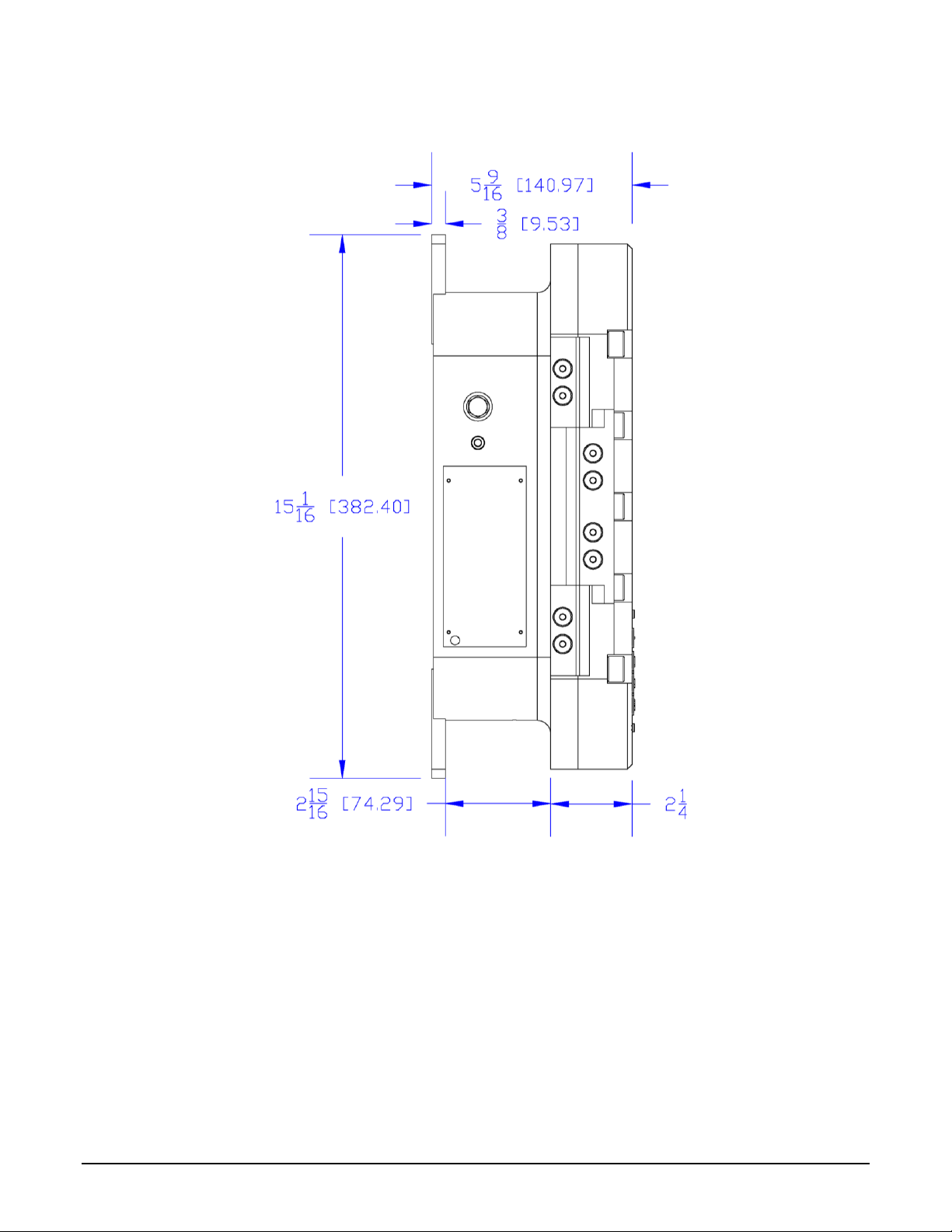
2.1.2.5 Left Side View
Figure 2.5 Unit Outline Drawing –Left Side View
CHAPTER 2–OPERATING CONDITIONS AND COMPONENTS
20 MultiLoad III/RCU III Hardware - Explosion Proof (EX) Installation Guide
2.1.2.6 Right Side View
Figure 2.6 Unit Outline Drawing –Right Side View
Other manuals for MultiLoad III
1
This manual suits for next models
1
Table of contents
Other Toptech Industrial Equipment manuals


Popular Industrial Equipment manuals by other brands

Bosch
Bosch Rexroth MTA 200 Planning Manual

Aerotech
Aerotech PRO190LM Hardware manual

KMT
KMT STREAMLINE SL-V SRP 100 Operation and maintenance manual

Conductix-Wampfler
Conductix-Wampfler Safe-Lec 2 manual

Dustcontrol
Dustcontrol S 11000 EX Translation of the original instructions

LNS
LNS Alpha ST320 S2 instruction manual


