Toptech MultiLoad II User manual

M
Mu
ul
lt
ti
iL
Lo
oa
ad
d
I
II
I
M
Mo
ob
bi
il
le
e
Installation Guide
Version C
April 6, 2012

2
MultiLoad II Mobile Installation Guide: Version C
Electrical Considerations
!
A battery is soldered to the CPU board and provides nonvolatile data storage and time/date retention. This
battery should last between ten and thirteen years and is a factory replaceable part. This battery must be
replaced with Matsushita Electric, model BR2477A only. Use of another battery may present a risk of fire or
explosion.
!
CAUTION: Battery may explode if mistreated. DO NOT RECHARGE, DISASSEMBLE, OR DISPOSE OF IN FIRE.
Copyright Notice
Copyright © 2006 - 2012 Toptech Systems, Inc.
The information contained in this document is proprietary and confidential. No part of this document may be copied, reproduced, or
transmitted in any medium without the express written permission of Toptech Systems, Inc.
Disclaimer
Toptech Systems assumes no responsibility for damages resulting from installation or use of its products. Toptech Systems will not be liable
for any claims of damage, lost data, or lost time as a result of using its products.
Toptech
Systems, Inc.
A Unit of IDEX Corporation
logo is a registered trademark of Toptech Systems, Inc.
TMS™, TMS5™, TMS6™, RCU II Remote Control Unit™, Toptech MultiLoad II™, MultiLoad II -RCU™, FCM Flow Control Module™
are trademarks of Toptech Systems, Inc.
Copyright © 2007-2012 Toptech Systems, Inc. All Rights Reserved.

3
MultiLoad II Mobile Installation Guide: Version C
Table of Contents
CHAPTER 1General.......................................................................................................................................... 5
1.1Who Should Use This Guide................................................................................................................... 5
1.2Information Alerts:................................................................................................................................... 5
1.2.1Typographical Conventions:.................................................................................................................. 5
1.2.2Receiving and/or Returning Equipment:................................................................................................ 5
1.3Operating Characteristics:...................................................................................................................... 6
1.4Electrostatic Discharge (ESD) Protection:............................................................................................ 7
1.5Recommended Wire Sizes And Torque For All Terminal Blocks....................................................... 8
CHAPTER 2Installing the MultiLoad II Mobile............................................................................................... 9
2.1Tools Required......................................................................................................................................... 9
2.1.1Installation.............................................................................................................................................. 9
2.1.2Servicing and Repair ............................................................................................................................. 9
2.2Mounting the MultiLoad II Mobile Enclosure........................................................................................ 9
2.3Electrical Supply Connections............................................................................................................... 9
2.3.1Cable Entries......................................................................................................................................... 9
2.3.2Attaching vehicle power....................................................................................................................... 10
CHAPTER 3Data Communications Interface............................................................................................... 11
3.1Communications Protocol Selection and Connection:..................................................................... 12
3.1.1RS-422/485:......................................................................................................................................... 12
3.1.2RS-232................................................................................................................................................. 12
3.1.3Ethernet ............................................................................................................................................... 17
CHAPTER 4I/O Configuration ....................................................................................................................... 18
4.1Mass Meter and Solenoid Valve Connections.................................................................................... 20
4.2MultiLoad II Flow Meter and Control Valve Wiring............................................................................. 21
4.3MultiLoad II RTD Temperature Probe Wiring...................................................................................... 22
4.4MultiLoad II 4-20mA Input Wiring......................................................................................................... 23
4.5MultiLoad II 2 Output Air Eliminator Wiring........................................................................................ 24
CHAPTER 5Modem Configuration................................................................................................................ 25
5.1Accessing The Administrative Interface............................................................................................. 25
5.2Configuring Port Forwarding................................................................................................................ 26
Configuring Trusted Networks ......................................................................................................................... 27
CHAPTER 6MultiLoad Configuration........................................................................................................... 28
6.1Overview................................................................................................................................................. 28
6.2Navigating the System:......................................................................................................................... 28
6.2.1Menus and Screens............................................................................................................................. 28
6.2.2Field Modification and Data Entry........................................................................................................ 29
6.3Network Setup........................................................................................................................................ 31
6.4RCU General Setup................................................................................................................................ 33
6.5Suggested Setup for TDS ..................................................................................................................... 34
6.5.1Network Configuration......................................................................................................................... 34
6.5.2RCU General Configuration................................................................................................................. 35
CHAPTER 7Troubleshooting ........................................................................................................................ 36
7.1Modular Design:..................................................................................................................................... 36
7.1.1Operating the Flat Display Cable Connectors:.................................................................................... 37
7.1.2CPU Subassembly Removal and Replacement:................................................................................. 39
7.1.3Display Subassembly Removal and Replacement:............................................................................. 40
7.1.4Keypad Removal and Replacement:................................................................................................... 40
7.1.5Prox Reader Removal and Replacement:........................................................................................... 40

4
MultiLoad II Mobile Installation Guide: Version C
Table of Figures
Figure 1.1MultiLoad II Terminal Block Recommended Wire Size and Screw Torque....................................... 8
Figure 2.1 MultiLoad II Mobile DC Power Supply/Comm Board....................................................................... 10
Figure 3.1RS485 4-Wire, Host to a Single MultiLoad II/ RCU II (recommended) ........................................... 13
Figure 3.2RS485 4-Wire, Host to Multiple MultiLoad II/ RCU IIs..................................................................... 13
Figure 3.3RS485 2-Wire, Host to a Single MultiLoad II/ RCU II...................................................................... 14
Figure 3.4RS485 4-Wire, Host to Multiple MultiLoad II/ RCU IIs..................................................................... 14
Figure 3.5RS232, Host to a Single MultiLoad II/ RCU II.................................................................................. 15
Figure 3.6RS232, Host to Multiple MultiLoad II/ RCU IIs................................................................................. 15
Figure 3.7Ticket Printer / Data Logger Connections with Handshake............................................................. 16
Figure 3.8Ticket Printer / Data Logger Connections without Handshake........................................................ 16
Figure 3.9Ethernet Connections...................................................................................................................... 17
Figure 4.1 I/O Board Terminal Block Assignments........................................................................................... 19
Figure 4.2I/O Board Field Wiring: Flow Meter and Control Valve.................................................................... 20
Figure 4.3MultiLoad II Digital/ Analog I/O Board Field Wiring: Flow Meter and Control Valve........................ 21
Figure 4.4MultiLoad II Digital/ Analog I/O Board Field Wiring: RTD................................................................ 22
Figure 4.5MultiLoad II Digital/ Analog I/O Board Field Wiring: 4-20mA Input.................................................. 23
Figure 4.6MultiLoad II Digital/ Analog I/O Board Field Wiring: 2 Output Air Eliminator................................... 24
Figure 5.1Status screen................................................................................................................................... 25
Figure 5.2Port forwarding configuration........................................................................................................... 26
Figure 5.3Trusted IP range configuration ........................................................................................................ 27
Figure 7-1Cam lock in the Open (Up) position................................................................................................. 37
Figure 7-2Display Cable Insertion.................................................................................................................... 38
Figure 7-3Cam lock in the closed (down) position........................................................................................... 38
Figure 7.4Microprocessor Board...................................................................................................................... 41
Figure 7.5Power Supply Board........................................................................................................................ 41
Figure 7.6I/O Board.......................................................................................................................................... 42
Figure 7.7Power Supply / Comm Board & I/O Board Chassis ........................................................................ 43
Chapter 1 – General 5
MultiLoad II Mobile Installation Guide: Version C
!
CHAPTER 1 GENERAL
1.1 WHO SHOULD USE THIS GUIDE
This guide is intended for individuals installing MultiLoad II equipment, engineering firms developing site electrical
drawings, and users troubleshooting system operation such as managers, system administrators, technicians,
and meter proving personnel.
1.2 INFORMATION ALERTS:
Important information to enhance understanding and make better use of the product.
Indicates potential damage to hardware or loss of data.
Potential for property damage or that personal injury may occur. Pay close attention and follow
instructions when you see this symbol.
1.2.1 TYPOGRAPHICAL CONVENTIONS:
Boldface: Indicates what you are to press on the keypad. Example: Key in 00000.
Italics: Emphasizes a key product or industry term.
Example: the display features a pick list style of item selection.
1.2.2 RECEIVING AND/OR RETURNING EQUIPMENT:
The MultiLoad II should be immediately inspected after opening the packaging case. If any damage is visible
notify the carrier at once to establish liability. Contact Toptech Account Management to initiate timely repair or
replacement of the unit.
Account Management will issue a Return Materials Authorization (RMA) to return the product or parts requiring
repair. Do not return any material to Toptech without an RMA.
Account Management contact information:
Account Management
Toptech Systems
1124 Florida Central Pkwy
Longwood, FL
(407) 332-1774
Prior to installation the MultiLoad II should be stored in its packing case and be protected from damage due to
handling and adverse weather conditions.

Chapter 1 – General 6
MultiLoad II Mobile Installation Guide: Version C
1.3 OPERATING CHARACTERISTICS:
Operating voltage: 9-30Vdc, 1.2A
Operating temperature: -22°F to 140°F (-25°C to 60°C).
with Optional Heater: -40°F to 140°F (-40°C to 60°C).
Enclosure: Type 4
Weight: 24 lbs (11 kg)
Display: Color 5.7” Diagonal VGA
Prox Card Reader: Captive or Non-captive
Optional Lockable External Switches: Program Access, Weights & Measures Parameter Access
Keypad: 47 Key Alpha/ Numeric Capacitive Keypad
Communications:
3 serial ports (1 RS-232, 1 RS-485, 1 User Selectable RS-232 or RS-485)
1 Ethernet port 10/100 Mbps
Internal I/O: The quantity and electrical ratings of the I/O are described in the table below.
TYPE I/O QUANTITY,LOCATION ELECTRICAL RATING
DC Outputs: 7 (TB1, TB2) 0 - 30Vdc, 1.0A (per point)
DC Inputs: 6 (TB6, TB7)
(2 High Speed) 5 – 30Vdc
Dual Channel flow meter inputs (1-5000Hz)
Miscellaneous signal inputs
12Vdc Source: 167mA Max Load (TB5) Isolated Power Supply
Power for flow meter pulsers or preamps
RTD Input: 1 (TB3) 100ohm platinum, four wire
Coefficient 0.00385Ohm/Ohm/°C
Analog Input 1 (TB4 pins 1 &.2) 4 – 20mA, 1.5V maximum burden
Analog Output 1 (TB4 pins 3 - 6) 4 – 20mA, Requires 12Vdc – 30Vdc Supply

Chapter 1 – General 7
MultiLoad II Mobile Installation Guide: Version C
1.4 ELECTROSTATIC DISCHARGE (ESD) PROTECTION:
The MultiLoad II contains electronic components and assemblies subject to damage by ESD. The MultiLoad II
was designed to protect against ESD while the unit is closed and in normal operation. Proper handling
procedures must be observed during the removal, installation, repair and other handling of printed circuit board
assemblies, electronic devices and components to include:
1) Service to be performed by authorized personnel only.
2) The person performing the service must be grounded by an ESD grounding strap and connected to
ground.
3) While performing maintenance or repair, touch an unpainted metal of the MultiLoad II surface prior to
touching or handling any printed circuit boards or electronic components.
4) Printed circuit board assemblies must be placed in and transported in conductive bags or other
conductive containers.
5) Printed circuit boards must not be removed from the conductive container until time of use.
6) All other “best” practices for protecting devices from ESD must be observed.
Chapter 1 – General 8
MultiLoad II Mobile Installation Guide: Version C
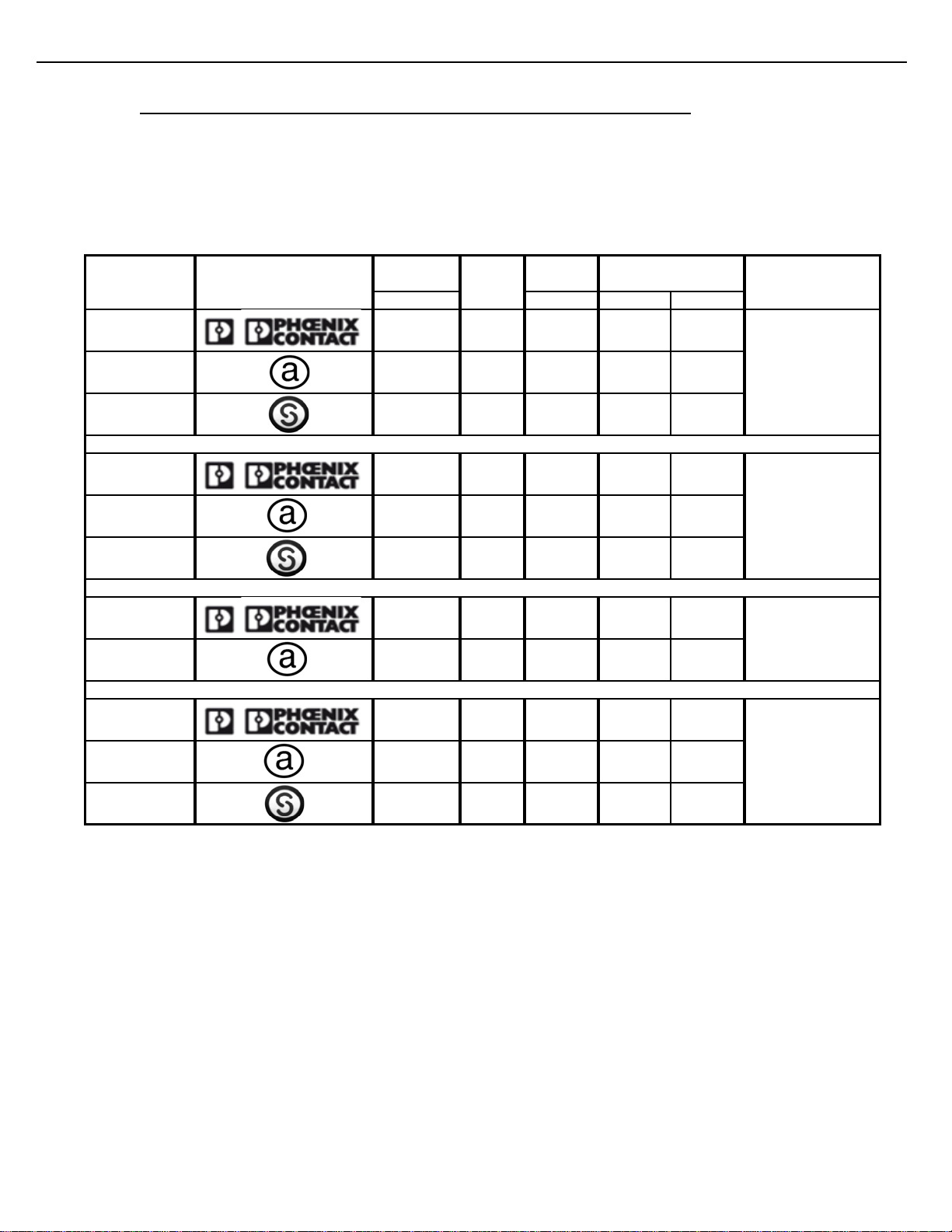
1.5 RECOMMENDED WIRE SIZES AND TORQUE FOR ALL TERMINAL BLOCKS
Three sizes of terminal blocks are used in the MultiLoad II products: 7.62 mm pitch (supply power), 5.08 mm pitch
(line voltage switching), and 3.81 mm pitch (serial communication, analog or dc voltages). All sizes, orientations,
and manufacturer brands have different torque and wire size specifications. Please follow the recommendations
in Figure 2.1 below. The manufacturer may be determined by looking for the logo molded into the terminal block,
usually on the side.
[mm] [AWG] [Nm] [LB in]
Phoenix 7.62 Straight 30 - 12 .6 - .8 5 - 7
On-Shore
Technology 7.62 Straight 24 - 12 0.40 3.5
Sauro 7.62 Straight 30 - 12 0.8 7
Phoenix 5.08 Straight 30 - 12 .6 - .8 5 - 7
On-Shore
Technology 5.08 Straight 24 - 12 0.40 3.5
Sauro 5.08 Straight 30 - 12 0.8 7
Phoenix 3.81 Straight 30 - 14 0.5 4
On-Shore
Technology 3.81 Straight 28 - 16 0.19 1.7
Phoenix 3.81 90° 30 - 14 0.2 - 0.5 2 - 4
On-Shore
Technology 3.81 90° 26 - 16 0.3 3
Sauro 3.81 90° 30 - 14 0.31 2.7
TB2A, TB2B, I/O
Board
Manufacturer Orienta-
tion
Logo Recommended
Screw Torque Location
TB1, Power Supply
Board
TB1, I/O Board
Terminal
Block Pitch
A
llowable
Wire Size
TB2 - TB5, Power
Supply Board; TB3
-
TB6, I/O Board
Figure 1.1 MultiLoad II Terminal Block Recommended Wire Size and Screw Torque

Chapter 2 – Installing the MultiLoad II Mobile 9
MultiLoad II Mobile Installation Guide: Version C
CHAPTER 2 INSTALLING THE MULTILOAD II MOBILE
2.1 TOOLS REQUIRED
2.1.1 INSTALLATION
- ¼” Flat Head screw driver is required for tightening cover screws
2.1.2 SERVICING AND REPAIR
- #2 Philips screwdriver for circuit board removal
- ¼” socket wrench for CPU circuit board removal, 5/16” socket wrench for display board removal
- #2 Philips screwdriver for removal of keypad plat screws
2.2 MOUNTING THE MULTILOAD II MOBILE ENCLOSURE
The MultiLoad II Mobile is designed with a standard 100mm VESA pattern. This enables it to attach to a variety
of vehicle mounting hardware.
2.3 ELECTRICAL SUPPLY CONNECTIONS
2.3.1 CABLE ENTRIES
A variety of cable entries are provided:
Five ½” NPT glands on the right side (use these for power entry, and truck mounted control devices)
Two PG16 glands on the bottom side (use these for modem and GPS connection)
Two ½” NPT glands on the bottom side (use these for in cab mounted devices)
Three ½” NPT glands on the back side (use these for power entry, and truck mounted control devices).
Using the supplied rubber sealing washer a recommended torque of 192 inch-ounces (1 ft-lb.) should be
used on glands or hole plugs as specified by the manufacture.
Note that RJ45 latching plugs can be inserted through the PG16 glands. A service loop is recommended
for all wires and cables entering the enclosure.
Do not allow service loop cables to overlap the circuit boards. Coil any cable length in the
bottom of the enclosure. Keep AC wiring separated from all other wiring in the enclosure by use of
the supplied partitions (see wire partition instructions below.
Chapter 2 – Installing the MultiLoad II Mobile 10
MultiLoad II Mobile Installation Guide: Version C
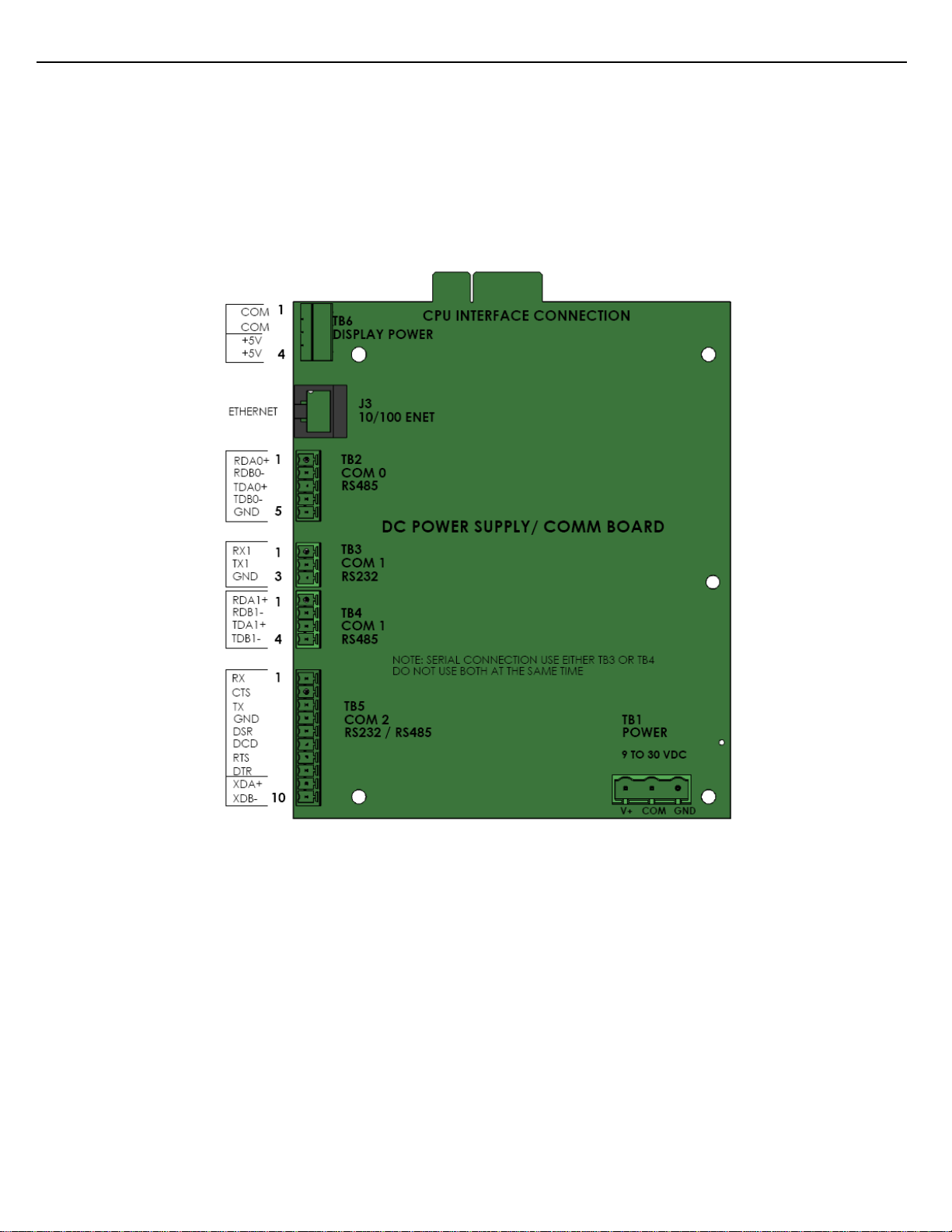
2.3.2 ATTACHING VEHICLE POWER.
Connect red and black wire pairs to the left and center pins of TB1 respectively. This terminal block is located on
the power supply board shown. Connection of the red wire to the accessory voltage is recommended over wiring
to the battery in order to prevent battery drain while the vehicle is not running.
The required power is 9 -30Vdc, 1.2A.
Figure 2.1 MultiLoad II Mobile DC Power Supply/Comm Board

Chapter 3 – Data Communications Interface 11
MultiLoad II Mobile Installation Guide: Version C
CHAPTER 3 DATA COMMUNICATIONS INTERFACE
The MultiLoad II Mobile has four communications ports (see Figure 2.1) each with a specific purpose. The
following section provides the information required to select and make the wiring connections to the ports.
Communication Port Interface Type Typical Function Terminal (Figure 2.1)
Comm. Port 0 RS-485 Internal I/O board /
FCM I / FCM II / PCM
Communication
TB2
Comm. Port 1 RS-232 or RS-485 Host Communication
(TMS) TB3 RS-232
TB4 RS-485
Comm. Port 2 RS-232 Ticket Printer/Data
Logger TB5
Ethernet 10/100MBPS Host Communication
(TMS) J3
Cat 5 Cable
If a service loop is used, the maximum wire length in the service loop should not exceed 3 inches
[75mm].
Separate AC and DC wiring by at least 3 inches [75mm]. Do not allow excess wire in the service
loop to overhang printed circuit board.

Chapter 3 – Data Communications Interface 12
MultiLoad II Mobile Installation Guide: Version C
3.1 COMMUNICATIONS PROTOCOL SELECTION AND CONNECTION:
3.1.1 RS-422/485:
RS-422/485 communications protocol is designed for multi-point (i.e. computer to multiple devices, also called
multi-dropped) communications up to 4,000 feet (1,220 Meters).
RS-422 requires 4-wires (2 twisted pair) for full duplex communications and utilizes a transmit pair of wires (TDA
& TDB) and a receive pair of wires (RDA & RDB).
RS-485 requires 2-wires (1 twisted pair) for half duplex communications and utilizes a single pair of wires
(TDA/RDA & TDB/RDB) for transmit and receive.
This manual will typically refer to both RS-422 and RS-485 as simply RS485 2 wire or RS485 4 wire.
Although a ground wire is not required, the common mode voltage between the MultiLoad II/ RCU
II and the field device must be within -7Vdc to 12Vdc. To correct situations where this is not the
case, the DC common is available on COM 0 and COM 1 by using TB2, pin five (revision 1.1
Power Supply/Comm boards only) and TB 3, pin three. Connect the MultiLoad II/ RCU II DC
common to the signal ground of the field device.
Wire used must meet the following characteristics:
24 AWG stranded.
4-wire, two twisted pair with overall shield.
2-wire, one twisted pair with overall shield.
30pF maximum between conductors.
1,000 ohm impedance.
Maximum length: 4,000 feet (1,220 Meters)
Maximum stub length: 15 feet.
All exposed shields must be properly insulated to prevent short circuits.
All shields must be continuous, soldered, and properly insulated.
3.1.2 RS-232
RS-232 protocol is designed for point-to-point (i.e., computer to a single device) communications limited to 50 feet
requiring a minimum of 3 wires – transmit, receive and ground. Additional wires are required for hardware
handshaking when using printers and data loggers.
Wire used must meet the following characteristics:
24 AWG.
3 conductor with overall shield (data only) or 8 conductor with overall shield (full handshaking).
30 pF maximum between conductors.
Chapter 3 – Data Communications Interface 13
MultiLoad II Mobile Installation Guide: Version C
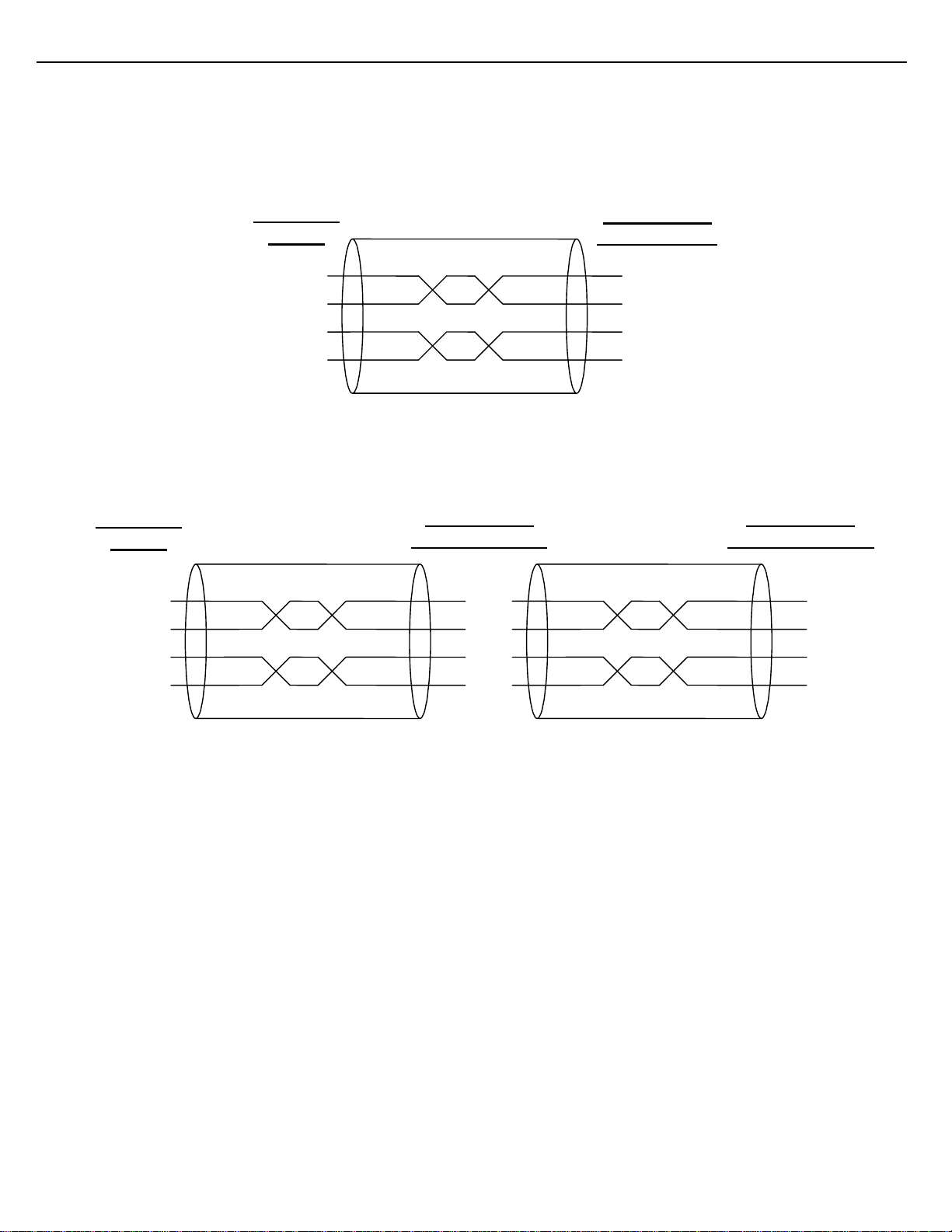
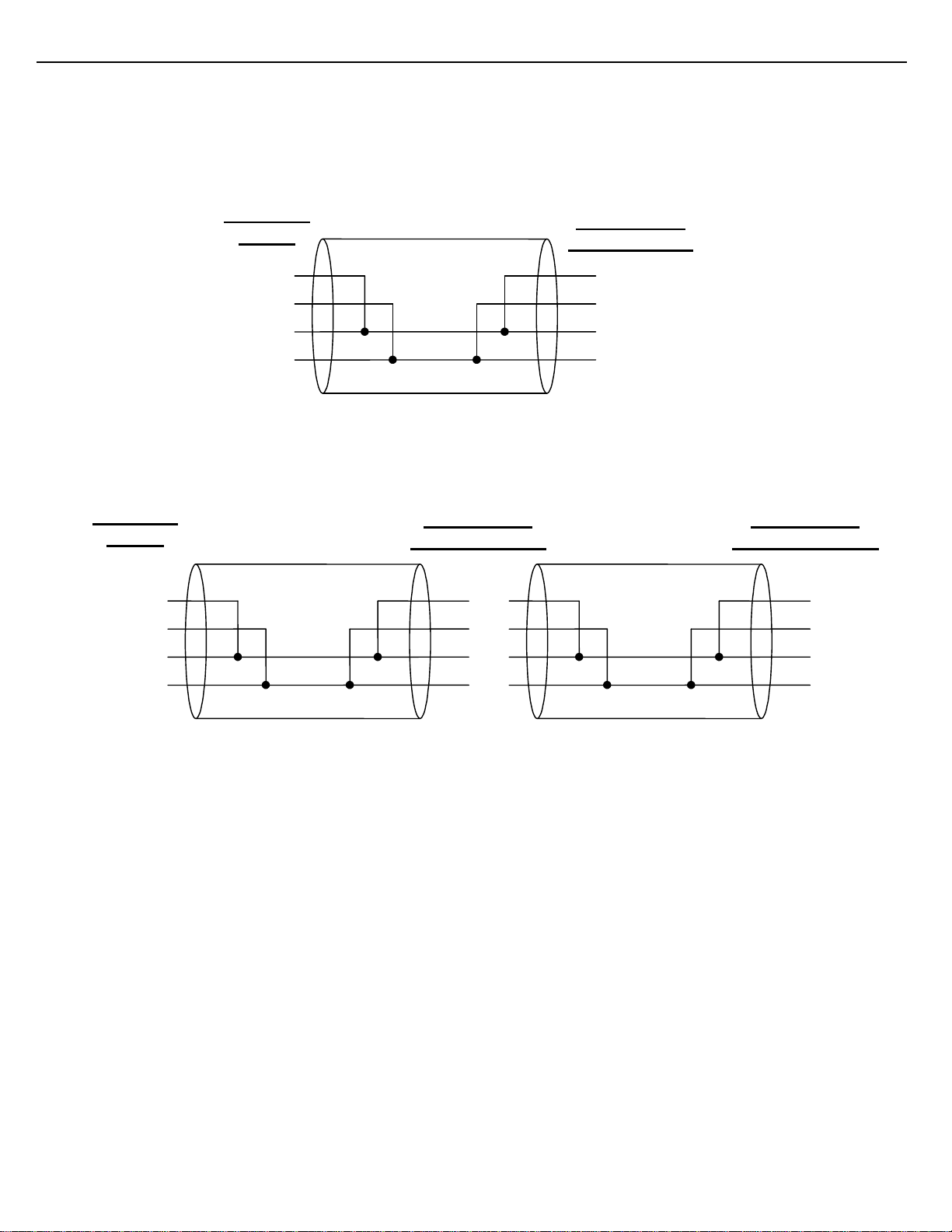
Host/TMS Communications (COM 1 - RS-485 4-wire)
The Host/TMS Computer System can be connected to the MultiLoad II/ RCU II via RS485 4-wire on COM 1.
The TD and RD pairs are swapped at the Host/TMS.
Figure 3.1 RS485 4-Wire, Host to a Single MultiLoad II/ RCU II (recommended)
Figure 3.2 RS485 4-Wire, Host to Multiple MultiLoad II/ RCU IIs
TDA
TDB
RDA
RDB
RDA
RDB
TDA
TDB
RDA
RDB
TDA
TDB
TDA
TDB
RDA
RDB
RDA
RDB
TDA
TDB
Host/TMS
RS485
MultiLoad II/
RCU II #1 COM
Host/TMS
RS485 MultiLoad II/
RCU II #n COM 1
MultiLoad II/
RCU II COM 1
Chapter 3 – Data Communications Interface 14
MultiLoad II Mobile Installation Guide: Version C
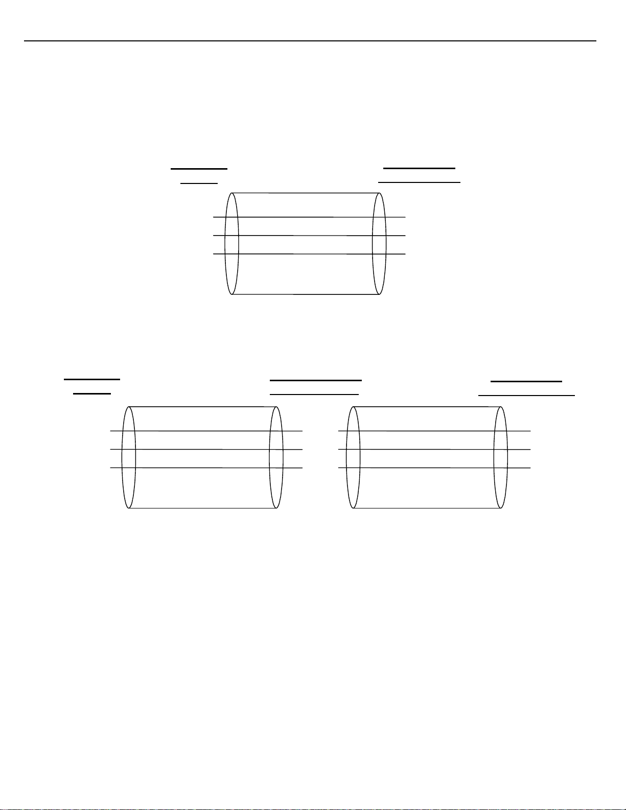
Host/TMS Communications (COM 1 - RS-485 2-wire)
The Host/TMS Computer System can be connected to the MultiLoad II/ RCU II via RS485 2-wire on COM 1.
The TD and RD pairs tied together at the Host/TMS and all MultiLoad II/ RCU IIs.
Figure 3.3 RS485 2-Wire, Host to a Single MultiLoad II/ RCU II
Figure 3.4 RS485 4-Wire, Host to Multiple MultiLoad II/ RCU IIs
TDA
TDB
RDA
RDB
RDA
RDB
TDA
TDB
RDA
RDB
TDA
TDB
TDA
TDB
RDA
RDB
RDA
RDB TDA
TDB
MultiLoad II/
RCU II COM 1
Host/TMS
RS485
MultiLoad II/
RCU II #1 COM
Host/TMS
RS485 MultiLoad II/
RCU II #n COM 1
Chapter 3 – Data Communications Interface 15
MultiLoad II Mobile Installation Guide: Version C
Host/TMS Communications (COM 1 - RS-232)
The Host/TMS Computer System can be connected to the MultiLoad II/ RCU II via RS232 on COM 1.
The TX and RX are swapped at the Host/TMS.
MultiLoad II/ RCU II has the ability to multi-drop onto a RS232 line.
Figure 3.5 RS232, Host to a Single MultiLoad II/ RCU II
Figure 3.6 RS232, Host to Multiple MultiLoad II/ RCU IIs
TX
RX RX
TX
GND GND
RX
TX
GND
TX
RX RX
TX
GND GND
MultiLoad II/
RCU II COM 1
Host/TMS
RS232
MultiLoad II
/
RCU II #1 COM
Host/TMS
RS232 MultiLoad II/
RCU II #n COM 1

Chapter 3 – Data Communications Interface 16
MultiLoad II Mobile Installation Guide: Version C
Host Ticket Printer/Data Logger (COM 2 - RS-232)
A Ticket Printer or Data Logger can be connected to the MultiLoad II/ RCU II via RS232 on COM 2.
The TX and RX are swapped at the MultiLoad II/ RCU II.
Handshake lines MUST be connected or terminated or a Printer Error will be reported.
MultiLoad II/ RCU II will monitor CTS, DSR and DCD for active signals.
Figure 3.7 Ticket Printer / Data Logger Connections with Handshake
Figure 3.8 Ticket Printer / Data Logger Connections without Handshake
MultiLoad II/
RCU II COM 2 Printer Logger RS232
DB25 Connector
RX
CTS
TX
GND
DSR
DCD
RTS
DTR
MultiLoad II/
RCU II COM 2 Printer Logger RS232
DB25 Connector
RX
CTS
TX
GND
DSR
DCD
RTS
DTR
2 - TX
20 - DTR
3 - RX
7 – GND
4 – RTS
5 – CTS
6 – DSR
8 - DCD

Chapter 3 – Data Communications Interface 17
MultiLoad II Mobile Installation Guide: Version C
3.1.3 ETHERNET
Ethernet wiring standard T568B - Cat5 cable (or greater).
Figure 3.9 illustrates the required connections for Ethernet.
The Ethernet controller on revision 2.0 CPU boards uses HP Auto-MDIX technology. By automatically detecting
the signaling on the connected device, the transceiver will configure the port settings automatically. Thus, the
choice of a straight through or cross over cable no longer has to be made—either will work.
1 White/org 1
7 White/Brown
6 Green
5 White/Blue
4 Blue
3 White/Grn
2 Org
8 Brown
6
7
8
5
4
3
2
Twisted Pairs
Figure 3.9 Ethernet Connections
8 - DCD

Chapter 4 – I/O Configuration 18
MultiLoad II Mobile Installation Guide: Version C
CHAPTER 4 I/O CONFIGURATION
The I/O board is mounted above the Power Supply/Comm board. The I/O board is connected to the Power
Supply/Comm board at J4 & J5. Corresponding connections are on bottom side of the I/O board.
The following defines the electrical ratings of Inputs and Outputs supported by the I/O board:
TYPE I/O QUANTITY,LOCATION ELECTRICAL RATING
DC Outputs: 7 (TB1, TB2) 0 - 30Vdc, 1.0A (per point)
DC Inputs: 6 (TB6, TB7)
(2 High Speed) 5 – 30Vdc
Dual Channel flow meter inputs (1-5000Hz)
Miscellaneous signal inputs
12Vdc Source: 167mA Max Load (TB5) Isolated Power Supply
Power for flow meter pulsers or preamps
RTD Input: 1 (TB3) 100ohm platinum, four wire
Coefficient 0.00385Ohm/Ohm/°C
Analog Input 1 (TB4 pins 1 &.2) 4 – 20mA, 1.5V maximum burden
Analog Output 1 (TB4 pins 3 - 6) 4 – 20mA, Requires 12Vdc – 30Vdc Supply

Chapter 4 – I/O Configuration 19
MultiLoad II Mobile Installation Guide: Version C
Figure 4.1 I/O Board Terminal Block Assignments
7 DC Outputs
0 – 30Vdc
0.6A
No orientation on pins.
RTD.
Analog Input
Analog Output
12Vdc, 2W supply
Available for pulsers
6 DC Inputs:
5-30Vdc

Chapter 4 – I/O Configuration 20
MultiLoad II Mobile Installation Guide: Version C
4.1 MASS METER AND SOLENOID VALVE CONNECTIONS
MASS
METER
Pulse
1
6
Terminal
Number
Pulse GND
Density +
Density -
1
6
Terminal
Number
I+ 1
I- 2
V+ 3
GND 4
I5
6
TB4
4-20
mA IN
4-20
mA
OUT
+-
12/24Vdc
DCCom
In
6
Out
5
In
4
Out
3
In
2
Out
1
Port 0
Port 1
Port 2
TB2
Note: For Density and pulse
wiring, use a 24AWG twisted
pair shielded for each pair.
+
1
-
2
+
3
-
4
+
5
-
6
Port 4
Port 5
Port 6
TB6
Note: Largest wire that TB1 – TB7 can accommodate is 16AWG.
Terminal
Number
1
6
+
-
+
-
12Vdc Coil
(Air Valve)
TO CHASSIS
12/24Vdc (J1.3 PS)
12Vdc Coil
(Interposing
Relay
Figure 4.2 I/O Board Field Wiring: Flow Meter and Control Valve
Other manuals for MultiLoad II
1
Table of contents
Other Toptech Industrial Equipment manuals


