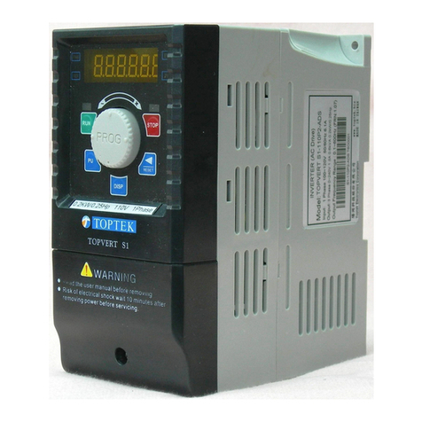
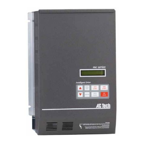
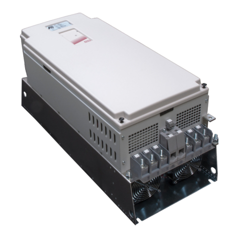
TOPTEK TOPVERT E1 Series User manual

ISO 9001:2008
高性能 向量控制 變頻器
High performance Vector Control AC drive
TOPTEK ELECTRONICS CORPORATION
QUICK START
快速安裝手冊

TOPVERT G1/H1/P1 Series
E-1
PREFACE
Thank you for choosing TOPTEK’S TOPVERT G1, H1 and P1 Series Drive. TOPVERT G1, H1 and
P1 Series are Sensorless current vector control high-performance drive. They were manufactured by
adopting high-quality components, material and incorporating the latest microprocessor technology
available.
Copyright statement
All information in this Quick start manual are Toptek’s intellectual property. Even we had done our best
to make this manual but is unable to guarantee 100% correct.Based on " Never Stop for better but
perfect accomplished " quality policy, our product permanently in the journey which perfectly strives for
perfection to the pursue,Therefore we reserve the right to change the information in this manual
without prior notice.But we will continue the latest edition document in our website, for free download.
http://www.toptek.biz
Getting Started
This manual will be helpful in the installation, parameter setting, troubleshooting, and daily
maintenance of the drives. To guarantee safe operation of the equipment, read the following safety
guidelines before connecting power to the drives. Keep this operating manual handy and distribute to
all users for reference.
Always read this manual thoroughly before using TOPVERT G1,H1 and P1 Series drives.
DANGER!
1- AC input power must be disconnected before any maintenance. Do not connect or disconnect
wires and connectors while power is applied to the circuit. Maintenance must be performed by
qualified technicians.
2- A charge may still remain in the DC-link capacitor with voltages even if the power has been turned
off. To avoid personal injury, please ensure that power has turned off before operating drive and
wait ten minutes for capacitors to discharge to safe voltage levels.
3- The drive may be destroyed beyond repair if incorrect cables are connected to the input/output
terminals. Never connect the drive output terminals U/T1, V/T2, and W/T3 directly to the AC main
circuit power supply
CAUTION!
1- There are highly sensitive MOS components on the printed circuit boards. These components are
especially sensitive to static electricity. To avoid damage to these components, do not touch
these components or the circuit boards with metal objects or your bare hands.
2- Ground the drive using the ground terminal. The grounding method must comply with the laws of
the country where the drive is to be installed. Refer to Basic Wiring Diagram.
3- The final enclosures of the drive must comply with EN50178. (Live parts shall be arranged in
enclosures or located behind barriers that meet at least the requirements of the Protective Type
IP20.The top surface of the enclosures or barrier that is easily accessible shall meet at least the
requirements of the Protective Type IP40). (TOPVERT G1, H1 and P1 Series correspond with
this regulation.)
4- Heat sink may heat up over 70℃(158℉), during the operation. Do not touch the heat sink.
5- The rated voltage for the drive must be ≤240V (≤480V for 460V models, ≤600VFor 575V models)
and the mains supply current capacity must be ≤5000A RMS (≤10000A RMS for the ≥40hp
(30kW) models).
6- The leakage current between chassis and earth could be up to 22mA.
7- The load motor should meet IEC:60034-1 standard.
W A R N IN G

TOPVERT G1/H1/P1 Series
E-2
Nameplate Information
Example for G1 series, 3HP/2.2kW 230V 3-Phase,a speed feedback PG card equipped.
Model Explanation
Explanation of Production control data
Please contact the dealers immediately if any discrepancy occurred.
Firmware version : 3.08
Input Specifications
Output Specifications
Barcode
Production control data
Output Frequency Range
Model number
CE certification
G1-232P2-D101-08 T0509001
Model:TOPVERT G1-232P2-D101
(FRN:3.08)
Production Month: 1~9 = Jan. to Sep.
O=Oct. N=Nov. D=Dec.
Production Year: 0~9=2010~2019
Production Factory: T = Taiwan factory
Option Code or custom-made code
Model: G1 series, 230V 3 Phase 2.2kW / 3Hp
Motor V/F selecting Preset (Pr0-02)
Production Number
G1
-
232P2-xxxx-08 T
0
5
09001
Applicable Motor (4 Pole)
(Base on 230V,380V,575V)
0P4= 0.4kW 0P7= 0.75kW
2P2= 2.2kW 5P5= 5.5kW
7P5= 7.5kW 011= 11kW
022= 22kW 075= 75kW
160= 160kW 630= 630kW
Toptek’s AC drive family
AC Power source
21= 230V 1 Phase
23= 230V 3 Phase
43= 460V 3 Phase
63= 575V 3 Phase
G1 series
Hardware version
Blank: original version
A: version A
B: version B
Z: version Z
Brake chopper option
Blank or N : Brake chopper not include
D: Brake chopper built-in
**Brake chopper as standard equipped in
Frame code A & B
Extension, Interface cards & other option
Blank or N : no option
01 :TEK-PG-01 speed feedback card equipped
02 :PU-02 equipped
03 :PU-03 equipped
Enclosure Protection
Blank or N : Standard
0 : IP 00 ( NEMA 0)
1 : IP 20 ( NEMA 1)
2 : IP 21 ( NEMA 4)
**IP 20 (NEMA 1) as standard In
Frame code A , B & C
TOPVERT G1-23 2P2 x-x x xx

TOPVERT G1/H1/P1 Series
E-3
STANDARD SPECIFICATIONS
Series TOPVERT G1 series
High performance general
purpose multi-function drive
TOPVERT H1 series
High performance high speed drive
TOPVERT P1 series
High performance variable torque drive
for Fan & Pump
Control Characteristics
Output frequency range 0.1 - 600Hz, Programmable 0.1 - 6000Hz, Programmable 0.1 - 600Hz, Programmable
Overload endurance 150% of rated current for 1 minute/10 minutes, Ta <=40, 200% of
rated current for 2 seconds
125% of rated current for 1 minute/10
minutes,
Ta <=40,165% of rated current for 2 seconds
Maximum output voltage Proportional to Input Voltage, 3-Phase output
Power factor/Efficiency Power factor no lower than 0.95. Efficiency no lower than 95% at full load
Control system SPWM (Sinusoidal Pulse Width Modulation) vector control, 4 control modes :V/F, V/F + PG, SVC & VC + PG
Speed control range V/F mode 20:1; V/F+PG mode 120:1; SVC mode 120:1; VC+PG mode 600:1
Output frequency resolution Analog input: 10Bit(1/1024), Digital input: 0.01Hz, Fly-Shuttle dial input: 0.01Hz
Output frequency accuracy Analog input: Within ±0.2% of max. output frequency (25℃±10℃).
Digital input: Within 0.01% of set output frequency
PWM carrier Frequency 0.7 -18kHz,Adjustable (Some models are limited), H1: 1.4kHz ~ 36kHz,Adjustable
Torque characteristics auto-torque boost, auto-slip compensation; starting torque can be 150% at 1.0Hz
Skip frequency Setting range 0.00 -600Hz (H1series: 0.00 ~ 6000 Hz), Max. 6 points, skip width are adjustable
Accel/Decel time 0.1-60000 seconds ( 2 Independent settings for Accel/Decel Time)
Stall prevention 0 to 250% of Rated Current, independent adjustable both in acceleration and constant speed operation.
DC Braking DC Braking both when start up and stop , Braking Current Level: 0 to 125% of rated output current. Braking time: 0
to 60 seconds. Braking Start-Point when stop: 0.1-600Hz (H1series: 0.00 ~ 6000 Hz)
Dynamic braking Braking torque Approx. 20%(10%E.D.). Dynamic Brake chopper built-in in Frame code: xx-Aand xx-B.
Others can be built-in as an option. All models can connect to external Dynamic Brake Unit (TDBU-xxxx series).
V/F Pattern 2 of adjustable Random V/F curve. Constant Torque curve & Reduced Torque curve are available.
O
PERATING
Characteristics
Frequency Setting
Keypad
By an Encoder style Fly-Shuttle dial. (setting resolution 0.01Hz/0.1Hz/1Hz/10Hz adjustable)
External
Signal 0 ~ +10VDC((Input impedance 20kΩ), -10 ~ +10VDC((Input impedance 10kΩ),4 ~20mADC ((Input impedance
250Ω),Multi-Function Inputs 1 ~ 6 (15 Steps Jog, up/down), PLC run, RS-485 port MODBUS protocol
Operation Setting
Keypad
Set by RUN, STOP and JOG. Switch-able between Keypad and External signal
External
Signal 2 wire control(FWD/STOP、REV/STOP、RUN/STOP、FWD/REV), 3 wire control, FWD, REV, MI1 to MI6 can be
combined to offer various modes of operation, RS-485 serial interface MODBUS protocol
Multi-Function Digital Input
(DI)
(6 terminals)
Multi-step selection 0 to 15, first to second accel/decel switches, accel/decel inhibit, Input the counter, Pause Stop,
EF Input, Emergency Stop, auxiliary motor control is invalid,ACI/AVI/AUI speed command selection, Reset, PLC
Run, Jog, Up/Down command, Sink/Source selection, Parameter team selection…etc, up to 43 functions.
Multi-Function Output Indication
(DO)
(4 indications )
Include a form C relay contact, a form A relay contact and 2 Open collector output. They can be programmed to
below indications: Drive Operating, FrequencyAttained, zero speed, Base Block, Over torque,
Fault Indication, Local/Remote indication, PLC Operation indication, andAuxiliary Motor Output, Drive ready for
use, IGBT over-heat indication …etc, up to 63 functions.
Multi-Function Analog Input
(AI) AVI: 0 ~ +10VDC((Input impedance 20kΩ), AUI: -10 ~ +10VDC((Input impedance 10kΩ), ACI: 4 ~20mA DC ((Input
impedance 250Ω). 3 different Input terminals can be programmed to 15 functions
Multi-Function Analog Output
(AO) IncludeACO andAVO, They can be programmed to Proportional to output frequency, output current, voltage,
frequency command or motor's speed …etc, up to 15 functions.
Fault Indication The output will be activated when faults occur (User may get 1 or up to 4 indications from below terminals:2 Relay
contact point RA, RB, RC. or 2 Open-collector
Communication function RS-485 serial port, MODBUS protocol, ASCII & RTU. (Baud rate up to 125 k bps)
Other Functions
PID feedback control, Flying start, Automatic voltage regulation (AVR), 2 accel./decel time selection , Auto-optimu
m
accel./decel. Time, S-curves, External fault interlock, External fault reset, Auto Restart after fault, 16 Fault records,
Automatic energy–saving, Upper/Lower limit, Programmable pulse output, Password protection, Pump and Fan
process control, Sleep/Wakeup function , Auto-Tuning, By-Pass, Y-Delta control,. Bi-Directional Speed search,
Reverse inhibit, Automatic torque boost & slip compensation, 16-
step PLC run, 16 step preset speed, Coast or ramp
to stop, Random V/F curve, Mechanical brake release control, IGBT/ Heatsink temperature display & Pre-warning,
Quiet operation mode (No noise), User define Multi-function display, Over torque detection, Over current/voltage t
stall prevention, Sink/Source (NPN/PNP) mode, Electronic Thermal Relay, Internal Counter,
DC injection brake both
in start and stop, Dynamic brake, Controlled cooling Fan, Removable keypad operator, Programmable
Multi-Function DI,DO,AI,AO and Ry terminals.
Intelligent Protection Functions
Self-testing,AC source Over Voltage, Phase loss, Over Voltage, Over Current, Under Voltage, Over Torque,
External Fault, Motor over-load, IGBT Over-temperature, Heat-sink Over-temperature, Electronic thermal, Ground
Fault, Output short circuit, Stall Prevention, Fuse protection, IGBT short circuit , Drive Over Load ,
DC bus capacitor
life monitoring, Auto carrier frequency adjust according temperature, 16 Trip records, Run information of
latest Fault
such like DC-BUS voltage, Output voltage/Frequency/Current, Command frequency, IGBT temperature, Heat-sink
temperature….etc.
Digital Keypad
(PU-02 Digital Keypad with copy
function and PU-03 Digital Keypad
with LCD display are available as an
option)
Eight Function keys: Access R un, Stop, Reset/ Digit Shift, Forward/ Reverse run, Display mode, Keypad Enable,
Programming data and Jog operation…etc.
One Encoder style Fly-Shuttle dial: Sets the parameter number and changes the numerical data
One 6 digits 7 segment display: Display the Setting frequency/actual operation frequency, Output
current/Voltage, motor speed, Fault trip User defined unit(up to 88 type)…etc.
Six LED Display for status indication: Display the Drive run/stop status, Forward/Reverse run status, Keypad
enable, and Frequency command source.
One RJ-45 connector: Removable Keypad, remote control distance up to 150 meters.
Environment
Certificate Complies with CE (EN61800-3) standard
Temperature Ambient: -10 ~ +40 /(℃ ℃ -10 ~ + 50 ) (℃ ℃ Non-Condensing and not frozen). Storage: -20 ~ +60℃ ℃
Humidity Below 98%R.H. (Non-Condensing)
Vibration Below 20Hz: 1G, above 20Hz: 0.6G
Installation Location Altitude 1,000 m or lower, keep away from corrosive gasses, liquid and dust
* All series in TOPVERT family are designed and manufactured base on CNS and IEC, IEEE, CE & UL standard.

TOPVERT G1/H1/P1 Series
E-4
TOPVERT G1, H1 Series
:
1-Phase
,200/
-
15% ~ 240/+10%Vac, 47 ~ 63Hz /[400Hz]
Model Applicable Motor
(230V 4 P) Rated Output Source
Enclosure structure
TOPVERT
G1-xxxxx
H1-xxxxx
Power
(kW)
Horse
Power
(Hp)
Capacity
(kVA)
Current
(A)
Voltage
(V)
Frequency
(Hz)
Current
(Amax.)
Cooling
Method
(Noise
level)
Degree of
protection
Net
Weight
(kg)
Frame
Code
210P4 0.4 0.5 1.2 3 3- Phase,
0-100%
of supply
voltage
G1 series
0 ~ 600
H1 series
0 ~ 6000
5.7 Fan-
cooled
(<70
dB/1M)
IP 20
NEMA 1
[IP
21/40/42
/50/52
Optional]
2.6
G1-A
H1-A
210P7 0.75 1 2 5 9.5 2.7
211P5 1.5 2 3 7.5 14 2.7
212P2 2.2 3 4.4 11 21 3.0
TOPVERT G1, H1 Series
:
3-Phase
, 200/
-
15% ~ 240/+10%Vac, 47 ~ 63Hz /[400Hz]
Model Applicable Motor
(230V 4 P) Rated Output Source
Enclosure structure
TOPVERT
G1-xxxxx
H1-xxxxx
Power
(kW)
Horse
Power
(Hp)
Capacity
(kVA)
Current
(A)
Voltage
(V)
Frequency
(Hz)
Current
(Amax.)
Cooling
Method
(Noise
level)
Degree of
protection
Net
Weight
(kg)
Frame
Code
230P4 0.4 0.5 1.2 3
3- Phase,0-100% of supply voltage
G1 series
:
0 ~ 600
H1 series
:
0 ~ 6000
3.3
Fan-
cooled
(<70
dB/1M)
IP 20
NEMA 1
[IP 21/40/
42/50/52
Optional]
2.6
G1-A
H1-A
230P7 0.75 1 2 5 5.5 2.8
231P5 1.5 2 3 7.5 8.3 2.8
232P2 2.2 3 4.4 11 12 2.8
233P7 3.7 5 6.8 17 19 3.0
235P5 5.5 7.5 10 25 28 3.2
237P5 7.5 10 13 33 36 4.0 G1-B
H1-B
23011 11 15 20 49 54 11.9
G1-C
H1-C
23015 15 20 26 65 72 12.3
23018 18.5 25 30 75 83 13.0
23022 22 30 36 90 99 13.5
23030 30 40 48 120 132 IP 00
NEMA 0
[IP 20/21
/40/42/
50/52
NEMA 1
Optional]
32.7
G1-D
H1-D
23037 37 50 58 145 160 33.8
23045 45 60 73 182 200 34.6
G1-E
23055 55 75 92 232 255 58.0
G1-F
H1-F
23075 75 100 120 300 330 59.4
23090 90 125 143 360 396 Fan-
cooled
(<80
dB/1M)
192
G1-G
23110 110 150 175 440 484 192
23132 132 175 207 520 572 198
23132S 132 175 207 520 572 302
G1-H
Free-st
anding
[ ]: Optional

TOPVERT G1/H1/P1 Series
E-5
TOPVERT G1, H1 Series
:
3-Phase
380/-15% ~ 480/+10%Vac, 47 ~ 63Hz /[400Hz]
Model Applicable Motor
(4 pole) Rated Output Source
Enclosure structure
TOPVERT
G1-xxxxx
H1-
xxxxx
380/415 V
(kW/Hp )
440/460 V
(kW/Hp )
Capacity
(kVA) Current
(A)
Voltage
(V)
Frequency
(Hz)
Current
(A)
Cooling
Method
(Noise
level)
Degree of
protection
Net
Weight
(kg)
Frame
Code
430P7 0.75/1 2.4 3
3- Phase,0-100% of supply voltage
G1 series
:
0 ~ 600
H1 series
:
0 ~ 6000
3.3
Fan-
cooled
(<70
dB/1M)
IP 20
NEMA 1
[IP 21
/40/42/
50/52
Optional]
2.8
G1-A
H1-A
431P5 1.5/2 3.3 4.2 4.6 2.9
432P2 2.2/3 4.8 6 6.6 2.9
433P7 3.7/5 6.8 8.5 9.4 2.9
435P5 5.5/7.5 10 13 14 3.0
437P5 7.5/10 14 18 20 3.3
43011 11/15 19 24 26 4.3
G1-B
H1-B
43015 15/20 25 32 35 5.0
43018 18.5/25 32 40 44 13.0
G1-C
H1-C
43022 22/30 38 48 53 13.0
43030 30/40 48 60 66 13.9
43037 37/50 64 80 88 13.9
43045 45/60 77 97 107 13.9
43055 55/75 75/100 94 118 130
IP 00
NEMA 0
[IP 20/21
/40/42/
50/52
NEMA 1
Optional]
33.5
G1-D
H1-D
43075 75/100 90/125 121 152 167 37.1
43090 90/125 110/150
143 180 198 42.4
G1-E
H1-E
43110 110/150
132/175
191 240 264 63.0
G1-F
H1-F
43132 132/175
160/215
215 270 297 64.5
43160 160/215
185/250
242 304 334 64.5
43185 185/250
220/300
295 370 407
Fan-
cooled
(<80
dB/1M)
192
G1-G
43220 220/300
280/375
359 450 495 192
43280 280/375
315/422
414 520 572 198
43315 315/422
375/500
486 610 671 198
43280S
280/375
315/422
414 520 572 IP 20
NEMA 1
[IP 21
/40/42/
50/52
Optional]
302
G1-H
Free-st
anding
43315S
315/422
375/500
486 610 671 312
43400S
400/535
450/600
583 732 805 333
43450S
450/600
500/670
690 866 953 341
43500S
500/670
560/750
766 962 1058
348
43560S
560/750
630/850
872 1094
1203
355
43630S
630/850
750/1000
966 1212
1333
360
[ ]: Optional

TOPVERT G1/H1/P1 Series
E-6
TOPVERT P1 Series
:
3-Phase
,
,,
,200/-15% ~ 240/+10%Vac, 47 ~ 63Hz /[400Hz]
Model Applicable Motor
(230V 4 P ) Rated Output Source
Enclosure structure
TOPVERT
P1-xxxxx
Power
(kW)
Horse
Power
(Hp)
Capacity
(kVA) Current
(A) Voltage
(V) Frequency
(Hz) Current
(Amax.)
Cooling
Method
(Noise
level)
Degree of
protection
Net
Weight
(kg)
Frame
Code
230P7 0.75 1 1.4 3.6
3- Phase,0-100% of supply voltage
0 ~ 600
4
Fan-
cooled
(<70
dB/1M)
IP 20
NEMA 1
[IP 21
/40/42/
50/52
Optional]
2.6
P1-A
231P5 1.5 2 2.4 6 6.6 2.8
232P2 2.2 3 3.6 9 9.9 2.8
233P7 3.7 5 5.3 13.2
15 2.8
235P5 5.5 7.5 8.1 20.4
22 3.0
237P5 7.5 10 12 30 33 3.2
23011 11 15 16 39.6
44 4.0
P1-B
23015 15 20 23 58.8
65 11.9
P1-C
23018 18.5 25 31 75 86 12.3
23022 22 30 36 90 99 13.0
23030 30 40 43 108 119 13.5
23037 37 50 57 144 158 IP 00
NEMA 0
[IP 20/21
/40/42/
50/52
NEMA 1
Optional]
32.7
P1-D
23045 45 60 69 174 191 33.8
23055 55 75 87 218.4
240 34.6
23075 75 100 111 278.4
306 58.0
P1-F
23090 90 125 143 360 396 59.4
23110 110 150 172 432 475 Fan-
cooled
(<80
dB/1M)
192
P1-G
23132 132 175 210 520 581 192
[ ]: Optional

TOPVERT G1/H1/P1 Series
E-7
TOPVERT P1 Series
:
3-Phase
,380/-15% ~ 480/+10%Vac, 47 ~ 63Hz /[400Hz]
Model Applicable Motor
(4 pole) Rated Output Source
Enclosure structure
TOPVERT
P1-xxxxx
380/415 V
(kW/Hp)
440/460 V
(kW/Hp)
Capacity
(kVA)
Current
(A) Voltage
(V)
Frequency
(Hz) Current
(Amax.)
Cooling
Method
(Noise
level)
Enclosure
Net
Weight
(kg)
Frame
Code
431P5 1.5/2 2.9 3.6
3-Phase,0-100% of supply voltage
0 ~ 600
4
Fan-
cooled
(<70
dB/1M)
IP 20
NEMA 1
[IP 21
/40/42/
50/52
Optional]
2.8
P1-A
432P2 2.2/3 4 5.04
5.5 2.9
433P7 3.7/5 5.7 7.2 7.9 2.9
435P5 5.5/7.5 8.1 10.2
11 2.9
437P5 7.5/10 12 15.6
17 3.0
43011 11/15 17 21.6
24 3.3
43015 15/20 23 28.8
32 4.3
P1-B
43018 18.5/25 31 38.4
42 5.0
43022 22/30 38 48 53 13.0
P1-C
43030 30/40 46 57.6
63 13.0
43037 37/50 57 72 79 13.9
43045 45/60 76 96 106 13.9
43055 55/75 93 116.4
128 13.9
43075 75/100 90/125
113 141.6
156 IP 00
NEMA 0
[IP 20/21
/40/42/
50/52
NEMA 1
Optional]
33.5
P1-D
43090 90/125 110/150
145 180 201 37.1
43110 110/150 132/175
172 216 238 42.4
P1-E
43132 132/175 160/215
229 270 317 63.0
P1-F43160 160/215 185/250
258 304 356 64.5
43185 185/250 220/300
291 365 401 64.5
43220 220/300 280/375
354 444 488
Fan-
cooled
(<80
dB/1M)
192
P1-G
43280 280/375 315/422
430 520 594 192
43315 315/422 375/500
497 610 671 198
43400 400/535 450/600
583 732 805 198
43315S
315/422 375/500
497 610 671 IP 20
NEMA 1
[IP 21
/40/42/
50/52
Optional]
312
P1-H
Free-
standing
43400S
400/535 450/600
583 732 805 333
43450S
450/600 500/670
700 866 953 341
43500S
500/670 560/750
828 962 1058
348
43560S
560/750 630/850
920 1094
1203
355
43630S
630/850 750/1000
1046
1212
1333
360
[ ]: Optional

TOPVERT G1/H1/P1 Series
E-8
Basic Wiring Diagram
M.C.
B2
B1
+12V/10V,20mA
0~10V/4~20mA
-12V
-12V,20mA
ACM
4~20mA/0~10V
VR : 5~10 KΩ
AI3
-10~+10V (10KΩ)
M
3~
U(T1)
W(T3)
V(T2)
R1A
R1B
R1C
R2B
R2C
AO2
AO1
ACM
+P1
R(L1)
M.C.
T(L3)
S(L2)
-
E
B2
B1
+
TDBR
-
(AO)
(DI)
(AI)
MI1
MI2
MI3
MI4
MI5
MI6
DCM
24V
FWD
REV
60 60
0
Hz
FWDREV
-12V +12V
12
3
12
3
(Ry)
24V
MI7
MI8
MI9
DCM
E
(DI)
24V
+
-
MI9
DCM
24V
MI7
MI8
E
TMCA-IO-10
Extension
card
(Option)
MO3
MO4
MC4
(DO)
MC3
MO1
MO2
MCM
(DO)
DCM
VP
B
AA
B
+12V
GND
PG
E
A
B
E
A/O
B/O
COM
+VX 10
12
AI1 A
V
AI2 V
A
SG+
SG-
V
A
+VX
AI1
AI2
AO2
R2A
AO3
ACM
(AO)
Digital signal from
external
Analog signal from external
Digital signal
from external
24V
+
-
Source (PNP) mode Sink (NPN) mode
MI1
MI2
MI3
MI4
MI5
MI6
DCM
24V
FWD
REV
SW1
Source Sink
OC
TP
12V
5V
SW2 SW1
R30
S30
T30
Stand
alone
power
card for
control
(optional)
R1
S1
12 pulse rectifier
(optional)
Source (PNP) Mode Sink (NPN) Mode
SW1
Source Sink
Phase
difference 30°
Power source
M.C.
Single phase
auxiliary
power supply
E
TOPVERT
Main circuit
** B2 terminal is Optional
B2
B1
+
TDBU
-
P1
TD
BR
Jumper
TDBR
DC Choke (Option)
Models with Frame code:
C,D,E,F,G & H
Brake Resistor
(Option) Models with
Frame code:
A & B
MCCB or Fuse
3-Phase
Power source
50/60Hz
[400Hz Option]
[ Use R(L1), S(L2) for 1-phase models]
Control circuit
Useexternalpowersource
Use internal power source
Reference of
external power
(Reset)
(E.F.)
FWD / STOP
(Multi-Step2)
(Multi-Step3)
(Multi-Step4)
(Multi-Step1)
REV / STOP
Digital Signal Common
*Don´t apply any voltage
directly to those terminals
Multi-function
Digital input
Multi-
function
Analog
input
(Frequency Command)
Multi-
function
Digital input
Digital Signal Common
Reference of
external power
Useexternalpowersource
Use internal
power source
Motor
Speed
feedback
PG card
(Option)
Factory Default
*Pulse Generator power source +5VDC
RPM Meter
Contact output 1
(indicates malfunction)
240VAC/2.5A, 120VAC/5A, 24VDC/5A
Contact output 2
(indicates drive running)
240VAC/2.5A, 120VAC/5A, 24VDC/5A
Photo-coupler output common terminal
Open collector output 1
(pre-set speed attained 1 (forward only))
48VDC/50mA
Open collector output 2
(indicates drive ready for use)
48VDC/50mA
Analog output 2 (output frequency)
4(0)~20mA/0~10V, 2mA
Analog output 1 (output frequency)
0~10VDC,2mA
Analog outputs Common
RS-485 serial port
(Modbus)
Multi-
function
Relay
output
Multi-
function
Digital
output
Serial
port
Multi-
function
Analog
output
Multi-
function
Digital
output
Multi-
function
Analog
output
Open collector output 3 +
( 48VDC/50mA )
Open collector output 3 -
Open collector output 4 +
( 48VDC/50mA )
Open collector output 4 -
Analog output 3 (output frequency)
4(0)~20mA
Analog outputs Common
Magnetic
contactor
◎
◎◎
◎→
→→
→Main circuit ○
○○
○→
→→
→Control circuit →
→→
→Shielded & twisted leads & Cable ( ) →
→→
→Factory default →
→→
→option
Wiring Diagram

TOPVERT G1/H1/P1 Series
E-9
Main circuit terminal explanations
Terminal Symbol Content Explanation
R(L1),S(L2),T(L3) AC source input terminals, to be connected to commercial power.
Ensuring the power voltage and the maximum current possible supplied
is meet the driver nameplate.
R30,S30,T30 (option)
The phase difference 30°AC source input terminals (When using
12-pulse input, a transformer with a Dual Star-delta Secondary is
necessary.)
Ensuring the power voltage and the maximum current possible supplied
is meet the driver nameplate.
R1,S1 (option)
Extra 1-phase AC source input terminals for main control card, t
o be
connected to commercial power. The voltage rating is same as
R(L1),S(L2),T(L3).These terminals can be powered both independent
and simultaneously with the main inputs. When These terminals
powered only, the drive cannot run, it can precede check signa
ls and
management parameter setting and troubleshooting only.
U(T1),V(T2),W(T3) Drive output terminals for motor connections
⊕/B1, B2 Connections for Brake Resistor (optional) . Refer to Chapter 9
⊕/B1, ΘConnecting terminals of the external Dynamic Brake Unit.
(DC Bus, power source terminals)
P1, ⊕/B1 Connections for DC choke (option) .
Disconnect the short-circuit piece when the device is installed
Ground terminals, please have these terminals grounded following the
third-type grounding of 230V models and the special grounding of
460/575V models within the electrician regulations. There are two
ground terminals, one for AC source grounding on the input side.
The other one is for motor grounding on the output side.

TOPVERT G1/H1/P1 Series
E-10
Control Terminal Explanations
Symbol
Explanation Ratings/Relative
parameters/Factory Default
Digital inputs
(Use the shielded twisted-pair cables to prevent operating faults)
MI1 Multi-function digital input MI1
(3-wire STOP-designated terminal) Pr2-01/
(multi-step speed command 1)
MI2 Multi-function digital input MI2 Pr2-02/
(multi-step speed command 2)
MI3 Multi-function digital input MI3 Pr2-03/
(multi-step speed command 3)
MI4 Multi-function digital input MI4 Pr2-04/
(multi-step speed command 4)
MI5 Multi-function digital input MI5 Pr2-05/( Abnormal reset command)
MI6 Multi-function digital input MI6
(TRG-designated terminal) Pr2-06/ (EF input)
AI2 Analog input selector
AI1 Analog input selector
AO2 Analog output selector
+VX Reference source selector
Socket for extension card
Logic control card
Mode of digital
Input terminals
Fault indication
Power indication
Fault Power
+VX AO2
AI2
AI1
10V
12V
A
V
A
V
V
A
Sink
Source
Port for keypad connection
Factory use only
Connector to power
supply & driver card
DI
AI/AO
Ry
DO
JP3
JP4
JP7
JP6
Setting of analog signal input/output
(Pull-up the female DI socket before setting)
SW1
JP2
Pluggable terminals
Ground & 24V output
E 24V DCM
Multi-function analog input/output (AI/AO)
+VX -12V AI1 AI2 AI3 ACM AO1 AO2
Multi-function digital output (DO)
& serial port
MO1 MO2 MCM SG+ SG-
Multi-function relay output (Ry)
R1A R1B R1C R2A R2B R2C
Multi-function digital input (DI)
MI1 MI2 MI3 MI4 MI5 MI6 FWD REV DCM
TP1
Field ground pin
TEK-G1-01-xx
Ver:
DateCode:
Fix hole for
extension card
Fix hole for
extension card
Socket for
extension card
+VX AO2
AI2
AI1
10V
12V
A
V
A
V
V
A
JP7

TOPVERT G1/H1/P1 Series
E-11
FWD FWD RUN/STOP command
Pr2-00/( FWD RUN/STOP)
REV REV RUN/STOP command
Pr2-00/( REV RUN/STOP)
DCM The reference point of digital signal inputs.
The reference of +24V control power supply.
These terminals are isolated from ACM terminal
Totally 2 DCM terminals with same
function.
[MI7] [Multi-function digital input MI7] Pr2-26
[MI8] [Multi-function digital input MI8] Pr2-27
[MI9] [Multi-function digital input MI9] Pr2-28
Relay contact outputs
Separate these control circuit wiring from wiring for other control terminals
R1A Multi-Function digital output 1
Relay 1 (Relay dry contact output)
R1A-R1C :Relay 1 Normal open (a contact)
R1B-R1C :Relay 1 Normal close (b contact)
Pr2-20,Pr2-21
Resistive Load
5A(N.O.)/3A(N.C.) 240VAC
5A(N.O.)/3A(N.C.) 24VDC
Inductive Load
1.5A(N.O.)/0.5A(N.C.) 240VAC
1.5A(N.O.)/0.5A(N.C.) 24VDC
R1B
R1C
R2A Multi-Function digital output 2
Relay 2 (Relay dry contact output)
R2A-R2C :Relay 2 Normal open (a contact)
R2B-R2C :Relay 2 Normal close (b contact)
R2B
R2C
Voltage source for digital signal and Frame Ground
(Use the shielded twisted-pair cables to prevent operating faults)
E Connect to the shield net of shielded twisted-
pair
cables (Frame Ground)
24V Digital control voltage source.
Reference point is DCM Max. 50mA
DCM The reference point of digital signal inputs.
The reference of +24V control power supply.
These terminals are isolated from ACM terminal
Totally 2 DCM terminals with same
function.
Analog Inputs and outputs
(Use the shielded twisted-pair cables to prevent operating faults)
+VX +12V/+10V selectable reference voltage source.
Reference point is ACM. Max.20mA/(+12V)
-12V -12V reference voltage source.
Reference point is ACM Max. 20mA
AI1
Multi-
Function analog input 1 (voltage command
or current command selectable)
(when AI1 analog input selector switch to “V” can
accept DC 0~10V voltage signal. w
hen switch to
“I” can accept DC 4(0)~20mA current signal.
Pr3-02/
(DC 0~10V corresponding to the
maximum operation frequency)
AI2
Multi-
Function analog input 2 (current command
or voltage command selectable)
(when AI2 analog input selector switch to “V”
can
accept DC 0~10V voltage signal. when switch to
“I” can accept DC 4(0)~20mA current signal.
Pr3-06/(4~20mA)
AI3 Multi-
Function analog input 3 (accept DC
-10~+10 0~10V voltage signal.) Pr3-11
ACM
The reference point of analog inputs and outputs
signal.
The reference of reference voltage source.
These terminals are isolated from DCM terminals

TOPVERT G1/H1/P1 Series
E-12
AO1 Multi-Function analog output 1
(can output DC 0~10V voltage signal) Max.2mA/Pr3-15/
(Output frequency)
AO2
Multi-Function analog output 2 (current signal
or
voltage signal selectable)
(when AO2 analog output selector switch to “V”
can output DC 0~10V voltage signal. when
switch to “I” can output DC 4(0)~20mA current
signal.
Pr3-16/(4~20mA )
(Output frequency)
[AO3] [Multi-Function analog output 3]
(can output DC 4(0)~20mA current signal) Pr3-15/(4~20mA )
(Output frequency)
Digital outputs and serial port
(Use the shielded twisted-pair cables to prevent operating faults)
MO1 Multi-Function Digital output 3 - MO1 Max.48VDC,50mA/( Pre-
set speed
attained 1 (Forward only) )
MO2 Multi-Function Digital output 4 – MO2 Max.48VDC,50mA/
( Drive ready for use)
MCM Multi-function output terminal – the common end
SG+ RS-485 serial port +
SG- RS-485 serial port -
[MO3] [Multi-Function Digital output 5 MO3+] Pr2-24
[MC3] [Multi-Function Digital output 5 MO3-]
[MO4] [Multi-Function Digital output 6 MO4+] Pr2-25
[MC4] [Multi-Function Digital output 6 MO4-] [ ]:Option
Description of the Digital Keypad
Digital Keypad PU-01 function descriptions
FWD REV EXT PU
Part number
Status Display……
…………
…… Display the driver's current status
When "PU" lights, RUN/STOP is controlled by PU-01.
When "PU" is dark, RUN/STOP is set by Pr0-19.
When "EXT" lights, frequency command is set by Pr0-18.
When "EXT" is dark,frequency command is controlled by PU-01
When "REV" lights, Drive is in reverse operation.
When "FWD" lights, Drive is in forward operation.
Left /Reset key
Moves cursor to the left.
Reset errors.
FWD/REV Direction key
Display Selection key
Changes between different display mode.
STOP key
Programming Unit key
Enable the keypad.
It can determine the source of RUNSTOP
RUN key
PU-01
PU
JOG
DISP
F/R
RUN STOP
RUN indication STOP indication
RESET
Main Display
Display the drive status such as frequency,
current, voltage, parameter setting valueand
alarm contents.
Data modification/Program Dial
Rotate to modification for settings, parameters
and output frequency adjustment.
Press to Read or Enter datas
Jog Operation key
Press this key to execute JOG frequency opeation

TOPVERT G1/H1/P1 Series
E-13
Digital Keypad PU-02 function descriptions
It keeped all function in PU-01 and add on Parameter Read/Write/Storage/Copy
function. (Valid for Firmware version 2.xx and after only)
Digital Keypad PU-03 function descriptions
It is an user programmable LCD graphical and text display.
FWD REV EXT PU
PU-02
PU
JOG DISP F/R
RUN STOP
RESET
Read/Save
Press PU and RESET
together to operate
Read and Save functions
100%
FWD REV EXT PU
RESET
Main Display
Display t
he drive status such as f
requency,
current, voltage,
parameter
setting value
and alarm contents.
Part number
Shift /Reset key
Moves cursor to shift the digit. Reset errors.
FWD/REV
Direction key
Display selection key
Changes between different display mode.
STOP key
Jog Operation key
Press this key to execute JOG frequency opeation
RUN key
PU-03
Data modification/Program Dial
Rotate to modification for settings, parameters
and output frequency adjustment.
Press to read or enter data
PU
JOG
DISP
F/R
RUN STOP
RUN indication STOP indication
6000.00Hz 9999.99A
6000.00Hz
Status Display… …
…………
……
Display the driver's current status
When "PU" lights, RUN/STOP is controlled by PU-03.
When "PU" is dark, RUN/STOP is set by Pr0-19.
When "EXT" lights, frequency command is set by Pr0-18.
When "EXT" is dark,frequency command Is controlled by PU-03
When " " Is lights
:
Timer run function is proceeding
When "REV" lights, Drive is in reverse operation.
When "FWD" lights, Drive is in forward operation.
JProgramming Unit key
Enable the keypad.
It can determine the source of Run/Stop

TOPVERT G1/H1/P1 Series
E-14
Explanations of Display Messages
Operation Steps
Selecting display mode
Messages Displayed
Descriptions
Display master frequency command of the drive
(Press the DISP key to read)
Display actual operation frequency output to the motor from the drive
(Press the DISP key to read)
Display output current to motor
(Press the DISP key to read)
Display User-selected content on Pr0-07
(Press the DISP key to read)
Display Read/Save selected content (For PU-02 only)
(Press the DISP key to read)
The specified parameter item
(Rotate and press the dial to modification, read and Enter)
(Press to display those parameters which data are different from
factory default)
Value of the parameter content
(Rotate the dial to modify for setting parameters)
If the “End” message is displayed , for about 1 second, it is an
indication that the data has been accepted and saved to the internal
memory.
RESET
F W D R E V E X T P U
F W D R E V E X T P U
F W D R E V E X T P U
F W D R E V E X T P U
FW D REV EXT PU
FW D REV EXT PU
To scrolling between F page, H page, A page and U page by pressing the DISP key
User defined Multi-
Function Display
DISP
Output current to motor
Press
DISP
Actual operation
frequency output to the
motor from the drive
Press
DISP
Master frequency
command of the drive
Press
FWD REV EXT PU FWD REV EXT PU FWD REV EXT PU
DISPPress
FWD REV EXT PU
FW D REV EXT PU
FW D R EV EXT PUFW D R EV EXT PU

TOPVERT G1/H1/P1 Series
E-15
Setting parameters (For example, to set Pr0-07 = 2)
To run (For example, to run 50 Hz from PU)
Parameters READ/SAVE Operation (For PU-02 only)
(Parameter copy can execute between same drive model only)
To run setted 50.00Hz
Set m aster frequency
to 50.00H z
(U se left key for quick
data entry)
R U N
Press
F W D R E V E XT P U
F W D R E V EX T P U
RESET
To shift data
Rotate
To setting direction,
FW D /R EV
F/R
Press
F W D R E V EX T P U
To enable P U
PU
Press
F W D R E V E XT P U
To display actualoutput frequency
to the m otor
D ISP
Press
F W D R E V E X T P U
To setting param eterPow er-up Display
Press then
rotate
F W D R E V E X T P U
M odify data to 2
Press then
rotate
F W D R E V E X T P U
Success to set param eter.
F W D R E V E X T P U
Press
Press 0.5sec
F W D R E V E X T P U
To setting param eter
F W D R E V E X T P U
D ISP
Press twice
Press
F W D R E V E X T P U
Select Pr 0-07
to be m odified
Selections:
Read1
Save1
Read2
Save2
Rotate
PU
Press 2 key
simultaneously
RESET
To read parameter
FWD REV EXT PU
To save parameter
PU
Press 2 key
simultaneously
RESET
FWD REV EXT PU
Parameter Save
accomplished
FWD REV EXT PU
Parameter Read
accomplished
FWD REV EXT PUFWD REV EXT PU

TOPVERT G1/H1/P1 Series
E-16
FUNCTIONS AND PARAMETER SUMMARY
★
=This parameter cannot be set
during operation.
◎
: Available in Firmware Version
2.xx and after only.
☉
: Available in Firmware Version
3.xx and after only.
{ }Parameter no. in
Firmware Version 1.xx
[ ] :optional
Group 0: System parameters
Parame
ters Functions Settings Factory
Setting User
★
Pr0-00
Model display Display according to the model number Read
Only
★
Pr0-01 Rated output current to
motor Display according to the model number Read
Only
★
Pr0-02 Parameter Reset (Motor
V/F selecting)
10: Parameter reset for 60Hz - 230/460/575V motor
application
8
9: Parameter reset for 50Hz - 220/380/575V motor
application
8: Parameter reset for 60Hz - 220/380/575V motor
application
7: Parameter reset for 50Hz - 230/460/575V motor
application
6: Parameter reset for 60Hz - 240/415/575V motor
application
◎
5: Parameter reset for 50Hz - 240/415/575V motor
application
◎
Pr0-03
Password Input (The Key)
0
~
9999 0
Pr0-04
Password set (The Lock) 0
~
9999 0
Pr0-05
Parameter Locking Level
Bit0
(bxxxx0)
0
All parameters are readable,
b00000
1
Parameters after Pr0-05 cannot
read ”Err” message will displayed
when try to read.
Bit1
(bxxx0x)
0
Enable Frequency Command.
1
Disable frequency command
Bit2
(bxxx0x)
0
Enable run command from PU
1
Disable run command from PU
Pr0-06
Power on display
selection
0: Frequency command value
0
1: Actual output frequency (Hz
)
2: Output current
3: User defined contents on Pr0-07
Pr0-07
Versatile display
0: Motor speed (RPM)
0
1: DC-Bus Voltage (Vdc)
2: Actual output voltage (Vac)
3: Output voltage command value (Vac)
4: PID feedback frequency value (Hz)
5: Running step no. of MSS run
6: Sleep time (Pr8-07)
7: Auto-Restart after Fault (Pr6-10)
8: PID frequency command value (Hz)
9: (Factory Reserved)
10: Output power factor angle ( º )
11: Counter value
12: Over-Torque detection time 1 (Pr5-17)
13: (Factory Reserved)
14: Dwell Time at Accel. (Pr6-14)
15: Dwell Time at Decel. (Pr6-16)
16: DC Braking time in Start-up (Pr6-01)
17: DC Braking Time during stop (Pr6-02)
18: Remain time of the executing MSS Run
19: (Factory Reserved)
20: (Factory Reserved)

TOPVERT G1/H1/P1 Series
E-17
21: Accumulated power-up Day (day)
22: Accumulated power-up time (hh:mm)
23: (Factory Reserved)
24: (Factory Reserved)
25: (Factory Reserved)
26: The signal of AI1 analog input (Vdc)
27: The signal of AI2 analog input (mAdc)
28: The signal of AI3 analog input (Vdc)
29: (Factory Reserved)
30
~
33: (Factory Reserved)
34: Over-Torque detection level 1 (Pr5-16)
35: Motor 1 Auto torque boost (Pr5-01)
36~37: (Factory Reserved)
38: Stall level while run in constant torque area
(Pr5-12)
39
〜
52: (Factory Reserved)
53: Output power (kW)
54: Output capacity (kVA)
55
:
(Factory Reserved)
56: The temperature of IGBT module--TH1 ( °C)
57: The temperature of environment or fin (TH2) (°C)
58: (Factory Reserved)
59: (Factory Reserved)
60: Drive overload accumulated time (OL)
61~63
:
(Factory Reserved)
64: DC Bus voltage upon a fault (Vdc)
65: Output voltage upon a fault (Vac)
66: Output frequency upon a fault (Hz)
67: IGBT module temperature upon a fault ( °C)
◎
68: Output current value upon a fault (Aac)
69
︰
Temperature of Fin or environment
upon a fault ( °C)
◎
70~86
︰
(Factory Reserved)
87: DC Bus ripple voltage (Vdc)
◎
88: PG frequency (Hz)
◎
Pr0-08
User-Defined coefficient K
0
~
39 (no use) 0
40
~
60000 (the corresponding value for Pr1-00-- the
max. frequency).
Pr0-09
The decimal places 0~3 (0=Without d.p., 1= 1 digit d.p., 2=2 digit d.p.,
3=3 digit d.p.) 0
Pr0-10
Firmware version Read-only x.xx
Pr0-11
EPROM store set
Bit0
(bxxxx0)
0
FWD/REV direction command will
be store
b00000
1
FWD/REV direction command not
store
Bit1
(bxxx0x)
0
Frequency command from PU will
be store
1
Frequency command from PU not
store
Bit2
(bxx0xx)
0
RS-485 frequency command will
be store
1
RS-485 frequency command not
store
Bit3
(bx0xxx)
0
Up/Down frequency command will
be store
1
Up/Down frequency command not
store
Bit4
(b0xxxx)
0
Changed parameter will be store
1
Changed parameter not store

TOPVERT G1/H1/P1 Series
E-18
Pr0-12
Auto Accelerate/
Decelerate
0: Linear Acc, linear Dec.
0
1: Auto Acc, linear Dec.
2: Linear Acc, auto Dec.
3: Auto Acc, auto Dec.
4: Linear Acc,/Dec., auto to prevent stall.
★
Pr0-13
Accelerate/ Decelerate
time unit
0: 0.01 Second 01: 0.1 Second
2: 1 Second
Pr0-14
PWM Carrier frequency
upper bound 0=0.7kHz 10
1
~
18kHz
Pr0-15
PWM Carrier frequency
lower bound 0=0.7kHz 10
1
~
18kHz
Pr0-16
Automatic Voltage
Regulation (AVR)
0: Enable Automatic Voltage Regulation
0
1: Disable Automatic Voltage Regulation
2: Disable Automatic Voltage Regulation while in
decele
Pr0-17
Automatic Energy-Saving
Operation (AESO)
and others
Bit0
(bxxxx0)
0
Disable Automatic Energy-Saving
Operate
b00000
1
Enable Automatic Energy-Saving
Operate
Bit1
(bxxx0x)
0
Allow output voltage over source
voltage
1
Maximum output voltage equals to
source voltage
Bit2
(bxx0xx)
0
For constant torque load application.
1
For variable torque load application.
Bit3
(bx0xxx)
0
Regen-torque no slip compensation
1
Regen-torque with slip compensation
Bit4
(b0xxxx)
0
Low noise mode operation
1
Quiet mode operation
Pr0-18
Source of the frequency
command
0: From PU
0
1: From RS485 communication port
2: From external analog signal
3: From external Up/Down terminals
4: From Pulse input via PG Feedback Card
◎
Pr0-19
Source of the operation
command
0: From RS485 communication port or PU
0
1: From external terminals or PU
2: From PU
3: From external terminals
Pr0-20
Stop/ Run/safety lockout
Bit0
(bxxxx0)
0 Ramp to stop
b00000
1 Coast to stop
Bit1
(bxxx0x)
0 Terminal command not run after
reset
1 Terminal command restart after reset
Bit2
(bxx0xx)
0 Line start Lockout is enabled
1 Line start Lockout is disabled
Bit3
(bx0xxx)
0 FWD/REV go through zero point
1 FWD/REV go not through zero point
Bit4
(b0xxxx)
0 Linear Accel/Decel at high speed
zone
1 S-curve Accel/Decel at high speed
zone
Pr0-21
Direction limit 0: Enable Forward/Reverse operation 0
1: Disable Reverse operation
2: Disabled Forward operation
Pr0-22
Waiting time to restart
after stop 0.00~60.00sec 0.00

TOPVERT G1/H1/P1 Series
E-19
Pr0-23
Cooling fan control & PID
direction
Bit0
(bxxxx0)
0
Fan on while power on
b00000
1
Fan on while run command effect
Bit1
(bxxx0x)
0
(Factory Reserved)
1
Bit2
(bxx0xx)
0
(Factory Reserved)
1
Bit3
(bx0xxx)
0
PID reverse operation allow
1
PID reverse operation not allow
Bit4
(b0xxxx)
0
(Factory Reserved)
1
Pr0-24
Resolution of dial
0=0.01 Hz
1
1=0.10Hz
2=1.00Hz
3=10.00 Hz
★
◎
Pr0-25
Parameter select 0: Team A 0
1: Team B
2: Select Team A or Team B by MI3
Group 1: Basic parameters
Paramet
ers Functions Settings Factory
Setting User
★
Pr1-00 Maximum operation frequency 3.00
~
600.00Hz (H1:100. 0
~
6000.0Hz) 60.00/
50.00
★
Pr1-01 1st Frequency 1
(Base frequency 1 ) (Fbase 1) 0.00
~
600.00 Hz (H1:00.0
~
6000.0Hz) 60.00/
50.00
Pr1-02 1st Voltage 1
(Motor rated voltage 1) (Vbase 1)
230V models: 0.0
~
255.0V 230.0
460V models: 0.0
~
510.0V 460.0
◎
575V models: 0.0
~
637.5V 575.0
★
Pr1-03 2nd Frequency 1
(Middle frequency 1) (Fmid 1) 0.00
~
600.00 Hz (H1:00.0
~
6000.0Hz) 0.50
Pr1-04 2nd Voltage 1
(Middle voltage 1) (Vmid 1)
230V models: 0.0
~
255.0V 5.0
460V models: 0.0
~
510.0V 10.0
◎
575V models:0.0
~
637.5V 12.5
★
Pr1-05 3rd Frequency 1
(Low-point frequency 1) (Flow 1)
0.00
~
600.00 Hz (H1:00.0
~
6000.0Hz) 0.50
Pr1-06 3rd Voltage 1
(Low-point voltage 1) (Vlow 1)
230V models: 0.0
~
255.0 5.0460V models: 0.0
~
510.0V 10.0
◎
575V models: 0.0
~
637.5V 12.5
Pr1-07 0Hz Voltage 1
(Output voltage at 0Hz) (V0Hz 1)
230V models: 0.0
~
25.5 0.0
460V models: 0.0
~
51.0V
◎
575V models: 0.0
~
63.7V
Pr1-08 Start-up frequency 0.00
~
600.00 Hz (H1:00.0
~
6000.0Hz) 0.50
Pr1-09 Output frequency Upper limit 0.0
~
150.0% of Maximum operation
frequency (Pr1-00) 110.0
Pr1-10 Output Frequency Lowerl limit 0.0
~
100.0% of Maximum operation
frequency (Pr1-00) 0.0
Pr1-11 1st Acceleration time 0.00
~
60000 Sec
##.##
Pr1-12 1st Deceleration time 0.00
~
60000 Sec
Pr1-13 2nd Acceleration time 0.00
~
60000 Sec
Pr1-14 2nd Deceleration time 0.00
~
60000 Sec
Pr1-15 JOG Acceleration time 0.00
~
60000 Sec
Pr1-16 JOG Deceleration time 0.00
~
60000 Sec
Pr1-17 JOG frequency 0.00
~
600.00 Hz (H1:00.0
~
6000.0Hz) 6.00
Pr1-18 1st/2nd
Acceleration/Deceleration
Switching frequency 0.00
~
600.00 Hz (H1:00.0
~
6000.0Hz) 0.000
Other manuals for TOPVERT E1 Series
1
This manual suits for next models
135
Table of contents
Other TOPTEK DC Drive manuals
