manuals.online logo
Brands
  1. Home
  2. •
  3. Brands
  4. •
  5. Geckodrive
  6. •
  7. DC Drive
  8. •
  9. Geckodrive G540 User manual

Geckodrive G540 User manual

14662 FRANKLIN AVE.
SUITE# E
TUSTIN, CALIFORNIA 92780
1-714-832-8874
GECKODRIVE INC.
G540 4-AXIS DRIVE
USERS MANUAL REV-1 August 5, 2008
GENERAL: Thank you for choosing to purchase the G540 4-Axis Drive system. If you are dissatisfied with it for any
reason at all within two weeks of its purchase date, you may return it for a full refund provided it is cosmetically
unmarred and undamaged electrically in any way. Otherwise Geckodrive Inc. fully warranties it against workmanship
defects for 1 year after its purchase date.
The G540 is very easy to use. All it requires is:
1) MOTORS: One to four step motors are required. All NEMA-17, many NEMA-23 and a few NEMA-34 motors are
acceptable. The motors preferably should be square in cross-section, not round. The motors can be 4, 6 or 8-wire
motors. 5-wire motors cannot be used with the G540. Choose a motor that has a rated current of 3.5A or less.
Choose a motor that has a rated winding inductance of 2.5mH to 3mH if maximum power output (>100W mechanical)
is a requirement. Never use a power supply voltage greater than 32 times the square-root of the motor inductance
expressed in milli-Henries (mH).
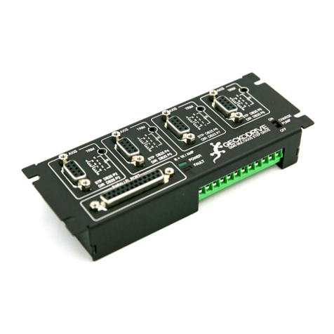
2) MOTOR CABLES: The motors connect to the G540 via male DB9 connectors. The four motor wires connect to
pins 6 and 7 for one motor winding, pins 8 and 9 for the other motor winding. The current set resistor connects to pins
1 and 5. The motor cable should be a 4-conductor cable and it can be shielded or unshielded. If a shielded cable is
used, connect the shield to either pin 2, 3 or 4. Pins 2, 3 and 4 connect to ground inside the G540.
3) CURRENT SET RESISTORS: The current set resistor programs the axis drive current (0 to 3.5A) to match the
rated phase current of the motor being used with the axis. Each axis requires a current set resistor. The resistor can
be from 1/10 W to 1/2 W in size and 1% to 5% tolerance. The current set equals 1,000 Ohms per Amp of motor
current. Example: A 3.3A per phase motor requires a 3.3K resistor, a 1.5A per phase motor requires a 1.5K resistor.
4) POWER SUPPLY: Connect a DC power supply to the MAIN TERMINAL BLOCK, the positive supply wire to Pos
11 and the negative (ground return) wire to Pos 12. The power supply voltage must be between +18VDC and
+50VDC. The power supply voltage determines how fast your motors can go. Supply voltage has no effect on the
motor’s low-speed torque. The power supply can be regulated or unregulated. The power supply current will depend
on the number of motors used and the motors rated phase currents. The power supply current also depends on
motor speed and applied load. A rule of thumb estimate is add up all the motor phase currents and multiply the result
by 0.6 to get the required power supply current.
5) PARALLEL PORT CABLE: Use a parallel port cable to connect the G540 to the PC. The G540 end of the cable
must be a male DB25 connector.
The following items are optional, based on how the G540 is to be used:
6) +5VDC: The PC 5VDC must be supplied to Pos 1 on the MAIN TERMINAL BLOCK if the G540 inputs are going to
be used. 5VDC is available from any USB port, the mouse connector or the keyboard connector.
7) E-STOP SWITCH: Connect a single pole, single throw (SPST) switch to the DISABLE input Pos 6 on the MAIN
TERMINAL BLOCK. The other end of the switch goes to Pos 12 on the terminal block. Closing the switch disables
the G540 and opening the switch enables it. While disabled, the motors freewheel (zero torque) and the OUTPUT
terminals shut off.
8) INPUTS: The G540 has four general purpose inputs called INPUT 0, INPUT 1, INPUT 2 and INPUT 3 on the MAIN
TERMINAL BLOCK. They are at Pos 2, Pos 3, Pos 4 and Pos 5 respectively on the terminal block. These inputs may
be used as limit switches or for any other purpose. SPST switches can be used with these inputs; one end of the
switch goes to the input, the other end of the switch goes to ground (Pos 12).
9) OUTPUTS: The G540 has four general purpose outputs called OUTPUT 0, OUTPUT 1, OUTPUT 2 and OUTPUT
3 on the MAIN TERMINAL BLOCK. They are at Pos 7, Pos 8, Pos 9 and Pos 10 respectively on the terminal block.
These outputs may be used to drive relay coils or for any other purpose. The outputs are rated at 1A and 50VDC
maximum. Connect one end of the load to the output and connect the other end of the load to a positive DC voltage.
This voltage may be the G540 power supply or it may be a separate power supply having a different voltage.
14662 FRANKLIN AVE.
SUITE# E
TUSTIN, CALIFORNIA 92780
1-714-832-8874
GECKODRIVE INC.
6.375"
2.375"
6.000"
1.500"
1.250" 1.000"
1 2 3 4 5 6 7 8 9 10 11 12
5.600"
G540 4-AXIS DRIVE
SPECIFICATIONS, PINOUT AND DIMENSIONS
DB9 MOTOR CONNECTORS: DB25 LPT CONNECTOR: SPECIFICATIONS:
Pin 1 CURRENT SET resistor Pin 1 OUTPUT 1 Four 10-microstep motor drives
Pin 2 GND Pin 2 A-AXIS DIRECTION 0 to 3.5A rated phase current
Pin 3 GND Pin 3 A-AXIS STEP 18VDC to 50VDC supply voltage
Pin 4 GND Pin 4 Z-AXIS DIRECTION Mid-band resonance compensation
Pin 5 CURRENT SET resistor Pin 5 Z-AXIS STEP Auto standby current (70% current)
Pin 6 PHASE B motor wire Pin 6 Y-AXIS DIRECTION Short-circuit protected
Pin 7 PHASE /B motor wire Pin 7 Y-AXIS STEP Opto-isolation on all LPT signal pins
Pin 8 PHASE A motor wire Pin 8 X-AXIS STEP Four 1A at 0 to 50VDC rated outputs
Pin 9 PHASE /A motor wire Pin 9 X-AXIS DIRECTION Four SPST to GND inputs (TTL)
Pin 10 INPUT 0 FAULT indicator LED, signal to PC
Pin 11 INPUT 1 POWER indicator LED
MAIN TERMINAL BLOCK: Pin 12 INPUT 2 I-SET resistor on motor connector
Pin 13 INPUT 3 TRIM adjust for motor smoothness
Pos 1 5VDC from PC Pin 14 OUTPUT 0 Panel mount (5.7” by 2.4” hole dim.)
Pos 2 INPUT 0 (DB25 pin 10) Pin 15 FAULT (input to PC) Anodized aluminum package
Pos 3 INPUT 1 (DB25 pin 11) Pin 16 OUTPUT 3 No heatsink needed below 40C ambient
Pos 4 INPUT 2 (DB25 pin 12) Pin 17 OUTPUT 2 Easy to service removable drives
Pos 5 INPUT 3 (DB25 pin 13) Pin 18 GND Modular PCB design with no internal wires
Pos 6 DISABLE input (E-STOP) Pin 19 GND Conservative ratings, premium components
Pos 7 OUTPUT 0 (DB25 pin 14) Pin 20 GND
Pos 8 OUTPUT 1 (DB25 pin 1) Pin 21 GND
Pos 9 OUTPUT 2 (DB25 pin 17) Pin 22 GND
Pos 10 OUTPUT 3 (DB25 pin 16) Pin 23 GND
Pos 11 SUPPLY +18 to +50VDC Pin 24 GND
Pos 12 POWER SUPPLY GROUND Pin 25 GND
14662 FRANKLIN AVE.
SUITE# E
TUSTIN, CALIFORNIA 92780
1-714-832-8874
GECKODRIVE INC.
1 2 3 4 5 6 7 8 9 10 11 12
C
NC
NO
C
NC
NO
C
NC
NO
C
NC
NO
RELAY
COIL
DC
RELAY
COIL
DC
RELAY
COIL
DC
RELAY
COIL
DC
+VDC
−VDC
+VDC
−VDC
RELAY POWER SUPPLY
MO OR POWER SUPPLY
O PC +5VDC
C
NO
E−S OP
G540 4-AXIS DRIVE
SUGGESTED WIRING DIAGRAM

Other manuals for G540

2

Other Geckodrive DC Drive manuals

Geckodrive G540 User manual

Geckodrive

Geckodrive G540 User manual

Geckodrive G320 User manual

Geckodrive

Geckodrive G320 User manual

Geckodrive G203V Quick start guide

Geckodrive

Geckodrive G203V Quick start guide

Geckodrive G213V User manual

Geckodrive

Geckodrive G213V User manual

Geckodrive G251X User manual

Geckodrive

Geckodrive G251X User manual

Geckodrive GM215 User manual

Geckodrive

Geckodrive GM215 User manual

Geckodrive G210X User manual

Geckodrive

Geckodrive G210X User manual

Geckodrive GR214V User manual

Geckodrive

Geckodrive GR214V User manual

Geckodrive G540 User manual

Geckodrive

Geckodrive G540 User manual

Geckodrive G201X User manual

Geckodrive

Geckodrive G201X User manual

Popular DC Drive manuals by other brands

Danfoss VLT AutomationDrive FC 300 instruction manual

Danfoss

Danfoss VLT AutomationDrive FC 300 instruction manual

Aerotech ANT130L Series Hardware manual

Aerotech

Aerotech ANT130L Series Hardware manual

HNC Electric HV590 Series user manual

HNC Electric

HNC Electric HV590 Series user manual

HAUTAU SA Series Mounting and operating instructions

HAUTAU

HAUTAU SA Series Mounting and operating instructions

Dyer CDC-0252 1-TMS+ Series instructions

Dyer

Dyer CDC-0252 1-TMS+ Series instructions

HP StorageWorks Ultrium 960 User's and service guide

HP

HP StorageWorks Ultrium 960 User's and service guide

Smartrise KEB Series Startup manual

Smartrise

Smartrise KEB Series Startup manual

Rockwell Automation Allen-Bradley PowerFlex 755TS Series installation instructions

Rockwell Automation

Rockwell Automation Allen-Bradley PowerFlex 755TS Series installation instructions

sauter AXM 117SSeries manual

sauter

sauter AXM 117SSeries manual

Esco FA121 EKS Series Mounting and operating instruction

Esco

Esco FA121 EKS Series Mounting and operating instruction

Vacon 100 INDUSTRIAL installation manual

Vacon

Vacon 100 INDUSTRIAL installation manual

Drivecon XS Series Quick setup guide

Drivecon

Drivecon XS Series Quick setup guide

Inovance CP700 Series user guide

Inovance

Inovance CP700 Series user guide

EURONORM JI500 manual

EURONORM

EURONORM JI500 manual

Power Electronics SD750 Series manual

Power Electronics

Power Electronics SD750 Series manual

Siemens SINAMICS G120 CU230P-2 operating instructions

Siemens

Siemens SINAMICS G120 CU230P-2 operating instructions

KEYA DC12/48RT100BL-XW Operation manual

KEYA

KEYA DC12/48RT100BL-XW Operation manual

American Control Electronics PWL400 Series manual

American Control Electronics

American Control Electronics PWL400 Series manual

manuals.online logo
manuals.online logoBrands
  • About & Mission
  • Contact us
  • Privacy Policy
  • Terms and Conditions

Copyright 2025 Manuals.Online. All Rights Reserved.