Topwisdom TL-403 User manual


泰智科技
Shenzhen Topwisdom Technology Co., Ltd
Copyright Statement
Shenzhen Topwisdom Technology Co., Ltd.
All rights reserved.
Shenzhen Topwisdom Technology Co., Ltd. (Topwisdom Technology hereinafter)
reserves the rights of final interpretation and modification for this manual and
declaration. Topwisdom Technology owns the patents, copyright and other intellectual
property rights for its product and software. Without authorization, no one is allowed to
copy, excerpt, reproduce, process, disseminate and use this product and its relative
parts directly or indirectly.
Disclaimer
Topwisdom Technology reserves the right to modify the content described in this
manual without advance notice. Topwisdom Technology is not responsible to any direct,
indirect, or consequential damage or liability caused by improper use of this manual or
the product. Machinery in motion can be dangerous! It is the responsibility of the user
to design effective error handling and safety protection as part of the machinery.
Topwisdom Technology shall not be liable or responsible for any incidental or
consequential damages.
Technical Support
To get our technical support and after-sale service:
Tel: +86-0755-82057902
Fax: +86-0755-82057892
Website: http://www.topwisdom.com.cn

泰智科技
Shenzhen Topwisdom Technology Co., Ltd
I
Content
Part 1 Overview ............................................................................................................... 1
1.1 System Overview ............................................................................................... 1
1.2 Notes and Warning............................................................................................. 2
1.3 Work Environment.............................................................................................. 2
1.4 Power Supply and Grounding............................................................................ 2
1.4.1 Power supply requirements ..................................................................... 2
1.4.2 Grounding requirements .......................................................................... 2
1.5 Accessory List .................................................................................................... 3
Part 2 Wiring Installation Instruction................................................................................ 5
2.1 System Wiring Diagram ..................................................................................... 5
2.2 Installation Dimension ........................................................................................ 6
2.2.1 Panel ........................................................................................................ 6
2.2.2 Mainboard ................................................................................................ 7
2.3 Wiring Instruction................................................................................................ 9
2.3.1 Interface Broad ........................................................................................ 9
2.3.2 Wiring Diagram ........................................................................................ 9
2.4 Interface Instruction.......................................................................................... 13
2.4.1 Power Signal .......................................................................................... 13
2.4.2 U-DISK Port ........................................................................................... 14
2.4.3 PC Connection Port ............................................................................... 14
2.4.4 NETWORK Port ..................................................................................... 14
2.4.5 Output..................................................................................................... 14
2.4.6 Laser Power Interface............................................................................ 16
2.4.7 Input ....................................................................................................... 17
2.4.8 Input Signal Diagram ............................................................................. 19
Part 3 Software Installation............................................................................................ 20

泰智科技
Shenzhen Topwisdom Technology Co., Ltd
II
3.1 Installing CoreDRAW Direct Output................................................................. 20
3.1.1 Manual Install ......................................................................................... 21
3.1.2 Auto install .............................................................................................. 22
3.2 Uninstalling CorelDRAW Direct Output ........................................................... 23
3.3 Installing CAD Direct Output ............................................................................ 23
3.4 Uninstalling CAD Direct Output ....................................................................... 25
3.5 USB Driver Installation ..................................................................................... 26
3.6 USB Port Setting .............................................................................................. 29
3.6.1 View the assigned COM Port by Computer .......................................... 29
3.6.2 Change the Assigned COM port by Computer ..................................... 32
3.7 IP Setting .......................................................................................................... 33
Part 4 Software Operation Guide .................................................................................. 37
4.1 CorelDRAW Direct Output Software Operation .............................................. 37
4.1.1 Layer Parameter Setting........................................................................ 38
4.1.2 Coordinate Setting ................................................................................. 42
4.1.3 Track Setting .......................................................................................... 43
4.1.4 Single Axis Operation ............................................................................ 44
4.1.5 Output Engrave...................................................................................... 45
4.2 The Equipment Management .......................................................................... 49
4.2.1 Toolbar.................................................................................................... 50
4.2.2 Parameter Setting .................................................................................. 50
4.2.3 Embroidery Import ................................................................................. 55
4.2.4 Import bitmap ......................................................................................... 56
4.2.5 Curve Precision...................................................................................... 57
4.3 CAD Direct Output Software Operation........................................................... 57
4.4 CAD Direct Output Software Supplementary Description .............................. 58
4.4.1 The Support of AutoCAD Direct Output Annotation Text ...................... 58
4.4.2 Carving Gradient Sketch Map ............................................................... 60
4.4.3 Coordinate System ................................................................................ 60

泰智科技
Shenzhen Topwisdom Technology Co., Ltd
III
4.4.4 Supplementary Description of Carving ................................................. 61
4.4.5 Supplementary Description of Software and CAD Direct Output......... 62
Part 5 The Operation Panel........................................................................................... 66
5.1 The Panel Operation and Buttons Function Introduction................................ 66
5.1.1 The Panel............................................................................................... 66
5.1.2 Buttons Function Introduction................................................................ 66
5.2 The Main Interface Introduction ....................................................................... 69
5.2.1 Power Interface...................................................................................... 69
5.2.2 Standby Interface ................................................................................... 69
5.2.3 Speed Setting Interface ......................................................................... 71
5.2.4 Power Light Intensity Interface .............................................................. 71
5.2.5 Range Preview Interface ....................................................................... 72
5.2.6 Single Axis Movement Interface............................................................ 73
5.2.7 File Selection Interface .......................................................................... 73
5.2.8 U disk File Interface ............................................................................... 74
5.2.9 The Main Menu Setting.......................................................................... 75
5.3 File Setting........................................................................................................ 76
5.4 The Integrate Settings ...................................................................................... 77
5.4.1 Laser Set ................................................................................................ 77
5.4.2 Equipment Set ....................................................................................... 78
5.4.3 Axis Set .................................................................................................. 80
5.4.4 Back Set ................................................................................................. 83
5.4.5 User Set ................................................................................................. 85
5.5 System Information .......................................................................................... 87
5.5.1 The Password Setting............................................................................ 88
5.6 System Test ...................................................................................................... 89
Part 6 the Frequently Asked Question Help.................................................................. 91
6.1 Power-on Reset Question................................................................................ 91
6.2 The Laser Light Question................................................................................. 92


泰智科技
Shenzhen Topwisdom Technology Co., Ltd
1
Part 1 Overview
1.1 System Overview
Thank you very much for using laser engraving control system of our company!
This system can be used with various types of laser engraving cutting machine, meets
your different requirements for processing.
Use High-Performance 32-Bit CPU with Single-Precision Floating-Point Unit (FPU),
the main frequency is up to 150MH. Setting device parameter out of PC completely.
All coupler completely isolated from outside interference, the system is reliable.
Support USB2.0 port, U disk reading and writing, support U disk system upgrade;
Support network , PC-communication is more convenient, safe, and reliable.
With 64MB storage, work independently form PC, which is useful for the quantities
of engraving and cutting production.
Support 5 axises motion control(X Y Z U V, XY is for laser cutting control, Z is
feeding axis, U is lift axis, V is for the second laser cutting head).
Support double laser head cutting, support leftover cutting. Each laser power is
able to be control independently.
Support feeding, lifting, rotating engraving, metal cutting, scale cutting, automatic
blowing, automatic focusing, foot switch, cover protect, power-off cutting
restoration, system lock, device management.
S-shape acceleration and deceleration and adjustable velocity profile, meet the
demand of smooth cutting and high speed working.
Before using, please read our manual carefully, ensure to operate our system
correctly.
Please keep the manual well, and it’s convenient for your future references.
Because of different configuration, some devices have not some of the
functions listed in the manual, the details subject to appropriate operation
functions.

泰智科技
Shenzhen Topwisdom Technology Co., Ltd
2
1.2 Notes and Warning
Prohibit the non-professionals to maintenance and debug the electrical system, if
not, this will reduce device’s safety performance, and expand failure, even cause
accident and property loss.
Please do not piles up debris on the control box, and in the course of using,
regularly remove the dust of the control box surface and filters, to keep good
ventilation.
When users have to open the cover of the control box, must cut off the power after
5minutes and under the professionals’guidance, only can be allowed to touch the
components in the electrical control box!
Prohibit touching any motion parts or opening the control equipments when the
machine is working, or it maybe bring about the accident and machine can’t work.
Prohibit using the electrical equipment in the damp, dust, corrosive gas, flammable
gas area, or it maybe cause the electrical shock or fire!
1.3 Work Environment
Ventilation, sanitation, and less dust
Storage temperature: 0-50℃
Work temperature: 5-40℃
Work relative humidity: 30%-90%(no condensation)
1.4 Power Supply and Grounding
1.4.1 Power supply requirements
Core power supply: DC 5V, 3A; External power supply: DC 5V, 3A
According to different machine configurations, power consumption is between
0.1-0.2KW
1.4.2 Grounding requirements
In order to prevent electrical equipment due to leakage, over-voltage, insulation etc
causes of the electrical shock or fire, please make the electrical control reliable
grounding.

泰智科技
Shenzhen Topwisdom Technology Co., Ltd
3
Grounding resistance is less than 100 ohms; the length of wire cable is within the
20meters, the cross-sectional area of the wire cable is larger than 1.0 mm2.
1.5 Accessory List
The Laser Engraving Control System-TL-403 contained the accessories as below:
Name
Qty
Introduction
Photo
Operation
Panel
1
For user
operation
Controller
1
The Motion
Control Card
Connection
cable
3
1.Panel
Connection
cable for
connecting
controller and
panel.
2.USB
communication
cable for
connecting
controller and

泰智科技
Shenzhen Topwisdom Technology Co., Ltd
4
PC
3.USB
communication
extended cable
Crossover
Ethernet
Cable
2
1.Crossover
Ethernet Cable
2.Network
communication
extended cable

泰智科技
Shenzhen Topwisdom Technology Co., Ltd
5
Part 2 Wiring Installation Instruction
2.1 System Wiring Diagram
PC
U-DISK
EX5V
EX5V
XGND
IN-5
XGND
OUT6
OUT5
OUT2
OUT1
EX5V
IN-2
IN-3
IN-4
XGND
EX5V
EX5V
PWM4
DIR4
XGND
IN 6
GND
+5V
EX5V
PWM3
DIR3
XGND
IN 1
LASER-2 LASER-1
EX5V
XGND
IN10
IN-7
IN-8
IN-9
EX5V
XGND
IN11
IN12
IN13
EXV+
EXV-
OUT7
OUT8
EX5V
XGND
PWM6
DIR6
EX5V
XGND
PWM5
DIR5
EX5V
XGND
PWM2
DIR2
EX5V
XGND
PWM1
DIR1
X-DRIVERY-DRIVERZ-DRIVERV-DRIVER
DIR
PUL
EX5V
TL-403C
HANDSET
NETWORK
Air Control
Pen Control
5V Relay
5V Relay
EX5V
DIR
PWM
DIR
PWM
- - + +
DIR
PWM
DIR
PWM
- - + +
DIR
PWM
DIR
PWM
- - + +
DIR
PWM
DIR
PWM
- - + +
Axis V Driver
(Laser head2 motor)
Axis Z Driver
(Feeding motor)
Axis Y Driver
(Y motor)
Axis X Driver
(X motor)
U-DRIVER
V Origin Limit
Z Origin Limit
U Origin Limit
Cover Protect
Foot Switch
X Origin Limit
Y Origin Limit
PWM
DIR
PWM
DIR
- - + +
Mechanical
Switch
DC 5V/3A
DC 5V/3A
Water Protect
Water Protect
TH
TL
WP
G
IN
5V
Two way
switch
RP100R
CO2
Laser
power
1
TL
G
IN
CO2
Laser
power
2
Axis U Driver
(Lifting motor)
Control
damper
Control
damper
Auto Manual
Y Up Limit
X Up Limit
5V o0V Optoelectronic
Switch
Fig. 2-1

泰智科技
Shenzhen Topwisdom Technology Co., Ltd
6
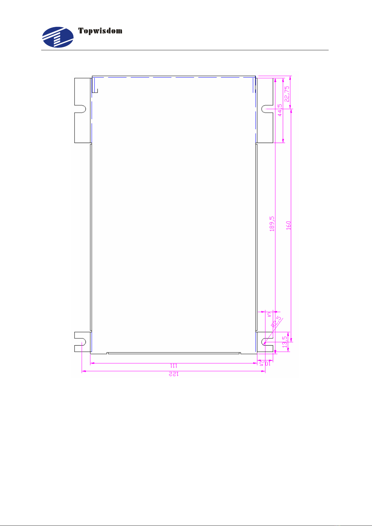
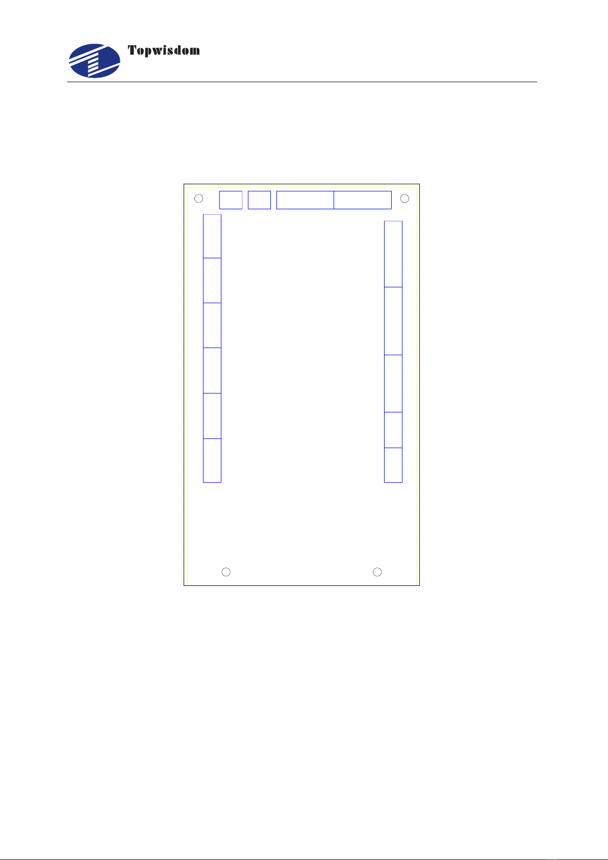
2.2 Installation Dimension
2.2.1 Panel
The installation dimension of operation panel (the unit is MM):
Face:
Fig. 2-2
Bottom:

泰智科技
Shenzhen Topwisdom Technology Co., Ltd
7
Fig. 2-3
2.2.2 Mainboard
The installation dimension of mainboard (the unit is MM):
Fig.2-4
泰智科技
Shenzhen Topwisdom Technology Co., Ltd
8
Fig.2-5
泰智科技
Shenzhen Topwisdom Technology Co., Ltd
9
2.3 Wiring Instruction
2.3.1 Interface Broad
PC
U-DISK
EX5V
EX5V
XGND
IN-5
XGND
OUT6
OUT5
OUT2
OUT1
EX5V
IN-2
IN-3
IN-4
XGND
EX5V
EX5V
PWM4
DIR4
XGND
IN 6
GND
+5V
EX5V
PWM3
DIR3
XGND
IN 1
LASER-2 LASER-1
EX5V
XGND
IN10
IN-7
IN-8
IN-9
EX5V
XGND
IN11
IN12
IN13
EXV+
EXV-
OUT7
OUT8
EX5V
XGND
PWM6
DIR6
EX5V
XGND
PWM5
DIR5
EX5V
XGND
PWM2
DIR2
EX5V
XGND
PWM1
DIR1
X-DRIVERY-DRIVERZ-DRIVERV-DRIVER
DIR
PUL
EX5V
TL-403C
HANDSET
NETWORK
U-DRIVER
Fig. 2-6
2.3.2 Wiring Diagram
2.3.2.1 Motor Wiring
The following is X axis motor wiring, other axis are similar.
1. Step Motor Wiring

泰智科技
Shenzhen Topwisdom Technology Co., Ltd
10
PUL+
PUL-
DIR+
DIR-
ENA+
ENA-
GND
DIR1
PWM1
+5V
GND
U
V
W
Vdc
36V-
To
Motor
36V+
J20 X Driver
Fig. 2-7
2. Panasonic Servo Wiring
PULS1
PULS2
SIGN1
SIGN2
GND
DIR1
PWM1
+5V
COM-
U
V
W
COM+
24V-
To
Motor
24V+
J20 Panasonic servo
3
6
5
4
41
7
Fig. 2-8
2.3.2.2 Laser Power Supply Wiring

泰智科技
Shenzhen Topwisdom Technology Co., Ltd
11
1. CO2 Laser Power Supply Wiring
TTL-H TTL-L WP GND DAC
1 3 4 5 62
Water Potect
EX5V PWM3 DIR3 IN-1 XGND
J2
Laser
Power
Supply
Active low
Fig. 2-9
2.RF Laser Wiring
Power
Water Protect
EX5V PWM3 DIR3 IN-1 XGND
J2
Laser
Power
Supply
GND
Fig. 2-10

泰智科技
Shenzhen Topwisdom Technology Co., Ltd
12
The wiring of laser 2 is similar.
Note:When “RF1 or RF2”is selected, please set the PWM Frequency according
to the data sheet of the laser. Generally, PWM Frequency is 5000Hz. And set the
Laser Max parameter not larger than 95%, especially not to set as 100%,
otherwise it works improperly.
2.3.2.3 Blowing Air Signal Wiring
EXV-
OUT8
OUT7
EXV+
J9 5V/24V Relay
5V+/24V+
Fig. 2-11
2.3.2.4 Pen UP/Down Signal Wiring
EXV-
OUT8
OUT7
EXV+
J9 5V/24V Relay
5V+/24V+
Fig. 2-12
2.3.2.5 Limit Switch Signal Wiring

泰智科技
Shenzhen Topwisdom Technology Co., Ltd
13
XGND
IN-5
IN-4
IN-3
IN-2
EX5V
0V
OUT
5V
J3 Photoelectric limit switch
X Origin limit switch
Fig. 2-13
Other limit switch wirings are similar.
2.4 Interface Instruction
2.4.1 Power Signal
The system is dual 5V power supply
The system internal 5V power interface J24 (switching power interface)
Pin
Definition
1
+5V Internal 5V power source positive (input)
2
GND Internal 5V power source grounding (input)
The system external power interface J23 (switching power interface)
Pin
Definition
1
EX5V External 5V power source positive (output)
2
XGND External 5V power source grounding (output)

泰智科技
Shenzhen Topwisdom Technology Co., Ltd
14
2.4.2 U-DISK Port
Label U-DISK, can directly insert the U disk to read and write.
2.4.3 PC Connection Port
Label PC connection port, can connect PC to read and write with USB.
2.4.4 NETWORK Port
Label NETWORK, can connect PC to read and write by network.
2.4.5 Output
The driver interface
X axis interface J20
Pin
Definition
1
EX5V External 5V power source positive (output) PUL+, DIR+
2
PWM1 Step pulse (output) PUL-
3
DIR1 Direction signal (output) DIR-
4
GND External 5V power source grounding (output)
Y axis interface J18
Pin
Definition
1
EX5V External 5V power source positive (output) PUL+, DIR+
2
PWM2 Step pulse (output) PUL-
3
DIR2 Direction signal (output) DIR-
4
GND External 5V power source grounding (output)
Z axis interface J21
Pin
Definition
Table of contents
Other Topwisdom Control System manuals


