Toray TORAYFIL HFUG-2020AN User manual

Issued in February 2019
TORAY Pressurized PVDF Hollow Fiber
Membrane Module "TORAYFILTM"
Instruction Manual
Model: "HFUG-2020AN" (type AN)
issued by Toray Industries, Inc.
Water Treatment & Environment Division
2-1-1, Nihonbashi-Muromachi, Chuo-ku, Tokyo 103-8666 Japan
Tel: +81-3-3245-4557
Fax: +81-3-3245-4913
URL: www.toraywater.com
BJAIJBAC

Content
I. Introduction .................................................................................................. 1
1. Characteristics of Toray "HFUG series" Membrane Modules....................1
2. About “type AN”.........................................................................................2
3. Applications of Toray "HFUG-2020AN" Membrane Module ......................2
II. For Your Safety ............................................................................................3
1. Safety Instruction for Unpacking and Installation ......................................4
2. Safety Instruction for Filtration Operation..................................................6
3. Safety Instruction for Chemical Cleaning ..................................................8
4. Safety Instruction for Disposal ..................................................................9
III.
Specifications of Toray "HFUG-2020AN" Membrane Module
........................... 10
IV.
Configuration of Toray "HFUG-2020AN" Membrane Module
............................ 13
V. Installation.................................................................................................. 14
VI. Operation ................................................................................................ 17
1. Filtration .................................................................................................. 17
2. Backwash and Air-scrubbing...................................................................19
3. Toray Maintenance Cleaning................................................................... 22
4. Basic Trans-Membrane Pressure Calculation.........................................25
5. Temperature Correction Factor ............................................................... 26
VII. Chemical Cleaning.................................................................................. 27
VIII. Storage of Membrane Module ............................................................. 31
1. Storage of New Membrane Modules....................................................... 31
2. Storage of Membrane Modules after use................................................ 31
3. Replace Preservative Chemical .............................................................. 32

1
I. Introduction
Toray PVDF Hollow Fiber Membrane Module "HFUG series" is a pressurized
hollow fiber UF (Ultra Filtration) membrane module developed with polymer
science and membrane fabrication technologies accumulated over decades of
successful membrane manufacturing at Toray Industries, Inc. The HFUG
series utilizes a fiber with the same physical and chemical properties as the HFU
series, but achieves an increased water production 25% higher than its
predecessor.
The membrane material is Polyvinylidene fluoride (PVDF). The nominal pore
size of the membrane is 0.01 micron, just like the HFU series.
The module, which is permanently potted in its casing, is pressure-driven which
provides equal filtrate quality to submerged modules, while offering greater TMP
range for more flexible plant operation. Maximum operating pressure is 300
kPa (43.5 PSI). Flow direction is outside-in, which is more suitable for higher
turbidity water treatment because of the air-scrubbing effectiveness.
Additionally, outside-in modules are able to remove suspended solids more
effectively at higher recovery rates compared to inside-out fibers.
1. Characteristics of Toray "HFUG series" Membrane Modules
(1) High Filtration Flux
HFUG series provides high filtration flux and stable operation for the filtration
of various raw water sources. The membrane is made with a special
spinning method, which enables high permeability and high fouling
resistance.
(2) Excellent Water Quality
HFUG series provides very good water quality for the filtrate, extremely low
turbidity since the membrane has 0.01 micron nominal pore size. HFUG
series is recommended to be applied to the tertiary treatment of sewage
water and RO pretreatment in seawater desalination.

2
(3) High Mechanical Strength
The membrane of HFUG series has very high mechanical strength because
it is made of PVDF with the special spinning method developed by Toray.
HFUG series provides high integrity and durability under recommended
operating conditions.
(4) High Chemical Durability
The membrane material of HFUG series is PVDF, which allows you to clean
the membrane with high concentrations of chlorine and with high
concentrations of acid resulting in better cleaning and longer sustainable
membrane flux rates.
2. About “type AN”
“Type AN” is a module type which has a slightly modified housing with new
integrated cap, with improved sealing properties. All connecting ports of "Type
AN" modules are identical to "Type N" modules, so "Type AN" modules can
directly replace existing "Type N" modules.
3. Applications of Toray "HFUG-2020AN" Membrane Module
Drinking Water Production
Tertiary Treatment of Sewage Water
RO Pretreatment in Seawater Desalination
Industrial Water Production
Reuse of Industrial Waste Water
3
II. For Your Safety
Please be sure to read and follow the instructions below before using
HFUG-2020AN. This manual should be retained for future reference.
Follow the safety precautions as they are intended to protect operators
and equipment from various risks such as physical harm and/or property
damage. The following table shows a level of potential risk for each
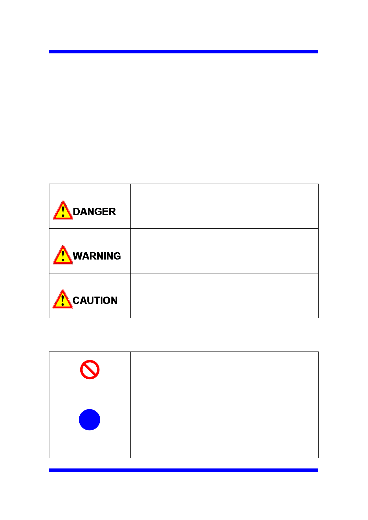
indicated symbol.
This symbol indicates an imminent hazardous situation
which will result in serious injury or death when the
instruction is not observed.
This symbol indicates a potentially hazardous situation
which will result in serious injury or death when the
instruction is not observed.
This symbol indicates a potentially hazardous situation
which might result in injury or property damage when
the instruction is not observed.
The following table explains the information to be noted.
“Prohibited”
This symbol indicates a prohibited action or procedure.
“Instruction”
This symbol indicates an important action or procedure
which has to be taken without fail.
Prohibited
!
!
Instruction

4
1. Safety Instruction for Unpacking and Installation
Be sure to wear safety gear such as rubber gloves and safety glasses
for unpacking. The membrane is packaged in sodium hypochlorite
solution (100 mg/L). If the solution happens to splash onto the skin,
wash the affected part with running water. If the solution happens to
get in the eyes or mouth, wash the affected part with sufficient
amounts of clean running water for more than 15 minutes and see the
doctor immediately.
Be sure to wear safety gear such as a helmet and safety shoes to
avoid injury.
The preservative solution should be drained out before using the
modules. After that, keep clean water in the modules to prevent the
hollow fiber membrane from drying out. Do not allow the modules to
dry even for a few hours.
The membrane modules should not be frozen.
Be careful not to damage or dent the modules during handling.
!
!
Instruction
!
!
Instruction
Prohibited
Prohibited
Prohibited

5
Housing type joints are applied for connecting the modules of
HFUG-2020AN to the piping. Follow the instruction of the Housing
Type Joints Set-up Guide at the connection point. Wrong
connections may damage the modules.
Keep the connection surface free of any dirt or oils.
Be sure to install the modules vertically for effective air scrubbing.
!
!
Instruction
Prohibited
!
!
Instruction
6
2. Safety Instruction for Filtration Operation
Flush all the piping out with clean water and make sure no debris is
remaining in the piping prior to connecting the modules.
Confirm that the preservative chemical in the modules is completely
drained out before starting the filtration operation. The preservative
chemical is harmful to humans.
Flush the modules at low pressure, filling from the bottom, and vent to
remove any air from the modules. Air left in the modules may cause
water hammer and may result in damage to the membrane.
Prior to use, make certain modules are flushed. Filtrate water should
be drained unless it meets the required quality.
Protect modules from direct sunlight and ultraviolet light. Ultraviolet
light can degrade module housing and membranes.
Constantly monitor filtrate water quality such as turbidity and/or the
number of particles during filtration, and stop the operation if abnormal
water quality is detected.
!
!
Instruction
!
!
Instruction
!
!
Instruction
!
!
Instruction
!
!
Instruction
!
!
Instruction

7
Do not exceed the maximum applicable pressure of 300 kPa (43.5
PSI). Higher pressures can damage the modules. Do not exceed
the maximum temperature of 40 degree C (104 degree F). The
higher temperature damages the modules.
Do not freeze the membrane modules.
The operating conditions, including the filtration flux and the periodical
physical cleaning, must be properly set-up otherwise the
trans-membrane pressure may rise too quickly. The operation range
is described in the latter section of this manual.
Do not overfeed air to the modules. Excessive scrubbing air
damages the membranes and/or shortens the membrane life.
The air flow rate should be within the range below for each module
type.
HFUG-2020AN: 4.8 – 9.0 Nm3/h (2.8 – 5.3 scfm)
The maximum required air pressure during the air-scrubbing for inside
of the module will be 40 kPa (6 PSI).
At the integrity tests, such as Pressure Decay Test (PDT) or Diffusive
Air Flow (DAF) Test, keep the air pressure below 130 kPa (18.9 PSI).
Keep the source air pressure lower than 200 kPa (29 PSI), to prevent
excess air inflow. All the air used for air scrubbing and integrity
testing must be dry oil-free air.
Prohibited
!
!
Instruction
!
!
Instruction
!
!
Instruction
Prohibited
8
3. Safety Instruction for Chemical Cleaning
Take special precautions when handling chemicals during chemical
cleaning. Wear the safety gear such as safety glasses and protective
gloves. If chemicals come in direct contact with your skin or your
clothes, treat the contacted part appropriately based on the SDS.
Do not mix sodium hypochlorite with acid. Such mixture generates
toxic chlorine gas.
Stop operation whenever any anomaly occurs with the equipment or
any signs of an anomaly are observed.
In the chemical cleaning, strictly follow the procedure described in the
latter section of this manual. Otherwise you may damage the
modules or negatively affect the membrane performance.
!
!
Instruction
Prohibited
!
!
Instruction
!
!
Instruction

9
4. Safety Instruction for Disposal
When dispose the modules, please apply a service of a qualified waste
disposing company. When the module is to be incinerated, please
apply the appropriate facilities in which hydrogen fluoride (HF) gas can
be neutralized. HF gas is generated with the incineration of
membrane.
!
!
Instruction
10
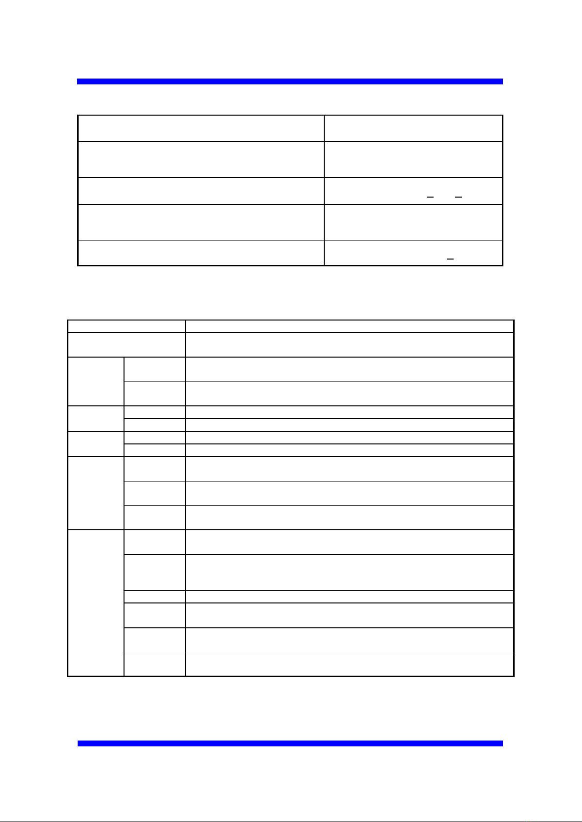
III. Specifications of Toray "HFUG-2020AN" Membrane Module
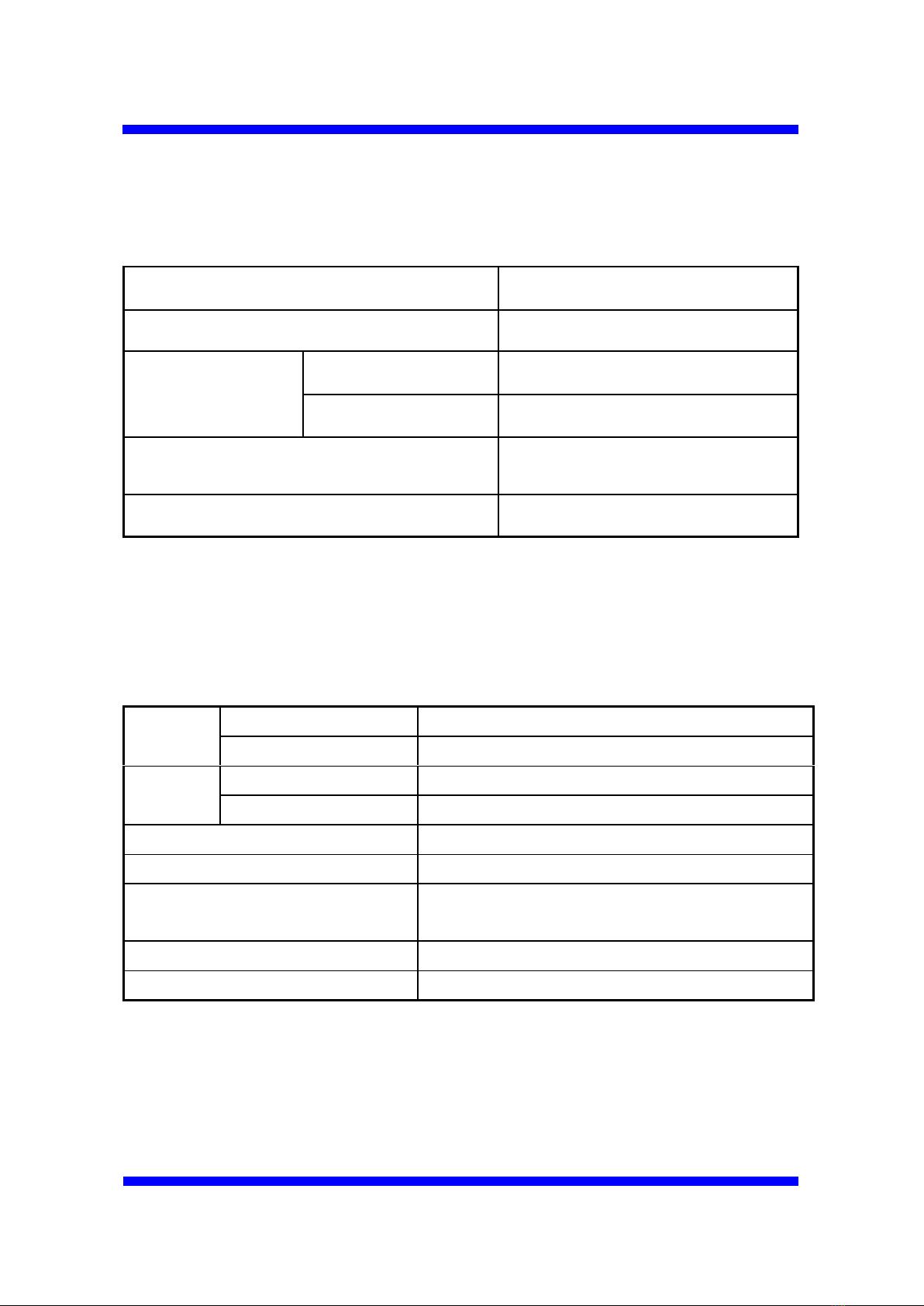
Table 1. Specifications of membrane *1)
Membrane Material
PVDF (Polyvinylidene fluoride)
Nominal Pore Size *2)
0.01 micron
Trans-Membrane
Pressure
Maximum *3)
300 kPa (43.5 PSI)
Normal Operation
Lower than 200 kPa (29.0 PSI)
Storage and Operating
Temperature Range
0 – 40 degree C
(32 – 104 degree F)
Operating pH Range
1 – 10
*1): Please note that the specifications are subject to changes from time to time.
*2): Estimation from removal of model particles.
*3): TMP (Trans-Membrane Pressure) should be below 300 kPa (43.5 PSI) at any time
even during the filtration.
Table 2. Feed water limits *1) , *4)
Turbidity
Intermittent Peak *5)
200 NTU
Continuous Maximum
50 NTU
TSS
Intermittent Peak *5)
200 mg/L
Continuous Maximum
50 mg/L
Ozone
Not detected
Pretreatment Filter Mesh Size
Smaller than 200 micron meter
Temperature Range
0 – 40 degree C
(32 – 104 degree F)
pH Range
1 – 10
Maximum Feed Pressure
300 kPa (43.5 PSI)
*1): Please note that the specifications are subject to changes from time to time.
*4): In case of design, please contact us.
*5): The duration time should be less than 48 hours and the occurrence frequency
should not exceed more than once a month.
11
Table 3. Cleaning limits *1)
Cleaning pH Range
0 – 12
Cleaning Temperature Range
0 – 40 degree C
(32 – 104 degree F)
Maximum Concentration of NaClO as Cl2
3,000 mg/L (10 < pH < 12)
Maximum NaClO Exposure
(lifetime contact time) as Cl2
1,000,000 mg/L hours
Maximum Acid Contact Time
1,000 hours (pH > 0)
*1): Please note that the specifications are subject to changes from time to time.
Table 4. Specifications of modules *1)
Module Type
HFUG-2020AN
Membrane Surface Area
(Outer Surface)
90 m2
(969 ft2)
Dimensions
Diameter
216 mm
(8.50 inches)
Length
2,160 mm
(7.087 ft.)
Weight
Full of Water
92 kg (203 lbs)
Drained
49 kg (108 lbs)
Materials
Housing
PVC and/or equivalent
Potting
Epoxy and/or equivalent
Connections
Top
Housing type joint
80A
Bottom
Housing type joint
80A
Side
Housing type joint
65A
Operating
Conditions
Max. Feed
Water Flow
15 m3/h (66 gpm)
Max.
Backwash
Flow
16.8 m3/h (74 gpm)
Max. Air Flow
9.0 Nm3/h (5.3 scfm)
Filtration
Method
Outside to inside, dead end
Max. Inlet
Pressure
300 kPa (43.5 psi)
Maximum
Temperature
40 degree C (104 degree F)
*1): Please note that the specifications are subject to changes from time to time.

12
Handle and operate the modules within the ranges
and the limits indicated in Table 1 to 4. Operation
out of these ranges or limits may damage the
modules, and affect filtration performance.
13
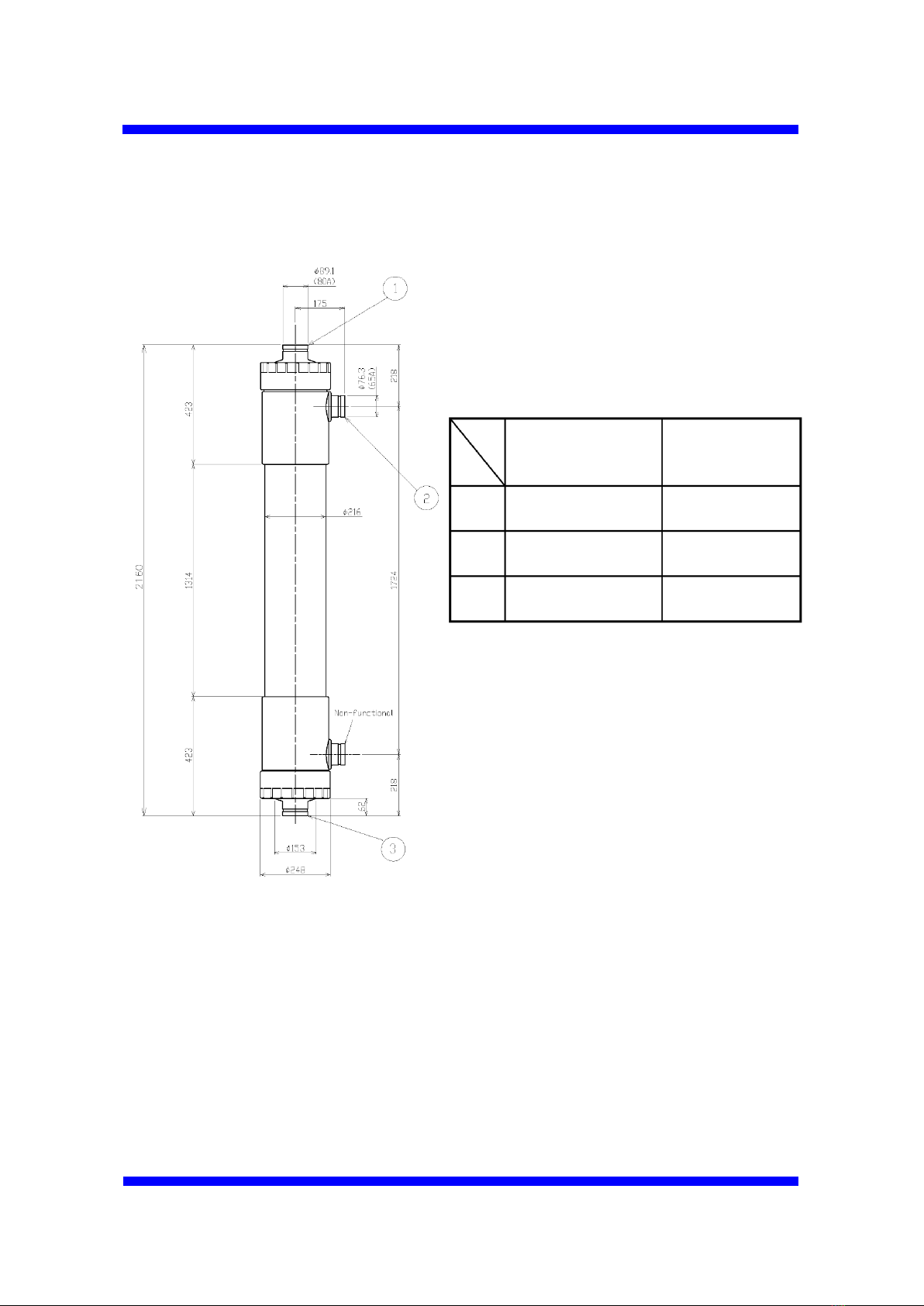
IV. Configuration of Toray "HFUG-2020AN" Membrane Module
(1): Filtrate Outlet / Inlet of Backwash
Water
(2): Air Outlet / Backwash Water Outlet
(3): Feed Water Inlet / Air Inlet / Drain
Outlet
Connections
Pipe fitting outer
diameter
mm (in)
Connectors
(1)
89.1 (3 1/2”)
Housing type
joint 80A
(2)
76.3 (3”)
Housing type
joint 65A
(3)
89.1 (3 1/2”)
Housing type
joint 80A
Fig. 1 Type: HFUG-2020AN
14
V. Installation
The standard method to install the membrane modules is described below.
1. Unpack the membrane module from wooden box or corrugated box.
2. Remove plugging plate from each nozzle of the module.
3. Drain out the preservative solution from the module.
Wear rubber gloves and safety glasses when you
drain the preservative chemical. Note that the
preserving chemical is sodium hypochlorite
solution (100 mg/L of chlorine). If this solution
splashes onto your skin, wash the affected part
with running water. If the solution gets in your eyes
or mouth, wash the affected part with enough
amounts of running water for over 15 minutes and
see the doctor immediately.
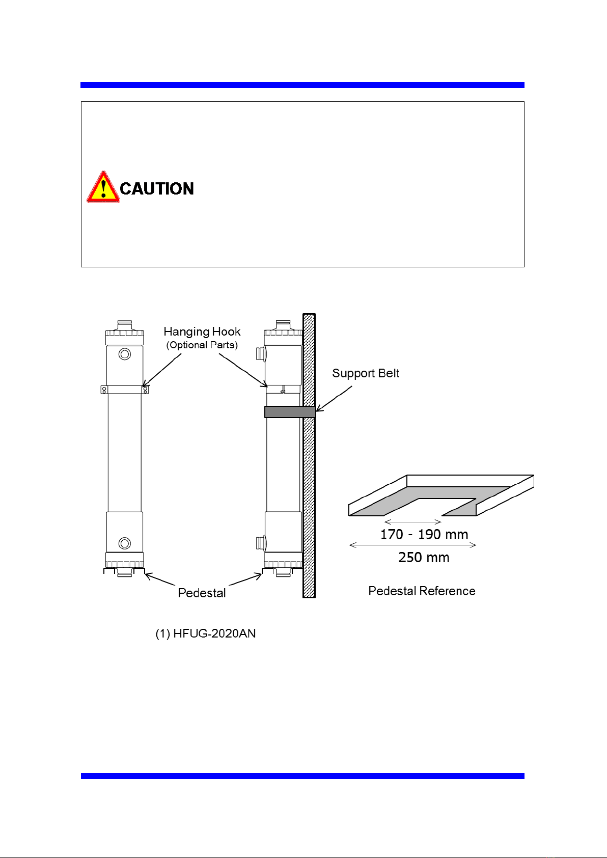
4. Put the module vertically on the pedestal in the module rack. Fix the
module upright with the hanging hook and/or the supporting belt (see Fig. 2).
Do not drop the module.
Use equipment such as chain blocks, a crane or a
forklift truck when you handle the module. The
HFUG-2020AN module is too heavy to handle by
hand.
15
Be careful not to install the module upside down.
Confirm the module is installed in the right
direction.
Do not overtighten the module with the hanging
hook and/or the supporting belt, or you may
damage the module.
Do not allow the hollow fiber membranes to dry
even for a few hours, especially in summer.
Do not freeze the module.
Fig. 2 Installation of the membrane module
16
5. Connect the piping to each connection point of the module with Housing type
joints (HFUG-2020AN) (see Fig. 3). The maximum fastening power of the
Housing type joints should not exceed 40 Nm. When you tighten or loosen
the Housing type joints, make certain to maintain sufficient space prior to the
work and be careful not to be wounded by swinging out or clipping your
fingers.
Keep the connection surface free of any dirt or oils.
Follow the instruction of the Housing Type Joints
Set-up Guide when using Housing Type Joints. A
wrong use may cause the damage to the module.
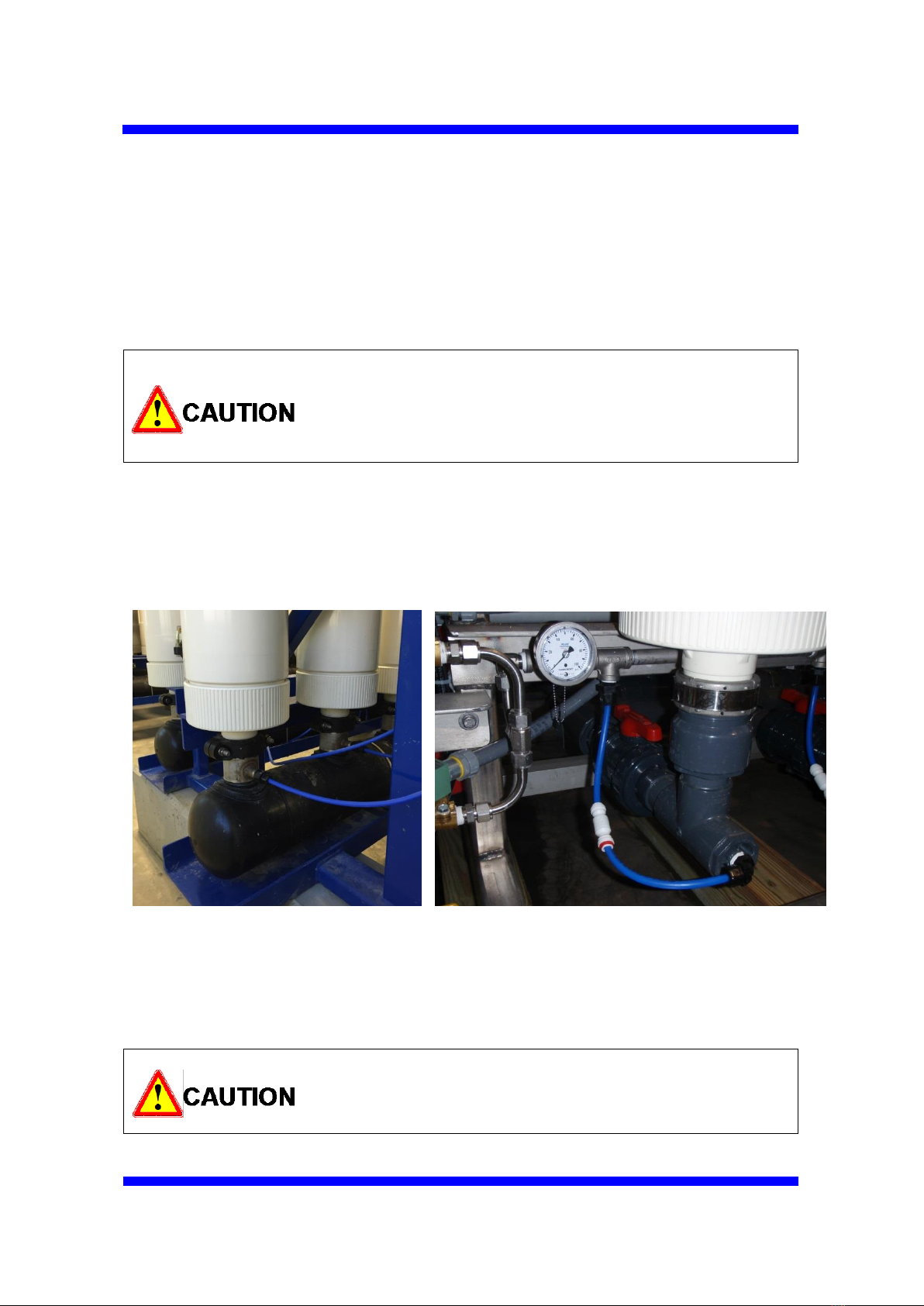
6. Air inject should be located just beneath the bottom nozzle of the module to
inlet air completely to the module. Please refer to the below photos. Also, a
check valve is necessary to the air piping to avoid water reverse flow.
Good location for air inject Poor location for air inject
Good location for check valve
7. Make sure that the module is installed vertically.
If the module is not installed vertically, the effect of
the air scrubbing would be reduced and an
effective filtration will be impaired.
17
VI. Operation
1. Filtration
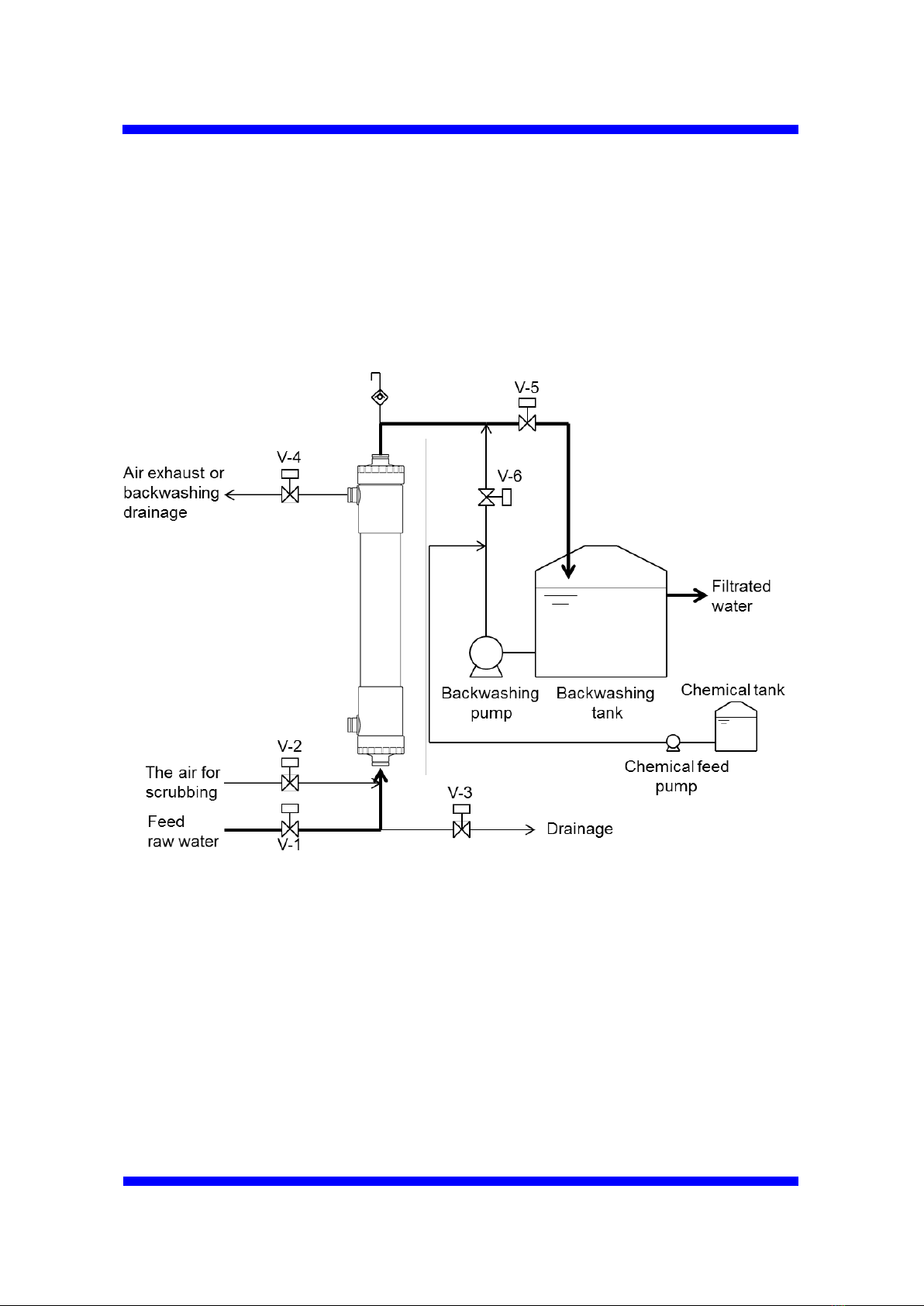
(1) Check that all piping is connected appropriately and flushed out prior to the
operation. Fig. 3 shows a typical example of piping.
(2) Make sure the feed water valve (V-1), the drainage valve (V-3) and the valve
for the scrubbing air (V-2) are “closed”.
(3) Make sure the filtrate water line is open. Open the air exhaust valve (V-4).
(4) Gradually open the feed water valve (V-1) and charge the feed water to the
module to purge any air out.
Fig. 3 Typical example of piping
18
Do not open the feed water valve (V-1) quickly, or
water-hammer may occur and the module could be
damaged.
(5) Confirm that the air is out of the module, and then close the air exhaust valve
(V-4).
(6) Set appropriate volume of filtrate water flow.
Do not exceed 300 kPa (43.5 PSI) to avoid
damage to the module.
Operating conditions including the filtration flux
and the physical cleaning should be properly set
up, observing the rise of trans-membrane pressure
(Details are described in the next session.).
Please contact us if you need technical support.
(7) When stopping operation, gradually close the feed water valve (V-1).
Table of contents
Other Toray Control Unit manuals


Popular Control Unit manuals by other brands


Honeywell
Honeywell 7800 SERIES manual

Ewert Energy Systems
Ewert Energy Systems Orion Jr. 2 BMS Wiring & installation manual

Middle Atlantic
Middle Atlantic MPR-A Series instruction sheet

Omron
Omron F3SP-B1P user manual

STIEBEL ELTRON
STIEBEL ELTRON HUV 1 Operating and installation

Watts
Watts 2300 Series installation instructions


