IDEC HR1S-ATE User manual

S1A11145.00
1 / 18
2/2010
非常停止回路モニタ用安全リレーモジュール
(EN ISO/ISO 13850 / EN/IEC 60204-1 適合)
外形寸法
端子配列
正面図
注記
遅延時間(K3、K4)、12 段階で調節可能
HR1SATE ・ : 0 ~ 30 秒
114 mm
(4.48 in)
99 mm
(3.89 in)
45 mm
(1.77 in)
35 mm
(1.38 in)
HR1S-ATE5110
99 mm
(3.89 in)
114 mm
(4.48 in)
45 mm
(1.77 in)
35 mm
(1.38 in)
HR1S-ATE5110P
A1
58
S33
68
Y1
78
Y2
Y3
2
Y5
Y4 14
B1 23
13 Y+
24
Y1Y2
5767 77 Y+
A123
24
78
TYPE
HR1S - ATE
SAFETY RELAY MODULE
Y88 Y89Y90Y91
S11 S21
S12 S22
13
B1
5868
S33
A2
14
Y3
Y4
Y5
S12 S22
S11 S21
Y88 Y89Y90 Y91
57 67 77
A1/A2
Fuse
Input
A
S12
Input
B
S22
Stop 1
6878Y88Y89Y90
58Y91
67
77
57Y+
24
23
14
13
20
2
4
6810
15
25
30
0
0,5
1
Time [s]
A1/A2
Fuse
I
nput A
S12
I
nput B
S22
Stop 1
6878Y88Y89Y90
58Y91
67
77
57Y+
24
23
14
13
20
2
4
6810
15
25
30
0
0,5
1
Time [s]
HR1S-ATE5110P
HR1S-ATE5110
HR1S-ATE5110P
危険
危険電圧に関する遵守事項
関係する専門機関や事業者団体が公布する電気関連のすべての安全規制を遵守
してください。本来の用途以外でモジュールを使用された場合、安全機能が失
われる可能性があります。
筐体を開いたり、その他の不正な操作を行った場合、保証は無効になります。
注意
用途外使用
モジュールが不適切または誤って使用されている場合は、使用を中止してくだ
さい。この場合、保証は無効となります。
落下や規格外の電圧、電流、温度、湿度など、強い機械的ストレスを与えた状
態で使用しないでください。
初回起動時は、規定に従って事前に機械や設備の安全機能をすべて確認し、安
全装置についても、規定の周期に沿ってテストを行ってください。
注意
取付け時のリスク
取付け、組立て、分解時は、事前に以下の予防措置を行ってください。
1. 作業を開始する前に、モジュールやシステムの電源電圧を遮断する。
2. モジュールやシステムのロックアウトやタグ付けを行って、不慮の起動を
防止する。
3. 電圧がかかっていないことを確認する。
4. 配線図に記載のN(-)を接地する。
5. 保護装置や防壁を使用して近接した動作中の部品から保護する。
6. モジュールは、保護等級が IP54 以上のキャビネット内に設置する。
注意
接点保護の制限
・ 保護タイプは EN/IEC 60529 に従ってください。
・ 筐体 / 端子部 : IP 40 / IP 20
・ フィンガープロテクションは EN 50274 に従ってください。
57
Y88 67
Y89 77
Y90 Y+
Y91
S33
58 Y1
68 Y2
78
B1
A1 S11
S12 S21
S22 13
23
A2
Y3 Y4 Y5 24
14
A1
B1
S12
S11
S22
S21
23
13
Y3
A2
Y4 Y5
24
14
Y88
57
Y89
67
Y90
77
Y91
Y+
58
S33
68
Y1
78
Y2
!
!
!
!
!
HR1S-ATE SAFETY RELAY MODULE OPERATING INSTRUCTIONS
B-1153(0)
HR1S-ATE5110 HR1S-ATE5110P
A1/A2 - Fuse LED 緑
Input A - S12 LED 緑
Input B - S22 LED 緑
Stop 1 LED 緑
上記の指示を厳守できない場合、死亡事故や重傷を伴う事故につながる
恐れがあります。
上記の指示を厳守できない場合、怪我を伴う事故やモジュールの損傷に
つながる恐れがあります。
上記の指示を厳守できない場合、怪我を伴う事故やモジュールの損傷に
つながる恐れがあります。
上記の指示を厳守できない場合、怪我を伴う事故やモジュールの損傷に
つながる恐れがあります。
TYPE
HR1S - ATE
SAFETY RELAY MODULE
本モジュールの取付け、起動、構成の変更、部品の追加は、必ず訓練を受けた
専門の電気技術者が行ってください。
作業を開始する前に、モジュールやシステムの電源をすべて切断してください。
取付けたモジュールまたはシステムでエラーが発生した場合は、DC アイソ
レーションが行われずに、モジュールの制御回路に線間電圧がかかっている可
能性があります。

2 / 18
非常停止回路モニタ用安全リレーモジュール
・ 停止カテゴリ 0(EN/IEC 60204-1):
- PL e / カテゴリ 4
HR1S-ATE モジュールには電子ヒューズが内蔵されています。これは、モジュール
を外部短絡(入力回路の+極と-極の短絡など)による損傷から保護するためのもの
です。モジュールは、エラーを取り除いて数秒後に再び動作可能な状態になります。
適切な使用
注記
注記
安全関連機関の指示を遵守してください。
注記
モジュール内にはユーザ側で保守する部品はありません。停止カテゴリ 0 で使用す
るためには、端子 13-14 間と端子 23-24 間の接点出力のみを使用してください。
また、停止カテゴリ 1 で使用するためには、端子 57-58 間、端子 67-68 間、端
子 77-78 間の接点出力のみを使用してください。
注意
残留リスク(EN ISO/ISO 12100-1)
以下の配線図は、実際の使用条件下で慎重にテストしたものです。適用規格に
準拠した安全装置と接続することにより、モジュールは安全機能を発揮できま
す。しかし、次のような場合には、残留リスクを考慮してください。
a) 推奨された回路構成を変更する必要があり、追加・変更された部品が制御
回路に正しく組込まれていない場合。
b) 機械操作の適用規格に従わなかった場合。または、機械の調整・保守が適
切でない場合。規定された機械保守スケジュールを厳守してください。
c) 使用するリレーの接点が強制ガイド式でない場合。
警告
保護の履行に関する遵守事項
・ 配線例に従い安全リレーモジュールを配線すること。
・ 適合規格に従い配線すること。
・ 安全出力には強制ガイド式接点を持つ機器を接続すること。
・ 外部フューズは、配線例に従い、適切なサイズのものを接続すること。
・ 機械を保守・調整するときは規定された保守スケジュールを厳守すること。
!
!
!
!
- MTTFd = 134.8 年
- PFHd = 6.81 x 10 -9
- SILCL 3
・ 停止カテゴリ 1(EN/IEC 60204-1):
- PL d / カテゴリ 3
- MTTFd = 54.5 年
!
!
上記の指示を厳守できない場合、怪我を伴う事故やモジュールの損傷に
つながる恐れがあります。
上記の指示を厳守できない場合、死亡事故や重症を伴う事故、またはモジ
ューやモジュールの損傷につながる恐れがあります。
- DC = 99%以上
- PFHd = 1.96 x 10 -8
- SILCL 2
・ 手動起動または自動起動
・ 3 個の安全出力、1 個の補助出力
・ フィードバックループで外部コンタクタをモニタリング
用途
安全システムは多数の部品から成り立つものであり、一つの安全部品のみでシステ
ムの安全性を保証するものではありません。最初にどのような安全システムを構築
するかを考え、適用安全規格に従って構成部品の取付けや配線を行ってください。
免責事項
機能
- DC = 98.42%
電気機器の取付け、操作、修理、保守は、必ず有資格者が行ってください。IDEC 社は、
本モジュールの使用によって生じたいかなる結果についても、その責任を負わない
ものとします。
HR1S-ATE モジュールは、単独または複数の回路を遮断することができ、
EN/IEC60204-1 に準拠した非常停止回路や安全回路に組込んで使用するよう
に設計されています。原則として、本モジュールは、非常停止装置と安全回路に関し
て、ヨーロッパの標準規格である EN ISO/ISO 13850 と EN/IEC 60204-1
にそれぞれ準拠しています。これらの規格は、特に、一つの非常停止命令で複数の回
路を遮断する必要がある用途(間接的非常停止)に対応しています。また、本モ
ジュールは、インターロックガードにおいてリミットスイッチの電気的モニタリ
ングの安全基準にも準拠しています(EN 1088)。
本モジュールには、停止カテゴリ 0(EN ISO/ISO 13850 / EN/IEC 60204-1)
の直接開路安全出力(2 個)に加え、停止カテゴリ 1 の遅延開路安全出力(3 個)が装
備されています。これらの出力により、駆動装置の減速動作を制御し、駆動装置を確実
に停止することができます。これには、スピード可変駆動装置によるモータのブレーキ
ングなどがあります。あらかじめ設定した遅延時間後に遅延出力回路を開くことで電
力を安全に遮断できます。端子 57-58 間、端子 67-68 間、端子 77-78 間の 3
個の出力回路の遅延時間は、フロントカバー上の 12 段階のセレクタスイッチによ
り 0 ~ 30 秒の範囲で調節できます。遅延時間の設定にはドライバを使用してくだ
さい。
本モジュールでは最大 2 個の入力チャネルを使用できます。エラー検出性能の向上に
より安全性が向上しますので、入力チャネルは 2 個使用することをお勧めします。これ
により、接続ケーブルがモニタリングに組込まれ、単一故障はすべて検出されます。
・ EN ISO/ISO 13849-1 適合のパフォーマンスレベルや安全カテゴリは、外部配
線、用途、使用する制御局とその機械上での物理的な配置により変化します。
・ EN ISO/ISO 14121-1 に従ってリスク評価を行ってください。
・ 本書に基づき、適合規格に従ってシステムと機械を総検証してください。
・モジュールには電気機械リレーが内蔵されています。このため、表示されるパフォー
マンスレベル(PL)値や MTTFd 値は、使用時の負荷や動作回数に応じて変化します。
上述の PL 値および MTTFd 値は、定格負荷で年あたりのスイッチング回数が最大
6,336 回、または低負荷でスイッチング回数が最大 316,800 回に相応します。
・ 電流負荷がわかっている場合は、電気的寿命のグラフ(6/18 ページを参照)を使用
して最大スイッチング回数を算出してください。この方法で算出したスイッチン
グ回数でのみ、指定したパフォーマンスレベルを確保することができます。
モジュールは、寿命を超えて使用されることのないよう、算出した最大値に到達し
たら交換してください。
・ 仕様に記載のないモジュール操作を行った場合、誤動作やモジュールの破損が生
じる可能性があります。
・ 入力 A1 は制御入力として機能します。これにより、短絡を遮断したり、動作電圧
UB より低くして放出経路に切り替えることができます。
・ プラス接点付の拡張機器または外部コンタクタを使用して、安全出力を 2 重化
できます。
・ リセットスイッチを使用する場合は、あらかじめ非常停止回路を閉じておいてく
ださい。
・ リード接点付磁気スイッチまたは半導体出力付センサを使用している場合は、ス
イッチがオンのときの最大電流に注意が必要です(「技術仕様」を参照)。
・ 取付けに関する注記をご覧ください。
・ EN/IEC 60204-1・EN ISO/ISO 13850 適合の非常停止モニタ用安全リレ
ーモジュール
注意
!
モジュールの損傷防止に関する遵守事項
・ 外部ヒューズは、「HR1S-ATE 安全リレーモジュール配線図」に従って接
続してください。
・ 出力保護については本書の「技術仕様」を参照してください。
上記の指示を厳守できない場合、怪我を伴う事故やモジュールの損傷に
つながる恐れがあります。
警告
回路構成と保守に関する遵守事項
・ 推奨された回路構成を変更した場合や部品を追加・変更した場合は、これら
が制御回路に正しく組込まれているのを確認すること。
・ リレーは強制ガイド式接点を備えていること。
・ 機械操作は適用規格に従うこと。また、適切に機械を調整し、規定された機
械保守スケジュールを厳守すること。
・ 以下の配線図に従い安全リレーモジュールを配線すること。
!
上記の指示を厳守できない場合、死亡事故や重症を伴う事故、またはモジ
ューやモジュールの損傷につながる恐れがあります。
製品ラベルに記載されている供給電圧を端子 A1/A2 に印加してください。制御装
置は以下のように接続してください。
1 チャネル接続の場合:
制御装置(非常停止)の接点を端子 S11-S12 に接続してください。端子 S21-
S22 間と端子 B1-S12 間は短絡してください。
2 チャネル接続の場合:
制御装置(非常停止)の接点を端子 S11-S12 と端子 S21-S22 に接続してくだ
さい。端子 B1-S11 間は短絡してください。
2 チャネル接続の場合、2 個の入力回路の極性が異なるため、+極と-極の間で短
絡を検出できます。しかし、極性が異なることが問題となる場合、制御装置を端子
S11-S12 と端子 S11-B1 に接続し、端子 S21-S22 間を短絡してください。こ
の場合、チャネル間の短絡は検出されません(挟まれたケーブルは検出されません)。
安全機能出力によって切り替わる外部リレーやコンタクタの NC 接点と同様に、起
動スイッチも端子 S33-Y2 の間のフィードバックループ内に設置してください。
これにより、これらの安全関連のリレーの電力が停止命令で遮断された場合にのみ
モジュールが起動するようになります。なお、フィードバックループは新しい起動命
令ごとに閉じる必要があります。配線の便宜上必要であれば、端子 Y1 を使用してく
ださい。端子 Y1 は内部接続されていません。
起動スイッチの機能はジャンパの位置で決まります。端子 Y3-Y5 を短絡した場
合、起動スイッチはモニタリングに組込まれます。この場合、起動信号の立ち下がり
時(起動スイッチ解除時)にモジュールの出力はオンになります。端子 Y3-Y4 を短
絡した場合、起動スイッチを押すとすぐにモジュールの出力はオンになります。た
だし、入力デバイス回路は閉じている必要があります。端子 Y3-Y5 間または端子
Y3-Y4 間のジャンパ線は短くし、モジュールに直接接続してください。
なお、ジャンパの使用は一箇所だけ(端子 Y3-Y5 または端子 Y3-Y4 間のいずれ
か)にしてください。また、これらの端子には他の接続は行わないでください。
「HR1S-ATE 安全リレーモジュール配線図」に従って外部ヒューズを必ず接続し
てください。出力保護を最大にするには「技術仕様」を参照してください。
本モジュールは、各機械の安全装置で使用される非常停止スイッチやポジション
スイッチなどのセンサをモニタリングし、作業者や構成部品、機械類を保護します。

3 / 18
HR1S-ATE 安全リレーモジュール配線図
S2
S1
S11S21A1 13 57 67
A2 S33 Y1 Y2 Y3 Y4 Y5 14 24 6858
S22B1 S12 23
F1
K2 K4K1
K1
K3
L1 (+)
N (-)
K3
K4
K1
K2
Timer 1
Time (s)
Timer 2
ESC
K1
K2
K3
K4
HR1S-ATE
LOGIC
77
78 Y88 Y89 Y90 Y91
Y+
(A1/A2)
(S12)
(S22)
(Stop1)
(最大4A)
停 止
カテゴリ0
停 止
カテゴリ1
起動スイッチのモニタリングあり、
立ち下がり時に起動
(工場出荷状態・推奨)
起動スイッチのモニタリングなし、
立ち上がり時に起動
出力はヒューズを通すこと(最大
ヒューズサイズについては技術仕
様を参照)
PLC へ
S1 = 2 個の NC 接点を備えた非常停止スイッチ (推奨)
S2 = 起動スイッチ
ESC = 外部起動条件
Y1(S33) - Y2 = フィードバックループ
S3
S11S21
A1 13 77
S22
B1
S12
23 57 67
S2
S1
HR1S-ATE
複数の非常停止スイッチの接続
S11S21
A1 13 77
S22
B1
S12
23 57 67
S1
HR1S-ATE
1 個の NC 接点を備えた非常停止スイッチ
(全ての故障を検出することはできません。:
非常停止スイッチ配線部分の短絡故障は検出できません。)
A2
S33
Y1 Y2 Y3 Y4 Y5
HR1S-ATE
S2
起動スイッチのモニタリングなし、立ち上がり時に起動
S2 周辺の点線は自動起動の配線を示す。
S2
A2
S33
Y1 Y2 Y3 Y4 Y5
HR1S-ATE
起動スイッチのモニタリングあり、立ち下がり時に起動
(工場出荷状態・推奨)
S11S21A1 7731S22B1 S12 23 57 67
S1
HR1S-ATE
2 個の NC 接点を備えた非常停止スイッチ
( 端子 B1-S12 間の短絡は検出されません。)
!
HR1S-ATE SAFETY RELAY MODULE OPERATING INSTRUCTIONS
K2
+24V
T

4 / 18
HR1S-ATE 安全リレーモジュール配線図(スピード可変駆動装置に接続した場合)
システム診断用の LED(フロントカバー上に配置)
S2
S1
S11S21
A1 13 57 67
A2
S33
Y1 Y2 Y3 Y4 Y5 14 24 786858
S22
B1
S12
23 77
F3
KM1
KM2
KM2KM1
Q1
KM2
U
W
KM1
W
V
M1
3
F1
+ 24 V
L3L2
U/T1 V/T2
W/T3
L1
R1
T1
FW RV
HR1S-ATE
0…30 s
F2
PLC
(1)
(2)
(A1/A2)
Y88 Y89 Y90 Y91
Y+
(S12)
(S22)
(Stop1)
(1) = 起動スイッチのモニタリングあり、立ち下がり時に起動
(工場出荷状態・推奨)
(2) = 最大ヒューズサイズについては技術仕様を参照
周波数変換器
PLC へ
1 A1/A2 - Fuse
2 Input A - S12
3 Input B - S22
4 Stop 1
フロントカバー上の LED の配置
LED1:(A1/A2- Fuse)
端子 A1/A2 の電力供給状態を表す。
LED2:(Input A - S12)
端子 S11-S12 間の第 1 入力回路の状態を表す。端子 S12 がプラス電位であれば LED2 が点灯する。
LED3:(Input B - S22)
端子 S21-S22 間の第 2 入力回路の状態を表す。端子 S22 がマイナス電位であれば LED3 が点灯する。
LED4:(Stop 1)
3 つの遅延出力回路の状態を表す。出力端子 57-58 間、67-68 間、77-78 間が閉じていれば LED4 が点灯する。
HR1S-ATE SAFETY RELAY MODULE OPERATING INSTRUCTIONS
+24V
PE

5 / 18
HR1S-ATE 動作チャート図
起動スイッチのモニタリングあり、端子
Y3-Y5 間のジャンパあり
(工場出荷状態・推奨)
起動スイッチのモニタリングなし、端子
Y3-Y4 間のジャンパあり
動作表示
オン オフ
ンオ源電 非常停止スイッチ解除起動
非常停止(NC1)
非常停止(NC2)
起動スイッチ
tmax.= 75 ms
起動スイッチ
Tv = 0 ~ 30 秒
調整可
起動スイッチ
出力 77-78(NO)
出力 23-24(NO)
トランジスタ出力 Y88(A1/A2)
出力 67-68(NO)
出力 57-58(NO)
出力 13-14(NO)
外部起動条件
トランジスタ出力 Y90(S22)
トランジスタ出力 Y91(Stop 1)
トランジスタ出力 Y89(S12)
起動スイッチなし、端子 Y3-Y4 間と端子
S33-Y1 間のジャンパあり
起動スイッチあり
起動スイッチなし
出力
トランジスタ出力 Y90(S22)
トランジスタ出力 Y89(S12)
非常停止(NC2 または NC1)
非常停止(NC1 または NC2)
HR1S-ATE SAFETY RELAY MODULE OPERATING INSTRUCTIONS
非常停止スイッチ押下

6 / 18
出力接点の電気的寿命(EN/IEC 60947-5-1/ 付録 C.3)
1
10
100
10 10 10 10
7654
DC 1: 24 V
DC 13: 24 V
(< 0,1 Hz)
AC 15:
230 V
AC 1:
230 V
AC/DC 24 V モデル
動作回数
公称動作電流 x 0.1 A
技術仕様
- 端子と接続
HR1S-ATE5110
単線接続
ケーブル終端なし
mm 5.2~41.0:線単 2
AWG 26 ~ 14
mm 5.2~41.0 :線りよ 2
ストリップ長さ: 7 mm(0.28 in.)
ケーブル終端つきフレキシブル
(ビニール被覆なし): 0.25 ~ 2.5 mm 2(24 ~ 14 AWG1))
(ビニール被覆あり): 0.25 ~ 1.5 mm 2(24 ~ 16 AWG1))
最小締付けトルク : 0.5 Nm(4.4 lb-in)
複線接続(最大 2 本)
ケーブル終端なし
mm 57.0~41.0:線単 2(26 ~ 20 AWG1))
mm 57.0~41.0:線りよ 2(26 ~ 20 AWG1))
ストリップ長さ: 7 mm(0.28 in.)
ケーブル終端つきフレキシブル
(ビニール被覆なし): 0.25 ~ 1 mm 2(24 ~ 18 AWG1))
ツインケーブル終端つきフレキシブル
(ビニール被覆あり): 0.5 ~ 1.5 mm 2(22 ~ 14 AWG1))
最小締付けトルク : 0.5 Nm(4.4 lb-in)
HR1S-ATE5110P
単線接続
ケーブル終端なし
mm 5.2~2.0:線単 2
mm 5.2~2.0:線りよ 2
ストリップ長さ: 7 mm(0.28 in.)
ケーブル終端つきフレキシブル
(ビニール被覆なし): 0.25 ~ 2.5 mm 2(22 ~ 14 AWG1))
(ビニール被覆あり): 0.25 ~ 1.5 mm 2(22 ~ 16 AWG1))
最小締付けトルク : 0.5 Nm(4.4 lb-in)
複線接続(最大 2 本)
ケーブル終端なし
mm 1~2.0:線単 2(24 ~ 18 AWG1))
mm 5.1~2.0:線りよ 2(24 ~ 16 AWG1))
ストリップ長さ: 7 mm(0.28 in.)
ケーブル終端つきフレキシブル
(ビニール被覆なし): 0.25 ~ 1 mm 2(22 ~ 18 AWG1))
ツインケーブル終端つきフレキシブル
(ビニール被覆あり): 0.5 ~ 1.5 mm 2(20 ~ 16 AWG1))
最小締付けトルク : 0.5 Nm(4.4 lb-in)
1)
AWG 指標は EN/IEC 60947-1 / 表 1 に準拠
)
51706 CEI/NE(ルーレNID mm 53:け付取-
- 保護構造(EN/IEC 60529)
02PI:部子端
04PI :体筺
- 重量
AC/DC 24 V モデル : 0.28 kg
- 取付け方向: 全方向
- 使用周囲温度: -10 ℃~ +55 ℃
- 過電圧カテゴリⅢ(4 kV)
汚損度 2
定格絶縁電圧: 300 V
(EN/IEC 60664-1)
- 電源電圧 UE(IEC 60038)
AC 24 V 50/60 Hz: (+10%/-20%)
DC 24 V: (+20%/-20%)
(電源電圧については銘板参照)
最大保護:4 A ヒューズ(タイプ gG)
- 消費電力
AC 24 V : ≦ 8 VA
DC 24 V : ≦ 4 W
- 安全リレー出力
13-14 間、23-24 間
応答時間:20 ms 以下
停止カテゴリ 0(
EN/IEC 60204-1 / EN ISO/ISO 13850)
カテゴリ 4(EN 954-1)
57-58 間、67-68 間、77-78 間
カテゴリ 3(EN 954-1)
- トランジスタ出力、閉回路機能(接点なし)
Y+ - Y88、Y+ - Y89、Y+ - Y90、Y+ - Y91
(定格:24 V /20 mA)
- 出力の最大スイッチング定格
最大保護:4A ヒューズ(タイプ gG)
- 機械的寿命(スイッチング操作): 10 x 106
- 全出力の通電電流合計: ΣIth ≦ 8 A
(1 出力あたり最大 4 A)
- 端子 S1-S2 の間の同期時間
(起動スイッチが自動起動用に接続されていない場合):
約 75 ms
sm 05 + %51+/%51-:度精間時-
出力の適用最小負荷:
モジュールは低電圧負荷(最小 17 V /10 mA)をスイッチング可能。
ただし、接点を過大な負荷で使用した場合は不可。
- センサの電圧供給抵抗 : 最大 33 Ω
HR1S-ATE SAFETY RELAY MODULE OPERATING INSTRUCTIONS
停止カテゴリ 1(
EN/IEC 60204-1 / EN ISO/ISO 13850)
AC 15 - C300 Ue=230V /Ie = 0.75 A
DC 13 Ue=24 V /Ie = 1 A
AWG 24~ 12

S1A11145.00
7 / 18
2/2010
HR1S-ATE SAFETY RELAY MODULE OPERATING INSTRUCTIONS
Module de surveillance pour circuits d'ARRET D'URGENCE
selon EN ISO/ISO 13850 / EN/IEC 60204-1
(Traduction de l'instruction de service originale)
Safety relay for monitoring EMERGENCY STOP circuits
according to EN ISO/ISO 13850 / EN/IEC 60204-1
(Original instruction sheet)
Überwachungsbaustein für Not-Halt Kreise
gemäß EN ISO/ISO 13850 / EN/IEC 60204-1
(Übersetzung der originalbetriebsanleitung)
Encombrements / Dimensions / Maße
Repérage des bornes / Terminal marking / Klemmenanzeiger
FR EN DE
114 mm
(4.48 in)
99 mm
(3.89 in)
45 mm
(1.77 in)
35 mm
(1.38 in)
HR1S-ATE5110
99 mm
(3.89 in)
114 mm
(4.48 in)
45 mm
(1.77 in)
35 mm
(1.38 in)
HR1S-ATE5110P
HR1S-ATE5110P
HR1S-ATE5110
HR1S-ATE5110P
E5110PTA-S1RHE5110TA-S1RH
Vue de face / Front View / Frontansicht
Note / Note / Hinweis:
Temporisation (K3, K4) ajustable en 12 étapes /
Delay time (K3, K4), adjustable in 12 steps /
Verzögerungszeit (K3, K4) in 12 Stufen einstellbar,
HR1SATE• : 0 … 30 s
!
A1/A2 - Fuse LED verte / green / grün
Input A - S12 LED verte / green / grün
Input B - S22 LED verte / green / grün
Stop 1 LED verte / green / grün
TYPE
HR1S - ATE
SAFETY RELAY MODULE
TYPE
HR1S - ATE
SAFETY RELAY MODULE
B-1153(0)
57
Y88 67
Y89 77
Y90 Y+
Y91
S33
58 Y1
68 Y2
78
B1
A1 S11
S12 S21
S22 13
23
A2
Y3 Y4 Y5 24
14
A1
B1
S12
S11
S22
S21
23
13
Y3
A2
Y4 Y5
24
14
Y88
57
Y89
67
Y90
77
Y91
Y+
58
S33
68
Y1
78
Y2

8 / 18
Module de surveillance pour circuits d'ARRET D'URGENCE
• Module de surveillance conformément à EN/IEC 60204-1 et
EN ISO/ISO 13850 pour le contrôle de l’arrêt d’urgence.
• Pour catégorie d’arrêt 0 selon EN/IEC 60204-1:
- PL e / Catégorie 4
- MTTFd= 134.8 Années
- PFHd= 6,81 x 10 -9 1/h
- SILCL 3
• Pour catégorie d’arrêt 1 selon EN/IEC 60204-1:
- PL d / Catégorie 3
- MTTFd= 54.5 Années
- PFHd= 1.96 x 10 -8 1/h
- SILCL 2
• Démarrage manuel ou automatique
• 3 contacts de sortie, 1 contact de signalisation
• Boucle de rétroaction pour le contrôle de contacteurs-disjoncteurs externes
Application
Fonction
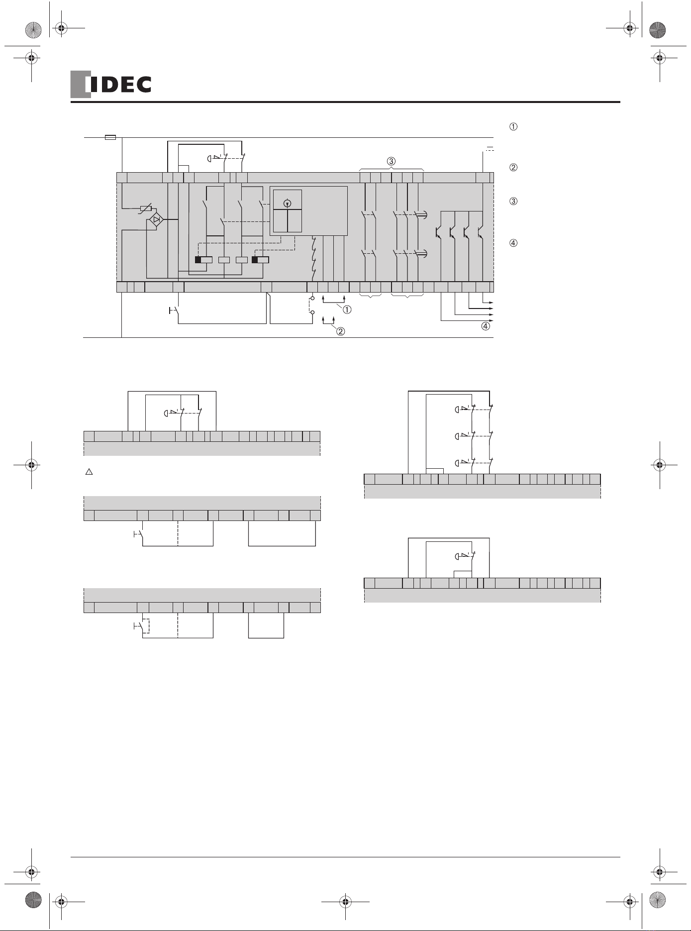
La tension d'alimentation est appliquée aux bornes A1/A2 selon la valeur
sur la plaque signalétique. Les unités de commande sont raccordées de
la façon suivante:
L'utilisation d'une voie d'entrée :
Les unités de commande doivent être connectées aux bornes S11-S12.
Les bornes S21-S22 et B1-S12 doivent être shuntées.
L'utilisation de deux voies d'entrée :
Les unités de commande doivent être connectées aux bornes S11-S12 et
S21-S22. Les bornes B1-S11doivent être shuntées.
Pour un raccordement à deux voies, les deux circuits d'entrée sont
alimentés de polarités différentes, ce qui permet la détection des courts-
circuits entre le + et le -. Si la polarité différente n'est pas souhaitée, les
unités de commande doivent être connectées aux bornes S11-S12 et
S11-B1. Les bornes S21-S22 doivent être shuntées. En sélectionnant ce
mode opératoire, une détection des courts-circuits entre le + et le - n'est
pas possible (des écrasements de câble ne sont pas reconnus).
Le bouton de démarrage et les contacts à ouverture, des relais ou des
contacteurs connectés en aval, doivent être insérés dans la boucle de
retour entre les bornes S33 et Y2. La mise en marche de l'appareil n'est
possible que si les relais connectés en aval ayant des fonctions relatives
à la sécurité sont devenus inactifs après avoir reçu l'ordre d'arrêt. La
boucle de retour doit être fermée pour chaque nouvelle mise en marche.
En cas de besoin, la borne Y1 peut être utilisée comme borne de support
pour l'intégration du bouton de démarrage.
La fonction du bouton de démarrage du module HR1S-ATE est définie par le
shuntage de bornes. Lorsque les bornes Y3-Y5 sont reliées entre elles, le
bouton de démarrage est intégré dans la surveillance et les sorties de sécurité
sont activées sur le front descendant de l'impulsion du signal de sortie (lors du
relâchage du bouton de démarrage). Lorsque les bornes Y3-Y4 sont reliées
entre elles, les sorties de sécurité sont activées immédiatement après action
sur le bouton de démarrage à condition que les circuits d'entrée soient fermés.
Le shuntage entre les bornes Y3-Y5 ou Y3-Y4 doit être connecté
directement à l'appareil et le plus court possible.
N'utiliser qu'un seul des deux shunts (Y3-Y5 ou Y3-Y4). Aucune autre
conducteur ne doit être raccordé à ces bornes.
Le module HR1S-ATE est equipé d'un fusible électronique intégré. Le
fusible protège le module contre la destruction par courts-circuits externes
(par exemple court-circuit entre le + et le - des circuits d'entrée). Après
élimination du défaut, le module est prêt à être remis en service après
quelques secondes.
DANGER
TENSION DANGEREUSE
Le montage, la mise en service, les modifications et le rééquipement
ne doivent être effectués que par un électrotechnicien ! Débranchez
l’appareil / le système avant de commencer les travaux !
Dans le cas d’une défaillance de l’installation ou du système, les
appareils du circuit de commande sans isolation électrique peuvent
être sous tension réseau !
Lors de l'installation des appareils, respectez les réglementations de
sécurité pour usage électrique et de la caisse de prévoyance contre
les accidents.
L’ouverture du boîtier ou toute autre manipulation entraîne l’expiration
de la garantie.
Le non-respect de cette directive entraînera la mort, des
blessures graves ou des dommages matériels.
ATTENTION
UTILISATION INAPPROPRIÉE
En cas d'usage non approprié ou d'utilisation non conforme, l'appareil
ne peut plus être utilisé et nous refusons tout recours à la garantie.
Des actions non autorisées peuvent être:
forte charge mécanique de l'appareil, qui survient par ex. lorsqu'il
tombe, ainsi que tensions, courants, températures et humidité en
dehors des limites définies dans les spécifications.
Lors de la première mise en service de la machine/de l'installation,
veuillez contrôler toujours toutes les fonctions de sécurité
conformément aux prescriptions en vigueur et respecter les cycles de
contrôle prescrits pour les dispositifs de sécurité.
Le non-respect de cette directive peut entraîner des lésions
corporelles et/ou des dommages matériels.
ATTENTION
DANGER Á L´INSTALLATION
Respectez le mesures de sécurité suivantes avant
l’installation / le montage ou le démontage :
1. Débranchez l’appareil / le système avant de commencer les travaux !
2. Protégez la machine / le système contre les redémarrages intempestifs !
3. Assurez-vous que la machine est hors tension !
4. Reliez les phases à la terre et court-circuitezles !
5. Couvrez et isolez les pièces voisines sous tension !
6. Le montage des appareils doit être effectué dans une armoire
électrique avec une classe de protection min. IP 54.
Le non-respect de cette directive peut entraîner des lésions
corporelles et/ou des dommages matériels.
ATTENTION
PROTECTION PARTIELLE CONTRE LES CONTACTS ACCIDENTELS
• Classe de protection selon EN/IEC 60529.
• Boîtier / bornes : IP 40 / IP 20.
• Protection des doigts selon EN 50274.
Le non-respect de cette directive peut entraîner des lésions
corporelles et/ou des dommages matériels.
FRANÇAIS
!
!
!
!
HR1S-ATE SAFETY RELAY MODULE OPERATING INSTRUCTIONS
- DC = 98.42 %
- DC = 99 %
Le module HR1S-ATE sert à interrompre en toute sécurité un ou plusieurs
circuits et est conçu pour être intégré aux circuits d'arrêt d'urgence ou de
sécurité selon EN/IEC 60204-1. Il satisfait aux exigences des normes
européennes EN ISO/ISO 13850 pour les arrêts d'urgence et EN/IEC
60204-1 pour les circuits de sécurité. Ces normes concernent en
particulier les cas, où une seule commande d'arrêt d'urgence doit
couper plusieurs circuits (arrêt d'urgence à action indirecte). Le
module répond aux exigences de sécurité pour le contrôle des
interrupteurs de position actionnés par des dispositifs de protection
(EN 1088).
En complément des deux sorties de sécurité à coupure directe de la
catégorie d'arrêt 0 (EN ISO/ISO 13850, EN/IEC 60204-1), le module est
équipé de trois autres sorties à coupure temporisée de la catégorie d'arrêt
1 , qui permettent un ralentissement contrôlé des éléments moteurs afin
d'obtenir l'arrêt définitif (par exemple freinage du moteur par variateur de
vitesse). A la fin de la temporisation présélectionnée, l'alimentation en
énergie est coupée en ouvrant les circuits de sorties temporisés. La
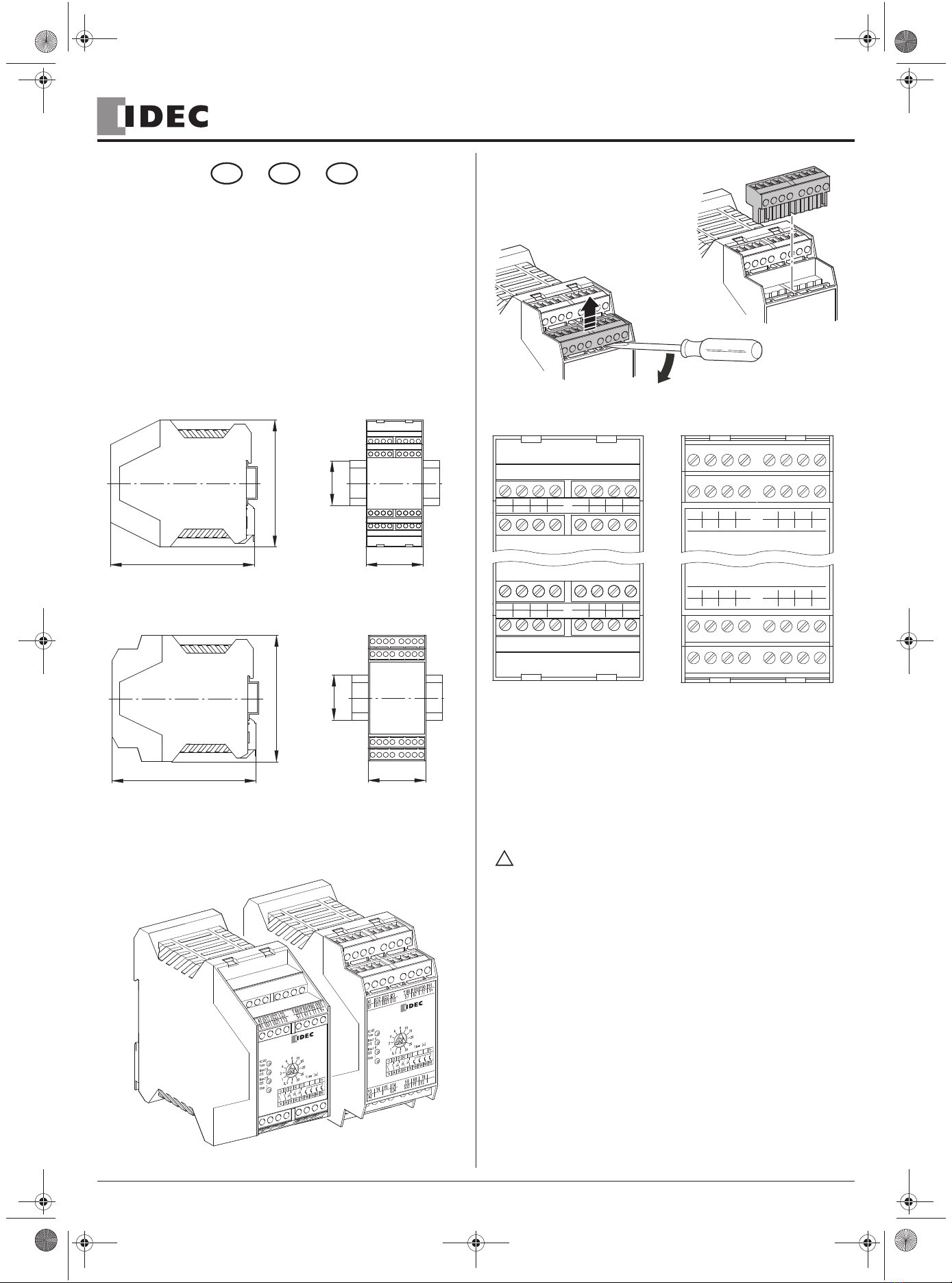
temporisation des trois circuits de sortie entre les bornes 57-58, 67-68 et
77-78 est réglable de 0 à 30 secondes à l'aide d'un sélecteur à 12
positions. Utiliser un tournevis pour tourner le sélecteur sur le couvercle du
boîtier à la valeur souhaitée.
Le module est conçu pour l'utilisation d'entrée à une ou deux voies. Nous
préconisons l'utilisation de deux voies d'entrée augmentant ainsi le niveau
de sécurité. Ce mode opératoire permet d'intégrer toute la connectique
dans la surveillance, tous les premiers défauts sont ainsi détectés.

9 / 18
Usage conforme
L’appareil est destiné au contrôle de postes transmetteurs de signaux, par
ex. les poussoirs Arrêt d’urgence, interrupteurs de position, qui sont
utilisés comme composants de dispositifs de protection sur les machines
dans le but de protéger l’homme, le matériel et la machine.
Note
• L’utilisateur doit effectuer une évaluation du risque conformément à la
norme EN/ISO 14121-1.
• Il convient de réaliser sur cette base une validation de l’ensemble de
l’installation / de la machine selon les normes applicables.
• Le module contient des relais électromécaniques. Par conséquent le
niveau de performance déclaré et sa valeur MTTFddépendent de la
charge et de la fréquence de manœuvre dans le cas d’utilisation. Les
valeurs niveau de performance et MTTFdmentionnées ci-dessus sont
valables pour charge nominale et maximum 6 336 manœuvres par an
ou pour charge faible et maximum 316 800 manœuvres / an.
• Lorsque la charge électrique est connue, le diagramme de durée de vie
électrique (voir pages 16/18) doit être utilisé pour calculer le nombre de
manœuvres maximum. Le niveau de performance indiqué est uniquement
garantit pour le nombre de manœuvres à déterminer. Après atteinte de ce
nombre de manœuvres, l'appareil doit être remplacé. La durée de vie de
l’appareil ne doit cependant pas être dépassée.
• L’utilisation de l’appareil non conforme aux spécifications peut
provoquer des dysfonctionnements ou la destruction de l’appareil.
• L’entrée d’alimentation A1 constitue l’entrée de commande. Ainsi, de
brèves interruptions ou une baisse de la plage de tension de service
UBpeut entraîner la commutation des contacts de sortie.
• Pour la duplication des contacts de sortie, il est possible d’utiliser des
blocs d’extension ou des contacteurs-disjoncteurs externes avec des
contacts à guidage forcé.
• Avant d’activer le poussoir de reset, la chaîne de l’arrêt d’urgence doit
être fermée.
• Lors de la connexion de commutateurs magnétiques avec les contacts
reed ou de détecteurs avec les sorties de semiconducteurs, faire attention
au courant de pointe à l'entrée (voir Caractéristiques techniques).
• Respecter le schéma des installation notes.
Note
Observez également les informations de votre caisse de prévoyance
contre les accidents !
Note
Safety Relay for monitoring EMERGENCY STOP circuits
•
Safety Relay to EN/IEC 60204-1 and EN ISO/ISO 13850 E-stop monitoring.
• For stop category 0 acc. EN/IEC 60204-1:
- PL e / Category 4
- MTTFd= 134.8 Years
- PFHd= 6.81 x 10 -9 1/h
- SILCL 3
• For stop category 1 acc. EN/IEC 60204-1
- PL d / Category 3
- MTTFd= 54.5 Years
- PFHd= 1.96 x 10 -8 1/h
- SILCL 2
ATTENTION
RISQUES RÉSIDUELS (EN ISO/ISO 12100-1)
Le schéma de raccordement proposé ci-dessous a été vérifié et testé
avec le plus grand soin dans des conditions de mise en service. Des
risques subsistent si:
a) le schéma de câblage ci-dessous est modifié par changement
des connexions ou l’adjoncition de composants lorsque ceux-ci
ne sont pas ou insuffisament integré dans le circuit de sécurite.
b) l’utilisateur ne respecte pas les exigences des normes de sécurité
pour le service, le réglage et la maintenance de la machine. Il est
important de respecter strictement les échéances de contrôle et
de maintenance.
Le non-respect de cette directive peut entraîner des lésions
corporelles et/ou des dommages matériels.
!
!
!
!
DANGER
HAZARDOUS VOLTAGE
Only trained professional electricians may install, startup, modify, and
retrofit this equipment!
Disconnect the device / system from all power sources prior to starting
any work!
If installation or system errors occur, line voltage may be present at
the control circuit in devices without DC isolation!
Observe all electrical safety regulations issued by the appropriate
technical authorities or the trade association. The safety function can
be lost if the device is not used for the intended purpose.
Opening the housing or any other manipulation will void the warranty.
Failure to follow this instruction will result in death or serious injury.
CAUTION
UNINTENDEND USE
If the device has been subjected to improper or incorrect use it must
no longer be used, and the guarantee loses its validity.
Impermissible conditions include:
strong mechanical stress, for example through a fall, or voltages,
currents, temperatures or humidity outside of the specifications.
Before starting up your machine/plant for the first time, please be sure
to check all the safety functions according to valid regulations, and
observe the specified test cycles for safety equipment.
Failure to follow this instruction can result in injury or equipment
damage.
CAUTION
RISKS ON INSTALLATION
Perform the following precautionary steps prior to installation,
assembly, or disassembly:
1. Disconnect supply voltage to the equipment / system prior to
starting any work!
2. Lockout/tag the equipment / system to prevent accidental activation!
3. Confirm that no voltage is present!
4. Ground the phases and short to ground!
5. Protect against adjacent live components using guards and barriers!
6. The devices must be installed in a cabinet with a protection class
of at least IP 54.
Failure to follow this instruction can result in injury or equipment
damage.
CAUTION
LIMITED CONTACT PROTECTION
• Protection type according to EN/IEC 60529.
• Housing/terminals: IP 40 / IP 20.
• Finger-proof acc. to EN 50274.
Failure to follow this instruction can result in injury or equipment
damage.
ENGLISH
!
!
!
!
HR1S-ATE SAFETY RELAY MODULE OPERATING INSTRUCTIONS
- DC = 99 %
- DC = 98.42 %
Le module ne contient pas de composants soumis à maintenance par
l'utilisateur. Pour l'autorisation d'un circuit de sécurité selon
EN/IEC60204-1 / E N I SO /I S O 13850 il impératif d'utiliser seulement
les circuits de sortie libres de potentiel entre les bornes 13-14, 23-24 ou
57-58, 67-68 et77-78 en fonction de la catégorie d'arrêt correspondant.
• Le niveau de performance et la catégorie de sécurité selon la norme EN
ISO/ISO 13849-1 dépendent du câblage extérieur, du cas d’application,
du choix de l’émetteur d’ordres et de l’agencement sur la machine sur
place.

10 / 18
• Manual or automatic start
• 3 Enabling paths, 1 signalling path
• Feedback loop to monitoring external contactors
Application
Safety systems are comprised of many components. No one safety
component will insure the safety of the system. The design of the
complete safety system should be considered before you begin. It is very
important to follow applicable safety standards when installing and wiring
these components.
Disclaimer
Electrical equipment should be installed, operated, serviced, and
maintained only by qualified personnel.
Function
The supply voltage has to be connected to terminals A1/A2 according to
the voltage printed on the product label. The control units must be
connected as follows:
Use of one input channel:
Connect the control units (emergency stop) contacts to terminals S11-
S12. Terminals S21-S22 and B1-S12 must be jumpered.
Use of two input channels:
Connect the control units (emergency stop) contacts to terminals S11-S12
and S21-S22 . Terminals B1-S11 must be jumpered.
Using the two channel connection, the two input circuits are supplied with
different polarities, which enables the detection of short circuits between
the + and the -. If the different polarity is not desired, connect the control
units to terminals S11-S12 and S11-B1, and terminals S21-S22 must be
jumpered. In this operation mode a detection of short circuits between the
+ and the - is not possible (pinched cables will not be detected).
The start button as well as the N/C contacts of the external relays or
contactors switched by the safety function outputs have to be integrated
in the feedback loop between the terminals S33 and Y2. The device can
only be switched on if the relevant relays are de-energized after a
preceding stop command. The feedback loop must be closed for every
new start command. If necessary, terminal Y1 can be used as additional
terminal for ease of wiring. Terminal Y1 is not connected internally.
The function of the start button is determined by the location of a jumper. If
terminals Y3-Y5 are interconnected, the start button is integrated in the
monitoring. In this configuration, the outputs of the module are activated at
the trailing edge of the start signal (at the release of the start button). If
terminals Y3-Y4 are jumpered, the outputs are activated immediately after
actuation of the start button provided that the input device circuits are closed.
The configuration jumper between terminals Y3-Y5 or Y3-Y4 must be
short and connected directly to the device.
It is imperative to use only one of the two possible jumpers (i.e., either Y3-
Y5 or Y3-Y4). Do not make any other connections to these terminals or
The HR1S-ATE module is equipped with an internal electronic fuse, which
protects the module against damage by external short circuits (e. g. short
circuits between the + and the - of the input circuits). A few seconds after
elimination of the abnormal condition, the module is operative again.
Proper use
The device is for monitoring sensors (e.g. emergency stop buttons,
position switches) that are used as part of the safety equipment of
machines for the purpose of protecting people, material and machinery.
Note
• The entire system/machine must undergo validation in accordance
with the applicable standards on the basis of this.
• The module contains electro-mechanical relays. Therefore his
indicated performance level and his MTTFdvalue depend on the load
and on the operating cycles in the application. The above mentioned
performance level and MTTFdvalues are suitable for nominal load and
maximum 6.336 switching cycles per year or for low load and
maximum 316.800 switching cycles per year.
• If the current load is known, use the diagram for the electrical service
life (see page 16/18) to calculate the maximum number of switching
cycles. The specified performance level can only be assured for
the number of switching cycles calculated using this method.
The device must be replaced on reaching this maximum figure.
Thereby the lifetime of the device must not be exceeded.
• Operating the device not within the specifications may lead to
malfunctions or the destruction of the device.
• The supply input A1 serves as a control input. This may lead to short
disruptions or a lowering below the operating voltage UBin order to
switch to the release path.
• Expansion devices or external contactors with positively driven
contacts can be used to duplicate the enabling current paths.
• The emergency stop chain must be closed before the reset button is
activated.
• If magnetic switches with reed contacts or sensors with semiconductor
outputs are connected the switch ON peak current must be noticed
(see Technical Data).
• Please consult the installation notes.
Note
Please observe instructions from safety authorities.
Note
There are no user serviceable components in the module. Use only the
hard contacts outputs between terminals 13-14 and 23-24 for stop category
0, and between terminals 57-58, 67-68 and 77-78 for stop category 1.
CAUTION
EQUIPMENT DAMAGE
• Install external fuse as shown on the "WIRING DIAGRAM FOR
MODULE HR1S-ATE SAFETY RELAY."
• See also the "TECHNICAL DATA" of this Instruction Sheet for
information on output protection.
Failure to follow this instruction can result in injury or equipment
damage.
!
!
!
!
!
HR1S-ATE SAFETY RELAY MODULE OPERATING INSTRUCTIONS
The HR1S-ATE module provides an interruption of one or several circuits and
is designed to be integrated into emergency stop or safety circuits conforming
to EN/IEC 60204-1. It meets the requirements of European standard EN
ISO/ISO 13850 for emergency stop equipment and EN/IEC 60204-1 for
safety circuits in general. These standards are related in particular to
applications in which a single emergency stop command must open several
circuits (emergencystop by indirect action). The module meets also the
safety requirements for electrical monitoring of limit switches at interlocking
guards (EN 1088).
In addition to the two direct opening safety function outputs of stop
category 0 (EN ISO/ISO 13850, EN/IEC 60204-1), the module is
equipped with three additional delayed opening outputs of stop category
1. These additional outputs allow a controlled slowing-down of the drive
units to obtain the definitive stop (e. g. motor braking by means of a
variable speed drive). At the end of the preselected delay time the power
supply is disconnected by opening the delayed output circuits. The time
delay of the three output circuits between the terminals 57-58, 67-68 and
77-78 can be adjusted from 0 to 30 seconds by means of a 12 position
selector switch located in the front cover. Use a screwdriver to set the
desired time delay.
The module is designed for use with one or two input channels. Due to
the extended possibilities of fault detection we recommend the use of
two input channels. In this operation mode the connection cables are
integrated in the monitoring and all first faults will be detected.
• The performance level and safety category in accordance with EN
ISO/ISO 13849-1 depends on the external wiring, the application case,
the choice of control station and how this is physically arranged on the
machine.
• The user must carry out a risk assessment in accordance with EN
ISO/ISO 14121-1.
No responsibility is assumed by IDEC for any consequences arising out
of the use of this material.
the device may become inoperative.

11 / 18
Überwachungsbaustein für Not-Halt Kreise
•
Überwachungsbaustein nach EN/IEC 60204-1 und EN ISO/ISO 13850 für
Not-Halt - Überwachung
• Für Stop-Kategorie 0 gemäß EN/IEC 60204-1:
- PL e / Kategorie 4
- MTTFd= 134,8 Jahre
- PFHd= 6,81 x 10 -9 1/h
- SILCL 3
• Für Stop-Kategorie 1 gemäß EN/IEC 60204-1:
- PL d / Kategorie 3
- MTTFd= 54,5 Jahre
- PFHd= 1,96 x 10 -8 1/h
- SILCL 2
• Manueller oder automatischer Start
• 3 Freigabestrompfade, 1 Meldestrompfad
• Rückführkreis zur Überwachung externer Schütze
Anwendungsbereich
CAUTION
The following wiring diagram has been tested under actual service
conditions. This module must be used for safety-related functions in
conjunction with the connected safety equipment and devices that
meet applicable standard requirements. A residual risk will remain if:
a) it is necessary to modify this recommended circuit and if the
added/modified components are not properly integrated in the
control circuit.
b) the user does not follow the required standards applicable to the
operation of the machine, or if the adjustments to and
maintenance of the machine are not properly made. It is
essential to strictly necessary to follow the prescribed machine
maintenance schedule.
c) the device connected to the safety outputs do not have
Failure to follow this instruction can result in injury or equipment
damage.
WARNING
• Wire safety relay using wiring diagrams provided.
• Wire to meet applicable standards requirements.
• All devices connected to the safety outputs must have
mechanicallylinked contacts.
• It is imperative that properly sized external fuses be connected as
shown in wiring diagrams provided.
• Strictly follow prescribed maintenance schedule when making
adjustments to and maintenance of machine.
Failure to follow this instruction can result in death, serious
injury, or equipment damage.
WARNING
• If the recommended circuit is modified or if components are added /
modified, verify that they are properly integrated in the control circuit.
• Relays must have mechanically-linked contacts.
• Follow the required standards applicable to the operation of the
machine and verify that any adjustments are done properly in
accordance with the prescribed machine maintenance schedule.
• Wire safety relay using the wiring scheme shown in the following
diagram.
Failure to follow this instruction can result in death, serious
injury, or equipment damage.
GEFAHR
Die Montage, Inbetriebnahme, Änderung und Nachrüstung darf nur
von einer Elektrofachkraft ausgeführt werden!
Schalten Sie das Gerät/ die Anlage vor Beginn der Arbeiten
spannungsfrei!
Bei Installations und Anlagenfehlern kann bei nicht galvanisch
getrennten Geräten auf dem Steuerkreis Netzpotential anliegen!
Beachten Sie für die Installation der Geräte die Sicherheitsvorschriften
der Elektrotechnik und der Berufsgenossenschaft.
Durch Öffnen des Gehäuses oder sonstige Manipulation erlischt
jegliche Gewährleistung.
Die Nichtbeachtung dieser Anweisung wird Tod oder schwere
Körperverletzung zur Folge haben.
!
!
!
DEUTSCH
!
VORSICHT
Bei unsachgemäßen Gebrauch oder nicht bestimmungsgemäßer
Verwendung darf das Gerät nicht mehr verwendet werden und es
erlischt jeglicher Gewährleistungsanspruch.
Nicht zulässige Einwirkungen können sein:
starke mechanische Belastung des Gerätes, wie sie z.B. beim
Herunterfallen auftritt, Spannungen, Ströme, Temperaturen,
Feuchtigkeit außerhalb der Spezifikation.
Bitte überprüfen Sie gemäß der geltenden Vorschriften bei
Erstinbetriebnahme Ihrer Maschine/ Anlage immer alle
Sicherheitsfunktionen und beachten Sie die vorgegebenen Prüfzyklen
für Sicherheitseinrichtungen.
Die Nichtbeachtung dieser Anweisung kann Körperverletzung
oder Materialschäden zur Folge haben.
VORSICHT
Führen Sie vor Beginn der Installation/ Montage oder Demontage
folgende Sicherheitsmaßnahmen durch:
1. Schalten Sie das Gerät/ die Anlage vor Beginn der Arbeiten
spannungsfrei!
2. Sichern Sie die Maschine/ Anlage gegen Wiedereinschalten!
3. Stellen Sie die Spannungsfreiheit fest!
4. Erden Sie die Phasen und schließen Sie diese kurz!
5. Decken und schranken Sie benachbarte, unter Spannung
stehende Teile ab!
6. Der Einbau der Geräte muss in einem Schaltschrank mit einer
Schutzart von mindestens IP 54 erfolgen.
Die Nichtbeachtung dieser Anweisung kann Körperverletzung
oder Materialschäden zur Folge haben.
VORSICHT
• Schutzart nach EN/IEC 60529.
• Gehäuse/Klemmen: IP 40 / IP 20.
• Fingersicher nach EN 50274.
Die Nichtbeachtung dieser Anweisung kann Körperverletzung
oder Materialschäden zur Folge haben.
!
!
!
HR1S-ATE SAFETY RELAY MODULE OPERATING INSTRUCTIONS
- DC = 98,42 %
- DC = 99 %
Das Gerät HR1S-ATE dient dem sicherheitsgerichteten Unterbrechen eines
oder mehrerer Stromkreise(s) und ist zur Anwendung in Not-Halt und
Sicherheitsstromkreisen gemäß EN/IEC 60204-1 bestimmt. Es erfüllt die
Europanormen EN ISO/ISO 13850 für Not-Halt Einrichtungen sowie EN/IEC
60204-1 für Sicherheitsstromkreise allgemein, zu denen im besonderen auch
die Fälle zählen, in denen mit einem Not-Halt Befehl mehrere Stromkreise
abgeschaltet werden sollen (indirekt wirkender Not-Halt). Der Baustein erfüllt
ebenfalls die sicherheitstechnischen Anforderungen der elektrischen
Überwachung von Positionsschaltern an trennenden Schutzeinrichtungen
(EN 1088).
mechanically-linked contacts.
RESIDUALRISK(EN ISO/ISO 12100-1)
FAILURETO PROTECT
IMPROPER CIRCUITAND MAINTENANCE
GEFÄHRLICHESPANNUNG
UNSACHGEMÄSSERGEBRAUCH
GEFAHRBEIINSTALLATION
EINGESCHRÄNKTERBERÜHRUNGSSCHUTZ

12 / 18
Der Baustein stellt neben zwei direkt abschaltenden Sicherheitsausgängen
der Stop-Kategorie 0 (EN ISO/ISO 13850, EN/IEC 60204-1) noch drei weitere,
zeitverzögert abschaltende Ausgänge der Stop-Kategorie 1 zur Verfügung.
Diese ermöglichen ein gesteuertes Stillsetzen der Antriebselemente, um den
Halt zu erreichen (z.B. Motorbremsung mittels Frequenzumrichter). Nach
Ablauf der vorgewählten Verzögerungszeit erfolgt das sichere Unterbrechen
der Energiezufuhr durch Öffnen der zeitverzögerten Ausgangskreise. Die
Verzögerungszeit der beiden Ausgangskreise zwischen den Klemmen 57-
58, 67-68 und 77-78 ist in zwölf Stufen von 0-30 Sekunden einstellbar. Hierzu
wird die Wählscheibe im Gehäusedeckel unter Zuhilfenahme eines
Schraubendrehers auf den gewünschten Verzögerungswert eingestellt.
Das Gerät ist für einkanalige und zweikanalige Eingangsbeschaltung
geeignet. Aufgrund der erweiterten Fehlerdetektionsmöglichkeiten und
des daraus resultierenden höheren Sicherheitsniveaus wird die
zweikanalige Eingangsbeschaltung empfohlen. In dieser Betriebsart
werden ebenfalls die Anschlußleitungen in die Überwachung einbezogen
und alle Erstfehler werden entdeckt.
Funktion
Die Versorgungsspannung wird gemäß markiertem Wert auf dem
Typenschild an die Klemmen A1/A2 angeschlossen. Der Anschluß der
Befehlsgeräte ist wie folgt vorzunehmen:
Einkanalige Eingangsbeschaltung:
Die Befehlsgeräte sind an die Klemmen S11-S12 anzuschließen. Die
Klemmen S21-S22 sowie B1-S12 sind zu brücken.
Zweikanalige Eingangsbeschaltung:
Die Befehlsgeräte sind an die Klemmen S11-S12 und S21-S22
anzuschließen. Die Klemmen B1-S11 sind zu brücken.
Bei zweikanaligem Anschluß werden beide Eingangskreise mit unter-
schiedlicher Polarität versorgt, welches die Detektion von Querschlüssen
ermöglicht. Wird keine unterschiedliche Polarität gewünscht, sind die
Befehlsgeräte an die Klemmen S11-S12 und S11-B1 anzuschließen. Die
Klemmen S21-S22 sind zu brücken. In dieser Betriebsart ist keine Detektion
von Querschlüssen möglich (Kabelquetschungen werden nicht erkannt).
Die Starttaste sowie die Öffnerkontakte der den Ausgangskanälen
nachgeschalteten Relais oder Schütze sind in den Rückführkreis zwischen
den Klemmen S33 und Y2 einzuschleifen. Dadurch gelingt eine
Einschaltung des Gerätes nur dann, wenn die nachgeschalteten Relais,
welche sicherheitsrelevante Funktion haben, nach einem vorausgangenem
Abschaltbefehl abgefallen waren. Der Rückführkreis muß für jede neue
Einschaltung geschlossen sein. Die Klemme Y1 kann bei Bedarf als
Stützklemme zur Einbindung des Starttasters verwendet werden.
Die Funktion der Starttaste wird durch eine Drahtbrücke festgelegt. Werden die
Klemmen Y3-Y5 verbunden, ist der Starttaster in die Überwachung einbezogen
(empfohlene Verwendung). Die Ausgänge des Bausteins werden in dieser
Konfiguration erst mit fallender Flanke des Startsignals (bei Loslassen des
Starttasters) durchgeschaltet. Werden die Klemmen Y3-Y4 gebrückt, schalten
die Ausgänge unmittelbar nach Betätigung des Starttasters durch, sofern die
Eingangskreise zu diesem Zeitpunkt geschlossen sind.
Die Konfigurationsbrücke zwischen den Klemmen Y3-Y5 oder Y3-Y4 darf nur am
Gerät direkt verdrahtet werden und sollte so kurz wie möglich gewählt werden.
Es darf immer nur eine von beiden Brücken vorhanden sein (Y3-Y5 oder
Y3-Y4) und es dürfen keinesfalls andere Verbindungen an diese
Klemmen verdrahtet werden.
Das Gerät HR1S-ATE arbeitet in allen verfügbaren Spannungsversionen
sicherungslos. Eine eingebaute elektronische Sicherung schützt das Gerät
vor Zerstörung durch äußere Kurzschlüsse (z.B. bei Querschlüssen in der
Eingangsbeschaltung). Nach Beseitigung der Fehlerursache ist der
Baustein nach einigen Sekunden wieder betriebsbereit.
Bestimmungsgemäße Verwendung
Das Gerät dient der Überwachung von Signalgebern z.B. Not-Halt-
Tastern, Positionsschaltern, welche als Teil von Schutzeinrichtungen an
Maschinen zum Zweck des Personen-, Material- und Maschinenschutzes
eingesetzt werden.
Hinweis
• Der Performance-Level sowie die Sicherheits-Kategorie nach EN ISO/ISO
13849-1 hängt von der Außenbeschaltung,dem Einsatzfall, der Wahl
der Befehlsgeber und deren örtlicher Anordnung an der Maschine ab.
• Der Anwender muss eine Risikobeurteilung nach EN ISO/ISO 14121-1
durchführen.
• Auf dieser Basis muss eine Validierung der Gesamtanlage / -maschine
nach den einschlägigen Normen durchgeführt werden.
• Das Modul enthält elektromechanische Relais und somit ist sein
angegebener Performance-Level und sein MTTFdWert abhängig von
der Last und der Schalthäufigkeit im Anwendungsfall. Bei Nennlast
und maximal 6.336 Schaltungen pro Jahr oder bei geringer Last und
maximal 316.800 Schaltungen pro Jahr ergeben sich die obigen Werte
für den Performance- Level und den MTTFd.
• Bei bekannter Strombelastung ist das Diagramm für die elektrische
Lebensdauer (siehe Seite 16/18) für die Berechnung der maximalen
Schaltspiele heranzuziehen. Der angegebene Performance-Level ist
nur für diese zu ermittelnden Schaltspiele gewährleistet.
Nach Erreichen dieser Schaltspiele ist das Gerät auszutauschen. Die
Lebensdauer des Gerätes darf dabei nicht überschritten werden.
• Das Betreiben des Gerätes außerhalb der Spezifikation kann zu
Funktionsstörungen oder zur Zerstörung des Gerätes führen.
• Der Eingang A1 ist der Steuereingang, deshalb können kurze
Unterbrechungen oder eine Absenkung unterhalb von UBzum
Schalten der Freigabepfade führen.
• Zur Vervielfältigung der Freigabestrompfade können
Erweiterungsgeräte oder externe Schütze mit zwangsgeführten
Kontakten eingesetzt werden.
• Bevor der Reset-Taster aktiviert wird, muss die Not-Halt-Kette
geschlossen sein.
• Beim Anschluss von Magnetschaltern mit Reedkontakten oder
Sensoren mit Halbleiter-Ausgängen muss der Einschaltspitzenstrom
beachtet werden (siehe Technische Daten).
• Beachten Sie die Installationshinweise.
Hinweis
Bitte beachten Sie auch die Informationen Ihrer Berufsgenossenschaft!
Hinweise
Das Gerät enthält keine vom Anwender zu wartenden Bauteile. Zur
Freigabe eines Sicherheitsstromkreises gemäß EN/IEC 60204-1 / EN ISO/ISO
13850 sind ausschließlich die potentialfreien Ausgangskreise zwischen
den Klemmen 13-14, 23-24 bzw. 57-58, 67-68 und 77-78 entsprechend
der jeweiligen Stop-Kategorie zu verwenden.
!
VORSICHT
RESTRISIKEN (EN ISO/ISO 12100-1)
Der nachstehende Schaltungsvorschlag wurde mit größter Sorgfalt unter
Betriebsbedingungen geprüft und getestet. Er erfüllt mit der
angeschlossenen Peripherie sicherheitsgerichteter Einrichtungen und
Schaltgeräte insgesamt die einschlägigen Normen. Restrisiken
verbleiben wenn:
a) vom vorgeschlagenen Schaltungskonzept abgewichen wird und
dadurch die angeschlossenen sicherheitsrelevanten Geräte oder
Schutzeinrichtungen möglicherweise nicht oder nur unzureichend
in die Sicherheitsschaltung einbezogen werden.
b) vom Betreiber die einschlägigen Sicherheitsvorschriften für
Betrieb, Einstellung und Wartung der Maschine nicht eingehalten
werden. Hier sollte auf strenge Einhaltung der Intervalle zur
Prüfung und Wartung der Maschine geachtet werden.
Die Nichtbeachtung dieser Anweisung kann Körperverletzung
oder Materialschäden zur Folge haben.
!
!
!
HR1S-ATE SAFETY RELAY MODULE OPERATING INSTRUCTIONS

13 / 18
Schéma de raccordement pour le module de surveillance HR1S-ATE
Wiring diagram for module HR1S-ATE Safety Relay
Anschlußschema für Überwachungsbaustein HR1S-ATE
S2
S1
S11S21
A1 13 57 67
A2
S33
Y1 Y2 Y3 Y4 Y5 14 24 6858
S22
B1
S12
23
F1
(max. 4A)
K2 K4K1
K1 K2
K3
L1 (+)
N (–)
K3
K4
K1
K2
Timer 1
Time (s)
Timer 2
ESC
K1
K2
K3
K4
HR1S-ATE
LOGIC
Stop
Cat. 0 Stop
Cat. 1
77
78 Y88 Y89 Y90 Y91
Y+
(A1/A2)
(S12)
(S22)
(Stop1)
Avec surveillance du bouton
de démarrage (Ètat de
livraison, application
conseillèe)
With monitoring of the start
button, switching on the trailing
edge (Delivered condition,
recommended application)
Mit Starttasterüberwachung
(Lieferzustand, empfohlene
Verwendung)
Sans surveillance du bouton
de démarrage
Without monitoring of the start
button, switching on the
leading edge
Ohne Starttasterüberwachung
Les sorties doivent être
protégées par fusibles (voir
caractéristiques techniques
pour le calibre maximal des
fusibles)
Outputs must be fused (see
Technical data for maximum
fuse sizes)
Ausgänge müssen
abgesichert werden (siehe
technische Daten für max.
Sicherung)
vers API
to PLC
zur SPS
S1 = Bouton poussoir d'ARRET D'URGENCE doté de
2 contacts à ouverture (application conseillèe)
EMERGENCY STOP - push button with
two NC contacts (recommended application)
Not-Halt - Taster mit zwei Öffnerkontakten
(empfohlene Verwendung)
S2 = Bouton marche
Start Button
Starttaste
ESC = Conditions externes de démarrage
External start conditions
Externe Startbedingungen
Y1(S33) - Y2: Boucle de retour
Feedback loop
Rückführkreis
S3
S11S21
A1 13 77
S22
B1
S12
23 57 67
S2
S1
HR1S-ATE
Raccordement de plusieurs boutons d'ARRET D'URGENCE
Connection of several EMERGENCY STOP - buttons
Anschluß mehrerer Not-Halt - Taster
S11S21
A1 13 77
S22
B1
S12
23 57 67
S1
HR1S-ATE
Bouton d'ARRET D'URGENCE doté d'un contact à ouverture
(Tous les défauts ne sont pas détectés:
un court-circuit sur le bouton-pussoir d'ARRET D'URGENCE n'est pas
détecté)
EMERGENCY STOP - push button with one NC contact
(Not all faults are detected:
a short-circuit on the EMERGENCY STOP - button is not detected)
Not-Halt - Taster mit einem Öffnerkontakt
(Es werden nicht alle Fehler erkannt:
Eine Brücke über dem Not-Halt - Taster wird nicht erfaßt)
A2
S33
Y1 Y2 Y3 Y4 Y5
HR1S-ATE
S2
Sans surveillance du bouton de démarrage
Without monitoring of the start button, switching on the leading edge
Dotted line around S2 indicates wiring for automatic start
Ohne Starttasterüberwachung
S2
A2
S33
Y1 Y2 Y3 Y4 Y5
HR1S-ATE
Avec surveillance du bouton de démarrage
(Ètat de livraison, application conseillèe)
With monitoring of the start button, switching on the trailing edge
(Delivered condition, recommended application)
Mit Starttasterüberwachung
(Lieferzustand, empfohlene Verwendung)
S11S21A1 7731S22B1 S12 23 57 67
S1
HR1S-ATE
Bouton poussoir d'ARRET D'URGENCE doté de 2 contacts à ouverture
( Pas de detection d'un court-circuit entre les bornes B1-S12)
EMERGENCY STOP - push button with two NC contacts
( A short-circuit between the terminals B1-S12 is not detected)
NOT AUS - Taster mit zwei Öffnerkontakten
( ohne Querschlußüberwachung)
!
!
!
HR1S-ATE SAFETY RELAY MODULE OPERATING INSTRUCTIONS
+24V
T

14 / 18
Schéma de câblage du module de surveillance HR1S-ATE raccordé au et convertisseur de fréquence
Wiring diagram for module HR1S-ATE Safety Relay connected to Variable Speed Drive
Anschlußschema für Überwachungsbaustein HR1S-ATE in Verbindung mit Frequenzumrichter
Diagnostic du système à l'aide des DEL dans le couvercle du boîtier:
System diagnotics LEDs on the front cover:
Systemdiagnose mittels LED-Anzeige im Gehäusedeckel:
S2
S1
S11S21
A1 13 57 67
A2
S33
Y1 Y2 Y3 Y4 Y5 14 24 786858
S22
B1
S12
23 77
F3
KM1
KM2
KM2KM1
Q1
KM2
U
W
KM1
W
V
M1
3
F1
+ 24 V
L3L2
U/T1 V/T2
W/T3
L1
R1
T1
FW RV
HR1S-ATE
0…30 s
F2
PLC
(1)
(2)
(A1/A2)
Y88 Y89 Y90 Y91
Y+
(S12)
(S22)
(Stop1)
(1) = Avec surveillance du bouton de démarrage
(Ètat de livraison, application conseillèe)
With monitoring of the start button, switching on the trailing edge
(Delivered condition, recommended application)
Mit Starttasterüberwachung
(Lieferzustand, empfohlene Verwendung)
(2) = Voir caractéristiques techniques pour le calibre
maximal des fusibles.
See Technical Data for maximum fuse sizes.
Siehe technische Daten für max. Sicherung.
Convertisseur de fréquence
Frequency converter
Frequenzumrichter
vers API
to PLC
zur SPS
1 A1/A2 - Fuse
2 Input A - S12
3 Input B - S22
4 Stop 1
Disposition des DEL dans le couvercle du boîtier
Arrangement of LEDs in the cover
Anordnung der Leuchtdioden im Gehäusedeckel
DEL 1: (A1/A2 - Fuse)
Présence tension aux bornes A1/A2.
DEL 2: (Input A - S12)
La DEL 2 indique l'état du premier circuit
d'entrée entre les bornes S11-S12. Lorsque le
potentiel positif est présent sur la borne S12, la
DEL 2 s'allume.
DEL 3: (Input B - S22)
La DEL 3 indique l'état du deuxième circuit
d'entrée entre les bornes S21-S22. Lorsque le
potentiel négatif est présent sur la borne S22, la
DEL 3 s'allume.
DEL 4: (Stop 1)
La DEL 4 indique l'état des trois circuits de sortie
temporisés. Lorsque les sorties 57-58, 67-68 et
77-78 sont fermées la DEL 4 s'allume.
LED 1: (A1/A2 - Fuse)
Supply voltage is present on terminals A1/A2.
LED 2: (Input A - S12)
LED 2 indicates the status of the first input circuit
between terminals S11-S12. If the positive
potential is present on terminal S12, LED 2 is lit.
LED 3: (Input B - S22)
LED 3 indicates the status of second input circuit
between terminals S21-S22. If the negative
potential is present on terminal S22, LED 3 is lit.
LED 4: (Stop 1)
LED 4 indicates the status of the three delayed
output circuits. If the outputs 57-58, 67-68 and
77-78 are closed, LED 4 is lit.
LED 1: (A1/A2 - Fuse)
Versorgungsspannung an den Klemmen A1/A2
ist vorhanden.
LED 2: (Input A - S12)
LED 2 signalisiert den Zustand des ersten
Eingangskreises zwischen den Klemmen S11-
S12. Bei vorhandenem Pluspotential an
Klemme S12 leuchtet LED 2.
LED 3: (Input B - S22)
LED 3 signalisiert den Zustand des zweiten
Eingangskreises zwischen den Klemmen S21-
S22. Bei vorhandenem Minuspotential an
Klemme S22 leuchtet LED 3.
LED 4: (Stop 1)
LED 4 signalisiert den Zustand der drei zeit-
verzögert öffnenden Ausgangskreise. Sind die
Ausgänge 57-58, 67-68 und 77-78 geschlossen,
leuchtet LED 4.
HR1S-ATE SAFETY RELAY MODULE OPERATING INSTRUCTIONS
S2
S1
S11S21
A1 13 57 67
A2
S33
Y1 Y2 Y3 Y4 Y5 14 24 786858
S22
B1
S12
23 77
F3
KM1
KM2
KM2KM1
Q1
KM2
U
W
KM1
W
V
M1
3
F1
+ 24 V
L3L2
U/T1 V/T2
W/T3
L1
R1
T1
FW RV
HR1S-ATE
0…30 s
F2
PLC
(1)
(2)
(A1/A2)
Y88 Y89 Y90 Y91
Y+
(S12)
(S22)
(Stop1)
(1) = 起動ボタンのモニタリングあり、立ち下がり時に起動
(工場出荷状態・推奨)
(2) = 最大ヒューズサイズについては技術仕様を参照
周波数変換器
PLC へ
+24V
PE
PE
PE
+24V

15 / 18
Diagrammes fonctionnels du HR1S-ATE / Functional diagrams HR1S-ATE / Funktionsdiagramme HR1S-ATE
Avec surveillance du bouton de
démarrage, Y3-Y5 shunté
(État de livraison, application
conseillèe)
With monitoring of the start button,
with Y3-Y5 jumpered
(Delivered condition, recommended
application)
Mit Starttasterüberwachung,
Y3 - Y5 gebrückt
(Lieferzustand, empfohlene
Verwendung)
Sans surveillance du bouton de
démarrage, Y3-Y4 shunté
Without monitoring of the start button,
with Y3-Y4 jumpered
Ohne Starttasterüberwachung,
Y3 - Y4 gebrückt
Légende
Legend
Legende
Activé
On
Ein
Désactivé
Off
Aus
Tension d'alimentation
Supply On énnoitcaecnegru'dtêrrAniEgnunnapS Emergency stop button
operated
Not-Halt betätigt
Arrêt d'urgence non
áctionné
Emergency stop
button not operated
Not-Halt unbetätigt
Départ
Start
Start
Arrêt d'urgence (O1)
Emergency Stop (NC1)
Not-Halt (Ö1)
Arrêt d'urgence (O2)
Emergency Stop (NC2)
Not-Halt (Ö2)
Bouton marche
Start Button
Starttaste
tmax.= 75 ms
Bouton marche
Start Button
Starttaste
Tv = 0 ... 30s
réglable / adjustable / einstellbar
Bouton marche
Start Button
Starttaste
Sortie 77-78 (F)
Output 77-78 (NO)
Ausgang 77-78 (S)
Sortie 23-24 (F)
Output 23-24 (NO)
Ausgang 23-24 (S)
Sortie statique Y88 (A1/A2)
Transistor output Y88 (A1/A2)
Transistorausgang Y88 (A1/A2)
Sortie 67-68 (F)
Output 67-68 (NO)
Ausgang 67-68 (S)
Sortie 57-58 (F)
Output 57-58 (NO)
Ausgang 57-58 (S)
Sortie 13-14 (F)
Output 13-14 (NO)
Ausgang 13-14 (S)
Conditions externes de démarrage
External Start Conditions
Externe Startbedingungen
Sortie statique Y90 (S22)
Transistor output Y90 (S22)
Transistorausgang Y90 (S22)
Sortie statique Y91 (Stop1)
Transistor output Y91 (Stop1)
Transistorausgang Y91 (Stop1)
Sortie statique Y89 (S12)
Transistor output Y89 (S12)
Transistorausgang Y89 (S12)
Bouton de démarrage
(Y3 - Y4 et S33 - Y1 shuntés)
Without START-button
(Jumper over Y3 - Y4 and S33 - Y1)
Ohne Starttaste
(Y3 - Y4 und S33 - Y1gebrückt)
Avec bouton marche
With START-button
Mit Starttaster
Sans bouton de démarrage
Without START-button
Ohne Starttaster
Sorties
Outputs
Ausgänge
Sortie statique Y90 (S22)
Transistor output Y90 (S22)
Transistorausgang Y90 (S22)
Sortie statique Y89 (S12)
Transistor output Y89 (S12)
Transistorausgang Y89 (S12)
Arrêt d'urgence (O2 ou O1)
Emergency Stop (NC2 resp. NC1)
Not-Halt (Ö2 bzw. Ö1)
Arrêt d'urgence (O1 ou O2)
Emergency Stop (NC1 resp. NC2)
Not-Halt (Ö1 bzw. Ö2)
HR1S-ATE SAFETY RELAY MODULE OPERATING INSTRUCTIONS

16 / 18
Electrical life of the output contacts
1
10
100
10 10 10 10
7654
DC 1: 24 V
DC 13: 24 V
(< 0,1 Hz)
AC 15:
230 V
AC 1:
230 V
Version 24V
Courant de commutation x 0,1 A
Nominal Operating Current x 0.1 A
Schaltstrom x 0,1 A
Cycles de manoeuvre
Operation Cycles
Schaltspiele
CARACTERISTIQUES TECHNIQUES
- Données sur les bornes et les connexions
HR1S-ATE5110
Connection un fil
Sans embout:
mm5,2-41,0edigir 2
mm5,2-41,0elbixelf 2
Longueur de dénudage 7 mm
Flexible avec embout
(sans colleret plastique): 0,25-2,5 mm2
(avec colleret plastique): 0,25-1,5 mm2
Couple de rotation min. 0,5 Nm
Connection deux fils
Sans embout:
mm57,0-41,0edigir 2
mm57,0-41,0elbixelf 2
Longueur de dénudage 7 mm
Flexible avec embout
(sans colleret plastique): 0,25-1 mm2
Flexible avec embout TWIN
(avec colleret plastique): 0,5-1,5 mm2
Couple de rotation min. 0,5 Nm
HR1S-ATE5110P
Connection un fil
Sans embout:
mm5,2-2,0edigir 2
mm5,2-2,0elbixelf 2
Longueur de dénudage 7 mm
Flexible avec embout
(sans colleret plastique): 0,25-2,5 mm2
(avec colleret plastique): 0,25-1,5 mm2
Couple de rotation min. 0,5 Nm
TECHNICAL DATA
- Terminals and connection
HR1S-ATE5110
Single wire connection
Without cable end:
solid 0.14-2.5 mm2
stranded 0.14-2.5 mm2
AWG 26-14
Stripping length 7 mm (0.28 in.)
Flexible with cable end
(without plastic sleeve)
: 0.25-2.5 mm2(24-14 AWG1))
(with plastic sleeve):
0.25-1.5 mm2(24-16 AWG1))
Tightening torque, min. 0.5 Nm (4.4 lb-in)
Multiple-wire connection (2 wires max.)
Without cable end:
solid 0.14-0.75 mm2(26-20 AWG1))
stranded 0.14-0.75 mm2(26-20 AWG1))
Stripping length 7 mm (0.28 in.)
Flexible with cable end
(without plastic sleeve)
: 0.25-1 mm2(24-18 AWG1))
Flexible with TWIN-cable end
(with plastic sleeve):
0.5-1.5 mm2(22-14 AWG1))
Tightening torque, min. 0.5 Nm (4.4 lb-in)
HR1S-ATE5110P
Single wire connection
Without cable end:
solid 0.2-2.5 mm2
stranded 0.2-2.5 mm2
Stripping length 7 mm (0.28 in.)
Flexible with cable end
(without plastic sleeve)
: 0.25-2.5 mm2(22-14 AWG1))
(with plastic sleeve):
0.25-1.5 mm2(22-16 AWG1))
Tightening torque, min. 0.5 Nm (4.4 lb-in)
TECHNISCHE DATEN
- Klemmen- und Anschlussdaten
HR1S-ATE5110
Einzelleiteranschluß
Ohne Aderendhülse:
mm5,2-41,0rrats 2
mm5,2-41,0lebixelf 2
mm7egnälreilosibA
Flexibel mit Aderendhülse
(ohne Kunststoffhülse): 0,25-2,5 mm2
(mit Kunststoffhülse): 0,25-1,5 mm2
Anzugsdrehmoment min. 0,5 Nm
Mehrleiteranschluß (2 Leiter max.)
Ohne Aderendhülse:
mm57,0-41,0rrats 2
mm57,0-41,0lebixelf 2
mm7egnälreilosibA
Flexibel mit Aderendhülse
(ohne Kunststoffhülse): 0,25-1 mm2
Flexibel mit TWIN-Aderendhülse
(mit Kunststoffhülse): 0,5-1,5 mm2
Anzugsdrehmoment min. 0,5 Nm
HR1S-ATE5110P
Einzelleiteranschluß
Ohne Aderendhülse:
mm5,2-2,0rrats 2
mm5,2-2,0lebixelf 2
mm7egnälreilosibA
Flexibel mit Aderendhülse
(ohne Kunststoffhülse): 0,25-2,5 mm2
(mit Kunststoffhülse): 0,25-1,5 mm2
Anzugsdrehmoment min. 0,5 Nm
HR1S-ATE SAFETY RELAY MODULE OPERATING INSTRUCTIONS
Durée de vie électrique des contacts de sortie selon EN / IEC 60947-5-1 / Annexe C.3
Electrical life of the output contacts determined by EN / IEC 60947-5-1 / Annex C.3
Elektrische Lebensdauer der Ausgangskontakte gemäß EN / IEC 60947-5-1 / Anhang C.3
AWG 24-12

17 / 18
Connection deux fils
Sans embout:
mm1-2,0edigir 2
mm5,1-2,0elbixelf 2
Longueur de dénudage 7 mm
Flexible avec embout
(sans colleret plastique): 0,25-1 mm2
Flexible avec embout TWIN
(avec colleret plastique): 0,5-1,5 mm2
Couple de rotation min. 0,5 Nm
- Fixation du boîtier:
Encliquetage sur profilé chapeau 35 mm
selon EN/IEC 60715
- Degré de protection selon EN/IEC 60529:
Bornes: IP20
Boîtier: IP40
- Poids:
Version 24V 0,28 kg
- Position de montage: indifférente
- Température de fonctionnement:
-10°C / +55°C
- Catégorie de surtension III (4 kV)
Degré de pollution 2
Tension assignée d’isolement 300 V
selon EN/IEC 60664-1
- Tension d’alimentation UE selon IEC 60038:
24V - 50/60 Hz (+10% / -20%)
24V (+20% / -20%)
(voir plaque signalétique)
Protection max.: 4 A gG
- Puissance consommée:
24 V 8 VA
24 V 4 W
- Sorties de sécurité (libre de potentiel):
13 - 14, 23 - 24 Temps de réponse:
< 20 ms
Catégorie d'arrêt 0,
EN/IEC
60204-1,
EN ISO/ISO 13850
Cat. 4 (EN 954-1)
57 - 58, 67 - 68, 77-78
Catégorie d'arrêt 1,
EN/IEC
60204-1,
EN ISO/ISO 13850
Cat. 3 (EN 954-1)
- Sortie statique, fonction fermeture
(sans contact):
Y+ - Y88, Y+ - Y89, Y+ - Y90, Y+ - Y91
(Typiquement: 24 V / 20 mA)
- Capacité de coupure maxi des sorties:
AC 15 - C300 Ue=230V /Ie = 0,75 A
DC 13 Ue=24 V /Ie = 1 A
Protection max.: 4 A gG
- Durée de vie mécanique (Commutations):
10 x 106
- Limite des courants cumulés (charge
simultanée des plusieurs circuits de sortie):
ΣIth 8 A
(max.: 4 A / Sortie)
- Temps de synchronisation S1-S2
(utilisation sans bouton de démarrage):
env. 75 ms
- Précision du temps: -15% / +15% + 50 ms
Multiple-wire connection (2 wires max.)
Without cable end:
solid 0.2-1 mm2(24-18 AWG1))
stranded 0.2-1.5 mm2(24-16 AWG1))
Stripping length 7 mm (0.28 in.)
Flexible with cable end
(without plastic sleeve): 0.25-1 mm2(22-18 AWG1)
)
Flexible with TWIN-cable end
(with plastic sleeve): 0.5-1.5 mm2(20-16 AWG1))
Tightening torque, min. 0.5 Nm (4.4 lb-in)
1) AWG indication according to
EN/IEC 60947-1 / table 1
- Mounting:
Mounting on 35 mm DIN rail
according to EN/IEC 60715
- Degree of protection per EN/IEC 60529:
Terminals: IP20 (Finger-proof)
Enclosure: IP40
- Weight:
Version 24V 0.28 kg (9.88 oz)
- Mounting position: Any plane
- Ambient operating temperature:
-10°C to +55°C (-14°F to +130°F)
- Overvoltage category III (4 kV)
Pollution degree 2
Rated insulation voltage: 300 V
(EN/IEC 60664-1)
- Supply voltage UE according to IEC 60038:
24V - 50/60 Hz (+10% / -20%)
24V (+20% / -20%)
(Refer to device nameplate for supply voltage)
Max. protection: 4 A fuse gG
- Power consumption:
24 V 8 VA
24 V 4 W
- Safety relay outputs:
13 - 14, 23 - 24 Response time:
< 20 ms
Stop category 0,
EN/IEC
60204-1,
EN ISO
/ISO
13850
Cat. 4 (EN 954-1)
57 - 58, 67 - 68, 77-78
Stop category 1,
EN/IEC
60204-1,
EN ISO
/ISO
13850
Cat. 3 (EN 954-1)
- Transistor outputs, closing function
(contactless):
Y+ - Y88, Y+ - Y89, Y+ - Y90, Y+ - Y91
(Typically: 24 V / 20 mA)
- Maximum switching ratings of outputs:
Max. protection: 4 A fuse gG
- Mechanical service life (Switching operations):
10 x 106
- The sum of simultaneous currents on all of the
outputs is limited to :
Ith 8 A
(max.: 4 A / Output)
- Synchronization time between S1 and S2
(use without start button wired for automatic start)
:
approx. 75 ms
- Time accuracy: -15% / +15% + 50 ms
Mehrleiteranschluß (2 Leiter max.)
Ohne Aderendhülse:
mm1-2,0rrats 2
mm5,1-2,0lebixelf 2
mm7egnälreilosibA
Flexibel mit Aderendhülse
(ohne Kunststoffhülse): 0,25-1 mm2
Flexibel mit TWIN-Aderendhülse
(mit Kunststoffhülse): 0,5-1,5 mm2
Anzugsdrehmoment min. 0,5 Nm
- Gehäusebefestigung:
Schnappbefestigung auf 35 mm
Normschiene nach EN/IEC 60715
- Schutzart gemäß EN/IEC 60529:
Klemmen: IP20
Gehäuse: IP40
- Gewicht:
Version 24V 0,28 kg
- Einbaulage: beliebig
- Umgebungstemperatur im Betrieb:
-10°C / +55°C
- Überspannungskategorie III (4 kV)
Verschmutzungsgrad 2
Bemessungsisolationsspannung 300 V
gemäß EN/IEC 60664-1
- Anschlußspannung UE gemäß IEC 60038:
24V - 50/60 Hz (+10% / -20%)
24V (+20% / -20%)
(Siehe Typenschild)
Absicherung max.: 4 A gG
- Eigenverbrauch:
24 V 8 VA
24 V 4 W
- Sicherheitsausgänge (potentialfrei):
13 - 14, 23 - 24 Ansprechzeit:
< 20 ms
Stop - Kategorie 0,
EN/IEC 60204-1, EN ISO
/ISO
13850
Cat. 4 (EN 954-1)
57 - 58, 67 - 68, 77-78
Stop - Kategorie 1,
EN/IEC 60204-1, EN ISO
/ISO
13850
Cat. 3 (EN 954-1)
- Transistorausgänge Schließerfunktion
(kontaktlos):
Y+ - Y88, Y+ - Y89, Y+ - Y90, Y+ - Y91
(Typisch: 24 V / 20 mA)
- Max. Schaltleistung der Ausgangskanäle:
Absicherung max.: 4 A gG
- Mechanische Lebensdauer (Schaltungen):
10 x 106
- Summenstrombegrenzung bei gleichzeitiger
Belastung mehrerer Ausgangskreise:
Ith 8 A
(max. 4 A / Ausgang)
- Synchronisationszeit S1-S2 bei
Verwendung ohne Starttaster:
ca. 75 ms
- Zeitgenauigkeit: -15% / +15% + 50 ms
<
_
Σ
Σ
<
_
<
_
<
_
<
_
<
_
<
_
<
_
<
_
HR1S-ATE SAFETY RELAY MODULE OPERATING INSTRUCTIONS
AC 15 - C300 Ue=230V /Ie = 0,75 A
DC 13 Ue=24 V /Ie = 1 A
AC 15 - C300 Ue=230V /Ie = 0,75 A
DC 13 Ue=24 V /Ie = 1 A

18 / 18
L'appareil est aussi capable de commuter des
charges faibles (17 V / 10 mA), à condition
que le contact n'ait jamais commuté de forte
charge auparavant, car la couche d'or revêtant le
contact pourrait être altérée.
- Résistivité dans l'alimentation des
actionneurs: max. 33 Ω
Minimum switching ratings of outputs:
The device is capable to switch low voltage loads
(min. 17 V / 10 mA) provided that the contact
has never been used with higher loads.
- Resistance in the voltage supply to the
sensors: max. 33 Ω
Das Gerät ist ebenfalls zum Schalten von Kleinstlasten
(min. 17 V / 10 mA) geeignet. Dies ist jedoch nur
dann möglich, wenn bisher über diesen Kontakt keine
höheren Lasten geschaltet wurden, da hierdurch die
Kontaktvergoldung abgebrannt sein könnte.
- Leitungswiderstand in der Spannungsversorgung
der Befehlsgeber: max. 33 Ω
DÉCLARATION CE DE CONFORMITÉ
POUR LES COMPOSANTS DE SÉCURITÉ
(Traduction française de la Déclaration CE de Conformité
d'origine Référence du document : D1B112, D2B126, D3B026)
Nous: IDEC CORPORATION
7-31, Nishimiyahara 1-chome, Yodogawa-ku, Osaka 532-8550, Japan
Déclarons que le composant de sécurité
MARQUE: IDEC
NOM, TYPE: Modules de sécurité
MODELES: HR1S-ATE
NUMÉRO DE SÉRIE: voir de la Déclaration CE de Conformité d'origine
DATE DE FABRICATION: voir plaque signalétique
est conforme à l'ensemble des recommandations en matière de protection
stipulées dans les consignes suivantes.
Une description de la Déclaration avec les normes européennes
harmonisées est fournie ci-après.:
L'organisme agréé suivant a établi une déclaration positive selon le Chapitre
7, phrase 2, 2004/108/EG:
Sous réserve d’installation, d’entretien et d’utilisation conformes à sa
destination, à la réglementation, aux normes en vigueur, aux instructions du
constructeur et aux règles de l’art.
EC DECLARATION OF CONFORMITY
FOR SAFETY COMPONENTS
(Copy of the original EC declaration of conformity,
Document-no.: D1B112, D2B126, D3B026)
WE: IDEC CORPORATION
7-31, Nishimiyahara 1-chome, Yodogawa-ku, Osaka 532-8550, Japan
hereby declare that the safety component
TRADEMARK: IDEC
PRODUCT, TYPE: Safety relay module
MODELS: HR1S-ATE
SERIAL NUMBER: refer to original EC declaration of conformity
DATE OF MANUFACTURING: refer to device nameplate
all the essential protection requirements that are described in the following
directives are defined, corresponding.
Furthermore, the conformity with the following harmonized European
standards explained:
EG-KONFORMITÄTSERKLÄRUNG
FÜR SICHERHEITSBAUTEILE
(Deutsch übersetzung der original EG-Konformitätserklärung,
Dokument-Nr.: D1B112, D2B126, D3B026)
WIR: IDEC CORPORATION
7-31, Nishimiyahara 1-chome, Yodogawa-ku, Osaka 532-8550, Japan
erklären hiermit, daß das nachstehend aufgeführte Sicherheitsbauteil
MARKE: IDEC
NAME, TYP: Sicherheitsrelais
MODELL: HR1S-ATE
SERIENNNUMMER:siehe original EG-Konformitätserklärung
FERTIGUNGSDATUM: siehe Typenschild
allen wesentlichen Schutzanforderungen, die in den nachfolgenden
bezeichneten Richtlinien festgelegt sind, entspricht.
Weiterhin wird die Konformität mit folgenden harmonisierten Europäischen
Normen erklärt:
DATE DE RÉFÉRENCE: DIRECTIVE:
EN 60204-01:2006
(DIN EN 60204-01:2007-06)
DIRECTIVE 2006/95/CE DU
PARLEMENT EUROPÉEN ET DU
CONSEIL du 12 décembre 2006
concernant le rapprochement des
législations des États membres relatives
au matériel électrique destiné à être
employé dans certaines limites de tension
EN 60947-5-1:2004
(DIN EN 60947-5-1:2005-02)
EN 60947-01:2007
(DIN EN 60947-01:2008-04)
EN 60947-01:2007
(DIN EN 60947-01:2008-04)
DIRECTIVE 2004/108/CE DU
PARLEMENT EUROPÉEN ET DU
CONSEIL du 15 décembre 2004
relative au rapprochement des
législations des États membres
concernant la compatibilité
électromagnétique et abrogeant la
directive 89/336/CEE
EN 61000-6-02:2005
(DIN EN 61000-6-2:2006-03)
EN 61000-6-4:2007
(DIN EN 61000-6-4:2007-09)
EN 60947-5-1:2004
(DIN EN 60947-5-1:2005-02)
EN 62061:2005
(DIN EN 62061:2005-10) DIRECTIVE 2006/42/CE DU
PARLEMENT EUROPÉEN ET DU
CONSEIL du 17 mai 2006
relative aux machines et modifiant la
directive 95/16/CE (refonte)
EN ISO 12100-2:2003
(DIN EN ISO 12100-2:2004-04)
EN ISO 13849-1:2008
(DIN EN ISO 13849-01:2008-12)
EN ISO 13849-2:2008
(DIN EN ISO 13849-2:2008-09)
RÉFÉRENCE DE
L'ORGANISME AGRÉÉ:
REFERENCE DE LA
DECLARATION:
NOM, ADRESSE:
0044 44 205 10 380862 - 0014 TÜV NORDCERTGMBH
Langemarckstr. 20
D-45141 Essen
DATED REFERENCE: DIRECTIVE:
EN 60204-01:2006
(DIN EN 60204-01:2007-06)
DIRECTIVE 2006/95/EC OF THE
EUROPEAN PARLIAMENT AND OF
THE COUNCIL of 12 December 2006
on the harmonisation of the laws of
Member States relating to electrical
equipment designed for use within
certain voltage limits
EN 60947-5-1:2004
(DIN EN 60947-5-1:2005-02)
EN 60947-01:2007
(DIN EN 60947-01:2008-04)
DATIERTE FUNDSTELLE: RICHTLINIENBEZUG:
EN 60204-01:2006
(DIN EN 60204-01:2007-06)
RICHTLINIE 2006/95/EG DES
EUROPÄISCHEN PARLAMENTS UND
DES RATES vom 12. Dezember 2006
zur Angleichung der Rechtsvorschriften der
Mitgliedstaaten betreffend elektrische
Betriebsmittel zur Verwendung innerhalb
bestimmter Spannungsgrenzen
EN 60947-5-1:2004
(DIN EN 60947-5-1:2005-02)
EN 60947-01:2007
(DIN EN 60947-01:2008-04)
HR1S-ATE SAFETY RELAY MODULE OPERATING INSTRUCTIONS
The following notified body has made a positive declaration in accordance
to Chapter 7, Sentence 2, 2004/108/EG:
Itis important that the safetycomponent is subject to correct installation, maintenance
and use conforming to its intended purpose, to the applicable regulations and
standards, to the supplier’s instructions and to accepted rules of the art.
Documentation authority:
Frank Lisker/ IDEC ELEKTROTECHNIK GmbH
Wendenstrasse 331, D-20537 Hamburg, Germany
EN 60947-01:2007
(DIN EN 60947-01:2008-04)
DIRECTIVE 2004/108/EC OF THE
EUROPEAN PARLIAMENT AND OF
THE COUNCIL of 15 December 2004
on the approximation of the laws of the
Member States relating to
electromagnetic compatibility and
repealing Directive 89/336/EEC
EN 61000-6-02:2005
(DIN EN 61000-6-2:2006-03)
EN 61000-6-4:2007
(DIN EN 61000-6-4:2007-09)
EN 60947-5-1:2004
(DIN EN 60947-5-1:2005-02)
EN 62061:2005
(DIN EN 62061:2005-10)
DIRECTIVE 2006/42/EC OF THE
EUROPEAN PARLIAMENT AND OF
THE COUNCIL of 17 May 2006
on machinery, and amending Directive
95/16/EC (recast)
EN ISO 12100-2:2003
(DIN EN ISO 12100-2:2004-04)
EN ISO 13849-1:2008
(DIN EN ISO 13849-01:2008-12)
EN ISO 13849-2:2008
(DIN EN ISO 13849-2:2008-09)
NUMBER OF THE
NOTIFIED BODY:
NUMBER OF
DECLARATION:
NAME, ADDRESS:
0044 44 205 10 380862 - 0014 TÜV NORDCERTGMBH
Langemarckstr. 20
D-45141 Essen
7-31, Nishimiyahara 1-chome, Yodogawa-ku, Osaka 532-8550, Japan
12 - March – 2010
IDEC CORPORATION
Documentation autorité:
Frank Lisker/ IDEC ELEKTROTECHNIK GmbH
Wendenstrasse 331, D-20537 Hamburg, Germany
7-31, Nishimiyahara 1-chome, Yodogawa-ku, Osaka 532-8550, Japan
12 - Mars – 2010
IDEC CORPORATION
Folgende benannte Stelle hat eine positive Erklärung im Sinne des Artikels
7, Satz 2, 2004/108/EG ausgestellt:
Falls es gemäß seiner Bestimmung, den geltenden Vorschriften, Normen
und Herstelleranweisungen entsprechend installiert, verwendet und
gewartet wird.
Dokumentations Bevollmächtigter:
EN 60947-01:2007
(DIN EN 60947-01:2008-04)
RICHTLINIE 2004/108/EG DES
EUROPÄISCHEN PARLAMENTS UND
DES RATES vom 15. Dezember 2004
zur Angleichung der Rechtsvorschriften
der Mitgliedstaaten über die
elektromagnetische Verträglichkeit und
zur Aufhebung der Richtlinie 89/336/
EWG
EN 61000-6-02:2005
(DIN EN 61000-6-2:2006-03)
EN 61000-6-4:2007
(DIN EN 61000-6-4:2007-09)
EN 60947-5-1:2004
(DIN EN 60947-5-1:2005-02)
EN 62061:2005
(DIN EN 62061:2005-10)
RICHTLINIE 2006/42/EG DES
EUROPÄISCHEN PARLAMENTS UND
DES RATES vom 17. Mai 2006
über Maschinen und zur Änderung der
Richtlinie 95/16/EG (Neufassung)
EN ISO 12100-2:2003
(DIN EN ISO 12100-2:2004-04)
EN ISO 13849-1:2008
(DIN EN ISO 13849-01:2008-12)
EN ISO 13849-2:2008
(DIN EN ISO 13849-2:2008-09)
KENNNUMMER DER
BENANNTEN STELLE:
NUMMER DER
ERKLÄRUNG:
NAME, ANSCHRIFT:
0044 44 205 10 380862 - 0014 TÜV NORDCERTGMBH
Langemarckstr. 20
D-45141 Essen
Frank Lisker/ IDEC ELEKTROTECHNIK GmbH
Wendenstrasse 331, D-20537 Hamburg, Germany
7-31, Nishimiyahara 1-chome, Yodogawa-ku, Osaka 532-8550, Japan
12 - März – 2010
IDEC CORPORATION
EN ISO 13850:2008
(DIN EN ISO 13850:2009-08) EN ISO 13850:2008
(DIN EN ISO 13850:2009-08)
EN ISO 13850:2008
(DIN EN ISO 13850:2009-08)
If you need the original EC declaration of conformity, please offer to our sales
person or agency.
Si vous avez besoin de la d
é
claration CE de conformit
é
originale, veuillez vous
adresser
à
notre responsable des ventes ou agence.
Wenn Sie die originale EG-konformit
ä
tserkl
ä
rung brauchen, bieten Sie sich bitte
zu unserer Verkaufsperson oder unserer Agentur.
Other manuals for HR1S-ATE
2
This manual suits for next models
2
Table of contents
Other IDEC Control Unit manuals

IDEC
IDEC HR6S Series User manual

IDEC
IDEC FC5A-F2M2 User manual

IDEC
IDEC MicroSmart pentra FC5A-C10R2 User manual

IDEC
IDEC LONWORKS User manual

IDEC
IDEC MicroSmart Series User manual

IDEC
IDEC HR6S-S User manual

IDEC
IDEC SmartRelay Series User manual

IDEC
IDEC MICROSmart FC4A-SX5ES1E User manual

IDEC
IDEC MicroSmart pentra FC5A-D12K1E User manual

IDEC
IDEC HR6S-DN User manual